

SIMS GRASEBY 3400 Technical & Service Manual
Graseby 3400
Anaesthesia
Syringe Pump
TECHNICAL SERVICE MANUAL
Document Number 00SM-0132 Issue 6.0

SIMS Graseby Ltd.
3400 Service Manual Issue 6 (July 00)
Page i
Published by SIMS Graseby Limited.
All possible care has been taken in the preparation of this publication, but SIMS Graseby
Limited accepts no liability for any inaccuracies that may be found.
SIMS Graseby reserves the right to make changes without notice both to this publication and to
the product which it describes.
© SIMS Graseby Limited 1999
No part of this publication may be reproduced, transmitted, transcribed, or stored in a retrieval
system or translated into any human or computer language in any form by any means without
the prior permission of SIMS Graseby Limited.
SIMS GRASEBY LIMITED,
COLONIAL WAY,
WATFORD,
HERTFORDSHIRE,
UNITED KINGDOM,
WD2 4LG
TEL: (+44) (0)1923 246434
FAX: (+44) (0)1923 231595
REGISTERED IN ENGLAND. COMPANY No. 995550
Copyright and address

SIMS Graseby Ltd.
Page ii
Issue 6.2 (Feb 01)
3400 Service Manual
DROCEREUSSI
.oNeussIegnahcrofnosaeR
segaP
detceffa
etaD
4ot1seussilaitinIllA39ot19
5eussieRllA99ceD
6eussieRllA00yluJ
1.6segapeerhtottnemdnemAdnax,ii
01-5
00tsuguA
2.6segapowtottnemdnemA51-7dnaii10beF

SIMS Graseby Ltd.
3400 Service Manual Issue 6 (July 00)
Page iii
General .................................................................................................... x
Warnings and caution ............................................................................ x
Abbreviations used ............................................................................... xi
CHAPTER 1
INTRODUCTION, FEATURES, CLASSIFICATION AND SPECIFICATION
Introduction ......................................................................................... 1-1
General information ............................................................................ 1-1
Features ............................................................................................... 1-3
Classification .......................................................................................1-3
Specification ........................................................................................1-4
Brief history of Graseby bedside syringe pumps ............................. 1-5
CHAPTER 2
CONFIGURATION & DIAGNOSTIC MODE, AND THRUST ADJUSTMENTS
Configuration mode ............................................................................ 2-1
Calling up the configuration mode ............................................... 2-2
Changing an option .....................................................................2-2
Moving to the next parameter ...................................................... 2-2
Configuration parameters and settings that are available
Syringe brands ............................................................................ 2-2
Display language .........................................................................2-3
Bolus beep ..................................................................................2-3
Preset bolus dose ....................................................................... 2-3
Mass units ...................................................................................2-3
LCD contrast ...............................................................................2-3
Baud rate ..................................................................................... 2-3
Max rate ...................................................................................... 2-3
Diagnostic mode ................................................................................. 2-4
Calling up the Diagnostic mode ................................................... 2-4
Moving to the next parameter ...................................................... 2-4
Diagnostic displays ......................................................................2-4
Exiting from the Diagnostic mode ................................................ 2-5
LIST OF CONTENTS
Contents
Page

SIMS Graseby Ltd.
Page iv
Issue 6 (July 00)
3400 Service Manual
CHAPTER 2 (contd.)
Page
Disassembly and assembly of casing ............................................... 2-5
Taking the casing apart ............................................................... 2-5
Assembly..................................................................................... 2-5
Occlusion measurements ...................................................................2-6
Thrust measurements ................................................................. 2-6
Syringe stiction ............................................................................2-6
Thrust checks ..............................................................................2-7
Thrust adjustments ...................................................................... 2-8
CHAPTER 3
FUNCTIONAL DESCRIPTIONS
Introduction ......................................................................................... 3-1
Drive system ........................................................................................3-1
DC motor and leadscrew .............................................................3-1
Processor ....................................................................................3-1
Toggle mechanism ...................................................................... 3-1
Plunger clamp .............................................................................3-1
Occlusion sensing system .................................................................3-2
Clutch assembly and opto-sensor ............................................... 3-2
Occlusion detection .....................................................................3-2
Electro/mechanical control system .................................................... 3-2
Motor speed ................................................................................ 3-2
Motor rotation .............................................................................. 3-2
Mechanical characteristics .......................................................... 3-2
Sensing (alarm) systems .................................................................... 3-3
Introduction ................................................................................. 3-3
Syringe nearly empty .................................................................. 3-3
End of infusion/occlusion ............................................................. 3-3
AC power failure .......................................................................... 3-3
Battery voltage low ...................................................................... 3-3
Self tests/pump malfunction ........................................................ 3-3
Drive disengaged, or syringe not fitted ........................................ 3-3
Syringe sizing system ................................................................. 3-3
Software ...............................................................................................3-4
Design methods ..........................................................................3-4
Self tests ..................................................................................... 3-4
Contents

SIMS Graseby Ltd.
3400 Service Manual Issue 6 (July 00)
Page v
CHAPTER 4
CIRCUIT DESCRIPTIONS
Page
Introduction ........................................................................................ 4-1
Main board circuit ............................................................................... 4-2
Sub-circuits................................................................................. 4-2
Processor core circuit ........................................................................ 4-2
Description ................................................................................. 4-2
Motor interface circuit description .................................................... 4-3
Introduction................................................................................. 4-3
Motor current control .................................................................. 4-3
Transients; suppression .............................................................. 4-3
Motor speed control .................................................................... 4-3
Power control circuit .......................................................................... 4-4
Logic circuit supply; Vcc.............................................................. 4-4
RAM and clock supply ................................................................ 4-4
Sensors interface circuit .................................................................... 4-4
Introduction................................................................................. 4-4
Circuit description ....................................................................... 4-4
RS232 Interface circuit ....................................................................... 4-5
Circuit description ....................................................................... 4-5
Input/output circuit ............................................................................. 4-5
Front panel interface ................................................................... 4-5
LED illumination.......................................................................... 4-6
Real time clock ........................................................................... 4-6
Liquid crystal display .................................................................. 4-6
Sounder ...................................................................................... 4-6
Regulator board circuit ...................................................................... 4-7
Introduction................................................................................. 4-7
Live
circuit and T1 primary description ....................................... 4-7
T1 secondary ............................................................................. 4-7
Batteries circuit ........................................................................... 4-7
Overvoltage protection ............................................................... 4-8
Plug PL11 outputs ...................................................................... 4-8
Setting RV1 ................................................................................ 4-8
Size sensors and board ..................................................................... 4-9
Opto sensors and board .................................................................... 4-9
Umbilical board connections............................................................. 4-9
Umbilical cable connector ................................................................. 4-9
Contents

SIMS Graseby Ltd.
Page vi
Issue 6 (July 00)
3400 Service Manual
CHAPTER 5
FAULT CODES, CLEANING AND REPAIRS
Page
Fault codes .......................................................................................... 5-1
Cleaning ...............................................................................................5-3
Repair procedures ...............................................................................5-3
Introduction ................................................................................. 5-3
Renewal of fuses ................................................................................. 5-3
Regulator board renewal .................................................................... 5-4
Main board renewal ............................................................................. 5-4
Displacement of the Umbilical board tray ......................................... 5-4
Umbilical board renewal .....................................................................5-5
Opto sensors board renewal .............................................................. 5-5
Plunger clamp and super nut assembly renewal ..............................5-5
Pole clamp renewal ............................................................................. 5-6
Leadscrew assembly renewal.............................................................5-6
Removal ......................................................................................5-6
Renewal ...................................................................................... 5-7
Releasing the spring pressure ..................................................... 5-7
Case assy and checks ................................................................ 5-7
Motor and gearbox assembly renewal ...............................................5-7
Occlusion clutch and disc assy renewal ........................................... 5-7
Membrane switch panel renewal ........................................................5-8
Super nut renewal ............................................................................... 5-8
Syringe size sensor board renewal .................................................... 5-9
Plunger clamp repair .........................................................................5-10
Batteries. Checks and replacement ................................................. 5-10
Front and/or rear case repair ............................................................5-10
Contents
CHAPTER 6
FUNCTIONAL TESTS
Introduction ..........................................................................................6-1
Plunger clamp alarm checks ...............................................................6-4
Ramp check procedures .............................................................. 6-4
Linear accuracy .................................................................................... 6-5
Test procedures ........................................................................... 6-5
Plunger clamp alignment .................................................................... 6-5
Test procedures ........................................................................... 6-5

SIMS Graseby Ltd.
3400 Service Manual Issue 6 (July 00)
Page vii
CHAPTER 7 Page
ILLUSTRATED PARTS LISTS
General assembly ................................................................................7-1
Plunger clamp and half nut assemblies .............................................7-6
Pole clamp assembly: non-rotating .................................................... 7-7
Pole clamp assembly: rotating ............................................................7-8
Leadscrew assembly ...........................................................................7-9
Opto sensors board assembly ..........................................................7-10
Size sensors board assembly ........................................................... 7-11
Main board assembly ......................................................................... 7-12
Regulator board assembly ................................................................ 7-15
Distribution board assembly .............................................................7-17
CHAPTER 8
BRAUN PERFUSOR CONVERSION
Syringe conversion procedures .......................................................... 8-1
Introduction..................................................................................8-1
Nearly empty flag conversion ...................................................... 8-1
Spacer tube fitment ..................................................................... 8-1
Plunger clamp plate fitment ......................................................... 8-1
Reassembling case ..................................................................... 8-1
Braun Perfusor selection .................................................................... 8-1
‘P’ label fitment.....................................................................................8-1
Selecting ‘various’ syringe brands ..................................................... 8-2
Mechanical procedures ............................................................... 8-2
Programming procedures ............................................................ 8-2
APPENDIX
FITMENT OF NEW MODIFIED SIZE SENSOR FLAG ....... rear of manual
Introduction ......................................................................................... A-1
Warnings ............................................................................................. A-2
Caution ................................................................................................ A-2
Opening the case ................................................................................ A-2
Removal of old SSF ............................................................................ A-2
Reassembly ......................................................................................... A-3
Final testing ......................................................................................... A-3
Setting the Size Sensor Flag .............................................................. A-4
Contents

SIMS Graseby Ltd.
Page viii
Issue 6 (July 00)
3400 Service Manual
LIST OF FIGURES
Figure Page
1.1 Front view of the 3400 pump ...................................................... 1-2
2.1 Thrust measuring set up..............................................................2-7
4.1 Overall block diagram of the 3400 system ................................. 4-10
4.2 Main board block diagram ......................................................... 4-11
4.3 Processor core circuit diagram .................................................. 4-12
4.4 Motor interface circuit diagram .................................................. 4-13
4.5 Power control circuit diagram..................................................... 4-14
4.6 Sensors interface circuit diagram .............................................. 4-15
4.7 Communications (RS232) circuit diagram ................................. 4-16
4.8 Main board input/output interface circuit diagram ...................... 4-17
4.9 Umbilical cable connections diagram ......................................... 4-18
4.10 Umbilical board connections diagram ........................................4-19
4.11 Regulator circuit diagram (overview) ......................................... 4-21
4.12 Regulator live circuit diagram .................................................... 4-22
4.13 Regulator isolated circuit diagram ............................................. 4-23
4.14 Main board: layout of components .............................................4-24
4.15 Regulator board: layout of components .....................................4-25
4.16 Syringe size sensors circuit diagram ......................................... 4-26
4.17 Syringe size sensors board: layout of components .................... 4-26
4.18 Opto sensors circuit diagram ..................................................... 4-27
4.19 Opto sensors board: layout of components ............................... 4-27
4.20 Umbilical board: layout of components ......................................4-28
4.21 Membrane switch panel ............................................................. 4-29
4.22 Internal ribbon cable and ‘D’ connector connections .................. 4-30
7.1 General assembly ....................................................................... 7-3
7.2 Plunger clamp and half nut assembly ..........................................7-6
7.3a Pole clamp assembly: non-rotating .............................................. 7-7
7.3b Pole clamp assembly: rotating ..................................................... 7-8
7.4 Leadscrew assembly ...................................................................7-9
7.5 Opto sensors board assembly ...................................................7-10
7.6 Size sensors board assembly .................................................... 7-11
7.7 Main board assembly ................................................................ 7-13
7.8 Regulator board assembly ......................................................... 7-16
7.9 Distribution board assembly ...................................................... 7-17
8.1 Braun Perfusor conversion: parts required .................................. 8-2
A.1 New modified Size Sensor Flag .................................................. A-1
A.2 Order of tightening the case screws ........................................... A-3
A.3 Size Sensor Flag: general details ............................................... A-4
Contents

SIMS Graseby Ltd.
3400 Service Manual Issue 6 (July 00)
Page ix
LIST OF TABLES
Table Page
2.1 Syringe size and max. auto. continuous infusion rate ................... 2-3
4.1 RS232 ‘D’ connector connections ................................................ 4-5
4.2 Temperature/voltage range for setting RV1 ..................................4-8
5.1 Diagnostic fault codes ..................................................................5-1
5.2 Front case spares kit .................................................................. 5-11
5.2 Size Sensor Flag spares kit ....................................................... 5-11
5.4 Rear case spares kit ..................................................................5-11
6.1 Functional tests............................................................................6-1
7.1 General assembly ........................................................................ 7-1
7.2 Plunger clamp and half nut assembly .......................................... 7-6
7.3a Pole clamp assembly: non-rotating .............................................. 7-
7
7.3b Pole clamp assembly: rotating ...................................................... 7-8
7.4 Leadscrew assembly ................................................................... 7-9
7.5 Opto sensors board assembly ................................................... 7-10
7.6 Size sensors board assembly .................................................... 7-11
7.7 Main board assembly .................................................................7-12
7.8 Regulator board assembly ......................................................... 7-15
7.9 Distribution board assembly .......................................................7-17
Contents

SIMS Graseby Ltd.
Page x
Issue 6.1 (August 00)
3400 Service Manual
This Technical Service Manual (TSM) together with the Instruction Manual for the 3400,
contains the information that is required in order to carry out the following actions to the pump:
• operation,
• maintenance,
• repair.
The TSM is primarily intended to be read and used by suitably qualified personnel.
General
Warnings and cautions
Warnings and cautions are given throughout this manual and are repeated below.
Only qualified personnel should maintain and repair the pump.
The pump's Configuration or Diagnostic mode must only be used by personnel who
have been adequately trained in how to use the pump and have been assigned to enter
these modes.
The pump must be disconnected from the AC power supply prior to opening the
casing.
During the setting of RV1 dangerous AC voltages may be present when the case is
open.
Do not immerse the pump in any liquids. Immediately wipe off any liquid accidentally
spilt on the pump.
The safety and reliability of the pump may be compromised by the use of parts other
than those specified in this Manual.
The pump must be set to display the brand and size of syringe that is going to be used.
Using a different brand or size of syringe to the one that is going to be used could lead
to the incorrect amount of drug being administered, resulting in injury or death.
When a new Size Sensor Flag has been fitted, then the pump must be tested using the
Syringe Size sensor Gauges available from SIMS Graseby (Part No. 0131- 0202). The
Appendix, Page 3 gives details of the Final Testing procedures required.
Only items of equipment that conform to EN60950 may be connected to the 9-pin
RS232 connector that is situated at the rear of the pump. This conformity will prevent
the safety of the patient being compromised.
When using a syringe smaller than 50/60 ml on a pump the occlusion pressure will
increase as the diameter of the syringe decreases, i.e. the smaller the syringe the
higher the pressure.
The internal pump batteries must be disposed of in accordance with the manufacturers
instructions. Lead acid batteries must
not be placed in the normal waste stream.
As with all computer electronic equipment, high powered electromagnetic radiation,
such as from diathermy eqipment in close proximity, can affect the operation of the
pump, although no hazard will be caused.
The pump is not suitable for use in the presence of flammable anaesthetics mixture
with air, with oxygen or nitrous oxide.
The Printed Circuit Boards (PCB) contained in the pump are electrostatically sensitive.
Use an earthing strap when handling a PCB to avoid electrostatic damage to the components situated on the PCB. Ensure that replacement PCB are stored in anti-static
containers.
Warnings
Cautions

SIMS Graseby Ltd.
3400 Service Manual Issue 6 (July 00)
Page xi
Abbreviations
The following list shows the abbreviations that have been used at various places throughout this Manual.
Abbreviation Full name
A Ampere
A to D Analogue to Digital
AC Alternating Current
C Capacitor
°C Degrees Celsius
CPU Central Processing Unit
cm Centimetre
csk Counter-sunk
CRC Cyclic Redundancy Check
DC Direct Current
Fig. Figure
g Gram
Hg Mercury
Hz Hertz
IC Integrated Circuit
kg Kilogram
KVO Keep Vein Open
LED Light Emitting Diode
MCI Manually Controlled Infusion
mA Milliampere
mg Milligram
ml Millilitre
mm Millimetre
PCA Patient Controlled Analgesia
PCB Printed Circuit Board
PL Plug
PWM Pulse Width Modulation
PFS Prefilled syringe
R Resistor
R.F. Radio Frequency
RAM Random Access Memory
ROM Read Only Memory
V Volts
Abbreviations used

CHAPTER 1
INTRODUCTION, FEATURES, CLASSIFICATION
AND SPECIFICATION
3400
ANAESTHESIA SYRINGE PUMP

SIMS Graseby Ltd.
3400 Service Manual Issue 6 (July 00)
1 — 1
CHAPTER 1
INTRODUCTION, FEATURES, CLASSIFICATION
AND SPECIFICATION
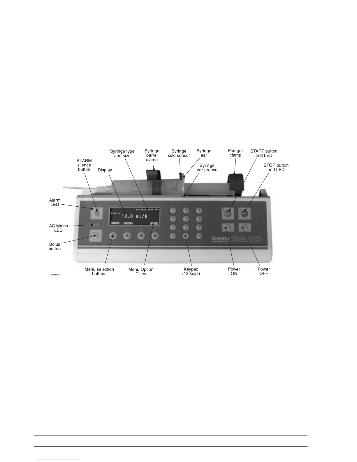
The 3400 anaesthesia syringe pump (Fig. 1.1) is based on a micro-controller design and has
been purpose developed by Graseby for the administration of anaesthetics, mainly in a hospital
operating theatre.
The pump allows a Manually Controlled Infusion, and/or a bolus to be infused using the normal
brands of syringe. The infusion entails presetting into the pump both the required infusion rate
and the dose of the drug that is going to be used.
The pump can be configured by a suitably qualified person to work with any one of several
selected brands of syringe, plus, when converted, the Braun Perfusor syringe. The particular
brand of syringe selected will be displayed.
The diameter of the syringe installed is automatically sensed by the pump and from this dimension
and knowing the syringe brand the pump is able to calculate and display the following syringe
sizes:
5; 10; 20; 30 and 60 millilitres.
The pump is a compact robust unit that is able to function either sitting on a table top or mounted
on an IV pole via the pumps pole clamp.
Introduction
Introduction
General
information
The pump can be configured to:
• deliver a volume or mass unit, manual controlled infusion, or
• a volume or mass unit bolus infusion.
A running total of the volume of liquid that has been infused is stored in the pump’s totaliser, and
will remain available for display even though the infusion may have been stopped and then
restarted. The totaliser can be set to zero when required.
The pump can be operated from AC power or from internal rechargeable batteries. When functioning on fully charged batteries, and under normal conditions, the pump gives more than ten
hours of continual use.
The AC power can vary between 100 V and 250 V and 50 to 60 Hz, thus allowing the pump to be
used anywhere in the world without adjustment.
A battery charging circuit within the pump keeps the batteries charged. The batteries are fully
charged when the AC power has been connected to the pump for 14 hours, even though the
pump itself may be switched off.
Numerous safety features have been built into both the software and the hardware, and the user
is warned of such incidents as a power failure or an occlusion by both visible and audible alarms.
The pump carries out a self-testing routine each time it is switched on.
SIMS Graseby Ltd.
1 — 2 Issue 6 (July 00) 3400 Service Manual
Figure 1.1 Front view of the 3400 pump

SIMS Graseby Ltd.
3400 Service Manual Issue 6 (July 00)
1 — 3
The main features of the 3400 are as follows:
• simple to use and easy to service,
• ergonomic styling,
• AC powered or internal battery powered,
• advanced safety features,
• a selection from several brands of syringe can be made, also the pump may be converted
to work with the Braun Perfusor 50 ml syringe,
• automatic syringe size sensing,
• a clear text display,
• a comprehensive range of alarms. For example the pump gives a
Syringe Invalid
alarm; a syringe
Nearly Empty
alarm; etc.,
• designed in consultation with users.
Features
Features
Classification
The following classification information applies to the 3400, and is to the IEC 601-1:1988
requirement.
The pump is a Class II (double insulated) device.
Also classified as internally powered equipment.
Type CF (Cardiac Floating) insulation on all inputs.
Insulation
Fluid ingress IPX1. In the normal operating position the pump is protected against drops of
water falling vertically onto it. It is not safe to use the pump in more severe wet
conditions.
Safety
(Caution)
The pump is not suitable for use in the presence of inflammable anaesthetics
mixture with air, with oxygen or nitrous oxide.
As with all computer electronic equipment, high powered electromagnetic
radiation, such as diathermy equipment in close proximity, can affect operation,
although no hazard will be caused.
Mode of
operation
Continuous.

SIMS Graseby Ltd.
1 — 4 Issue 6 (July 00) 3400 Service Manual
Graseby pumps are subject to continual development and the 3400 may, therefore, differ
slightly from the following specification:
Dimensions: 325 mm (long) x 195 mm (high) x 115 mm (deep) with the pole
clamp fitted and the plunger clamp closed.
Weight: 3.5 kg including batteries and pole clamp.
AC supply: 100 to 240 V, 50/60 Hz, 40 VA. The power supply uses Primary
Switching in order to utilise the AC supplies of most countries.
Battery type: Sealed lead acid, rechargeable (Cyclon, 3 off). SIMS Graseby
recommend that the batteries are checked at least annually (see
page 5-10).
Battery life: More than 10 hours of normal pump operation when the batteries
are fully charged. With the AC supply connected, up to 14 hours
will be required to fully recharge low voltage batteries.
Syringe BD Plastipak 5;10; 20; 30/35 or 50/60 ml.
brands: Terumo 5; 10; 20; 30/35 or 50/60 ml.
Braun Omnifix 5;10; 20; 30/35 or 50/60 ml.
Sherwood Monoject 5; 10; 20; 30/35 or 50/60 ml.
IMS Pump-jet 30 30 ml (prefilled).
Fresenius Injectomat 50 ml.
Braun Perfusor 50 ml (conversion kit required, refer
to Chapter 8).
Flow rate: Continuous; 0.1 to 400 ml/h in 0.1 ml increments.
Mass units; mg/kg/h etc.
Bolus; 0.1 to 1200 ml/h in 0.1 ml increments.
Totaliser: 0 to 999.9 ml in 0.1 ml increments.
Adjustable 1.85 kg (250 mm Hg) to 7.42 kg (1000 mm Hg).
occlusion
pressure:
Temperature Operating conditions:
range: +5° to +40°C, 30 to 75% Rh, 700 to 1060 hPa.
Storage conditions:
-40° to +70°C, 30 to 90% Rh, 700 to 1060 hPa.
Drive ± 2% when measured over a complete syringe.
accuracy:
Design IEC 601-1.
standards:
Elec. safety: Class II; Type CF.
Languages Selectable via the configuration mode (see page 2-2).
available:
Specification
Specification

SIMS Graseby Ltd.
3400 Service Manual Issue 6 (July 00)
1 — 5
Development of 3000 series
Brief history of SIMS Graseby bedside syringe pumps
MS2000
The first Graseby bedside syringe pump was the MS2000. This was a basic syringe pump capable of infusions
within the range of 0.1ml/hr to 99.9ml/hr. It had a totaliser, a limited infusion capability, a built in pole clamp and was
designed for vertical operation. The MS2000 was powered by an AC supply or its internal DC batteries. This pump
is no longer manufactured by SIMS Graseby.
PCAS
The PCAS pump was developed from the MS2000 to satisfy the growing interest in Patient Controlled Analgesia
(PCA). The PCAS was very similar to the MS2000 in both appearance and mechanical design, but utilised a
different micro-processor with the capability of running the extra features required for PCA and was eventually
replaced by the 3300 pump. A printer port was also incorporated. This pump is no longer manufactured by SIMS
Graseby.
3000
The first pump in the 3000 Series of syringe pumps was the 3000 itself. This pump was designed as a low-cost
alternative to the MS2000 and satisfied the need for a horizontally mounted pump. The 3000 did not have an internal
battery supply. This pump is no longer manufactured by SIMS Graseby.
3100
The 3100 syringe pump was developed from the 3000. It is very similar mechanically but the electronic design is
superior. Dual processors were incorporated along with a vacuum fluorescent text display and internal batteries.
The maximum infusion rate was increased to 199.9 ml/hr and different syringe sizes were able to be used (automatically sensed). Extra software features, such as the intelligent ‘near end’ alarm, were also incorporated. This is the
only pump in the 3000 Series that is not fitted with an RS232 connector.
3300
The next bedside syringe pump to be developed was the 3300. This was similar in mechanical and electronic design
to the 3100 but the features were specifically for the now more mature PCA market. A lockable syringe cover was
added for security against drug theft, a four line LC display was added, and internal history recording (1500 events)
with printout was also added. With the growth in PCA knowledge in the medical community, many more software
features were incorporated into the 3300 to aid PCA administration.
3400
The 3400 was developed (again from the 3100) to satisfy the need for a high speed infusion pump for intravenous
anaesthesia. Advances in micro-controller technology allowed the use of a single device to control all the pumps
features. The maximum infusion rate was raised to 1200.0 ml/hr and bolusing facilities were also added. Later, an
infusion rate calculation facility was added to the software.
A larger liquid crystal display was used on the 3400 with the ability to display text in different sizes, also ‘soft-keys’
were used to make the user interface simpler. The range of syringe sizes that could be used was also increased. For
more advanced applications the pump could be controlled by a computer.
(contd.)

SIMS Graseby Ltd.
1 — 6 Issue 6 (July 00) 3400 Service Manual
Development of 3000 series
Brief history (contd.)
3200
The 3200 was developed as a general purpose syringe pump. Wet-side pressure sensing, intermittent infusion
capabilities, and computer interfacing were added. The wet-side occlusion pressure monitoring made the pump
particularly suitable for use in intensive-care baby units. A large text vacuum fluorescent display was added, and the
increased syringe size range of the 3400 remained.
A DC input supply (10 V to 28 V DC) version of the 3200 is also manufactured by SIMS Graseby. This variant is
primarily intended for use in an aviation environment.
3500
There are two versions of the 3500, as follows:
1. A Manually Controlled Infusion (MCI)
only
pump.
2. An MCI
plus
a Target Controlled Infusion (TCI) pump.
The 3500 was developed from the 3400 and retains all the 3400 facilities.
The ‘MCI
plus
TCI’ pump carries out a TCI using the Diprivan drug. This version of the 3500 incorporates a Diprifusor
module manufactured by Zeneca Pharmaceuticals. A new main circuit board and new software allows the 3500 to
interface with the Diprifusor module.
A 3500 non- TCI pump can be converted to become a 3500 MCI
plus
TCI pump.
3150
The 3150 is very similar to the 3200 general purpose pump. The main difference being that the In-line (wet-side)
pressure sensing system in not available on the 3150, i.e. the pressure transducer is not fitted.

CHAPTER 2
CONFIGURATION & DIAGNOSTICS MODE,
AND THRUST ADJUSTMENTS
3400
ANAESTHESIA SYRINGE PUMP

SIMS Graseby Ltd.
3400 Service Manual Issue 6 (July 00)
2 — 1
Configuration mode
CHAPTER 2
CONFIGURATION & DIAGNOSTIC MODE,
AND THRUST ADJUSTMENTS
WARNING
The Configuration Mode must only be used by personnel who have been appropriately
trained in using the 3400.
The Configuration mode allows various parameters to be made available, which in turn
allows various settings within these parameters to be set to the values required for the
infusion.
The list shown below shows each parameter within the Configuration mode, and each
parameter is further detailed in the sections that follow:
1. Syringe brand.
2. Display language.
3. Bolus beep.
4. Preset bolus.
5. Mass units.
6. LCD contrast.
7. Baud rate.
8. Max rate.
Configuration, diagnostics and thrust adjustments

SIMS Graseby Ltd.
2 — 2 Issue 6 (July 00) 3400 Service Manual
With the AC power connected and switched on (or under internal battery power) press the
ON button. The pump will carry out its self tests and will then be in its ‘set up’ mode.
Press the second ▲ button from right and the BOLUS button simultaneously.
i.e. press
^^
▲ ^ and BOLUS simultaneously.
The display will show the following question:
BD PLASTIPAK 60
LANGUAGE = ENGLISH
NEXT CHANGE
Within two seconds press the START button to confirm that you want to enter the Configuration
mode.
A display similar to the one shown below will then appear:
Note...
If the START button is not pressed within two seconds the pump will return to its ‘set up’
mode.
Press the CHANGE button repeatedly in order to scroll through the options that are available
for each parameter. The displayed option will be retained when the NEXT menu button or the
STOP button is pressed.
The various options are retained in non-volatile memory.
Changing an
option
Moving to
the next
parameter
Press the NEXT button in order to move to the next parameter. If a new option is required
repeat the above.
Press the STOP button at any option in order to exit from the Configuration mode and return
to the ‘set up’ mode.
Configuration parameters and options that are available
WARNING
The pump must be set to operate and display the brand and size of syringe that is
going to be used. Using a different brand or size of syringe to the one that is going to
be used could lead to the incorrect amount of drug being administered, resulting in
injury or death.
1. Options: BD Plastipak
Terumo
Braun Omnifix
Monoject
IMS Pump-jet 30
Injectomat 50 ml
Braun Perfusor: a conversion kit is required, see Chapter 8.
Calling up the
Configuration
mode
CONFIGURE ?
Configuration mode
Syringe brands

SIMS Graseby Ltd.
3400 Service Manual Issue 6 (July 00)
2 — 3
2. Option: The optional display language required is selected by scrolling to it.
3. Yes or No: Set to YES if you wish the pump to beep whilst delivering a bolus. If a
bolus beep is not required then set to NO.
4. Yes or No: Set to YES if you require the option to use the preset bolus ( i.e. dose is
preset for a Hands Free bolus infusion).
Set to NO if the preset bolus is not required ( i.e. the infusion dose is
controlled by the user during the Hands On bolus infusion).
5. Yes or No: If the MASS UNITS parameter is set to YES then it will be possible to
preset the pump to deliver an infusion in mass units, e.g. mg/k/g/h etc.
If the MASS UNITS is set to NO then ml/h will be th e only selection available.
Display
language
Bolus beep
Preset bolus
dose
Mass units
6. Options: The options available are 1 to 20.
7. Rate: The rates available are...
300; 600; 1200; 2400; 4800 or 9600 Baud.
8. Options: The MAX RATE options available are:
50; 100; 200; 400; 800 or 1200 ml/h.
The software program automatically sets a maximum continuous infusion
rate that depends upon the syringe size that the pump senses; see Table 1.
This automatic continuous infusion rate will be overridden if the Configuration
MAX RATE is set below the automatic rate.
LCD contrast
Baud rate
Max Rate
For example, even though the maximum continuous infusion rate for the
BD Plastipak 50 ml syringe is 400 ml/h (see Table 2.1), if the Configuration
MAX RATE is set to, say, 200 ml/h then the syringe will only be able to infuse
at up to 200 ml/h.
Thus the Configuration MAX RATE setting can be used to control, in preset
steps, both the continuous infusion (up to 400 ml/h) and the bolus infusion
(up to 1200 ml/h).
Table 2.1 Syringe size and maximum
automatic continuous infusion rate
Syringe size Max. auto. cont.
infusion rate (ml/h)
50/60 400
30/35 400
20 400
10 200
5 100
Configuration mode

SIMS Graseby Ltd.
2 — 4 Issue 6 (July 00) 3400 Service Manual
WARNING
The Diagnostic mode must only be used by appropriately qualified personnel.
The 3400 has been designed so that the Diagnostic mode parameters will only be available if a
set sequence of pump buttons are pressed.
Diagnostic
mode
Calling up
the Diagnostic
mode
With the AC power connected and switched on (or under internal battery power) press the
ON button. The pump will carry out its self tests and will then be in its ‘set up’ mode.
Press the second ▲ button from right, and the ALARM button simultaneously.
i.e. press
^ ^
▲ ^ and the ALARM button simultaneously.
The display will show the following question:
DIAGNOSTICS ?
Within two seconds press the START button to confirm that you want to enter the Diagnostic
mode.
A display similar to the one shown below will then appear:
Note...
If the START button is not pressed within two seconds the pump will return to its ‘set up’
mode.
BD PLASTIPAK 60
VERSION 2.07
NEXT
Press the NEXT button in order to move to the next parameter.
Moving to
next parameter
The five parameters that can be viewed, by scrolling when in the Diagnostic mode, will be
similar to the displays shown below:
• VERSION = 2.06
this display shows the version of software that is installed in the pump. Note,
since the 3400 is field up-gradable via its serial port the version number on the label
of the EPROM may differ from the installed version. The displayed version is to be
taken as correct.
• CRC = CD53
this shows the Cyclic Redundancy Check (CRC).
• TOTAL VOLUME
this shows the total volume infused since the pump was manufactured.
• TOTAL HOURS
this shows the total hours that the pump has been in operation since the pump was
manufactured.
• VOLTAGE = 6.9
this shows the value of the DC voltage that is supplied to the main board.
Diagnostic
displays
Diagnostic mode

SIMS Graseby Ltd.
3400 Service Manual Issue 6 (July 00)
2 — 5
Press the STOP button when in any Diagnostic parameter in order to exit from the Diagnostic
mode.
Exiting from the
Diagnostic mode
WARNINGS
The following procedures must only be carried out by qualified personnel.
Electric shock hazard
The pump
must
be disconnected from the AC power supply before opening the
casing.
Disassembly and assembly of casing
The casing of the pump will have to be opened in order to carry out any adjustments that may
be required to the occlusion thrust, and also for various setting up and repair procedures. These
procedures are detailed in Chapters 4 and 5.
1. Disconnect the AC power connector and utilising a scratch free flat surface, turn
the pump over in order to gain access to the base of the pump.
2. Undo and retain the six screws that hold the two halves of the pump casing together.
One of the six screws is situated in a channel in the rear cover.
3. Place the pump upright and from the top carefully ease the two halves of the casing
apart, taking care not to put any strain on the internal connecting cable looms that
form a hinge between the two halves of the casing.
1. Each time the casing has been taken apart and reassembled the syringe size
functional tests detailed on page 6-1 must be carried out.
2. Being careful not to trap any leads, assemble the casing by reversing steps 2 and 3
detailed above, ensuring that the two case halves have ‘snapped’ together and that
the front and rear mating edges are equal and parallel. The screws should be
tightened to a torque of between 70 and 75 cNm, and in the order shown in the
diagram below:
Taking the
casing apart
Assembly
Disassembly of casing
1
3
2
5
GM0595-B
4
6

SIMS Graseby Ltd.
2 — 6 Issue 6 (July 00) 3400 Service Manual
Syringe
stiction
Occlusion thrust
Thrust
measurements
The two most frequently used methods to measure the point at which an occlusion occurs
are the thrust and pressure methods.
At the present time SIMS Graseby set the occlusion by using a thrust measurement procedure. This method measures the plunger clamp thrust by using a set of weights (as described below), but has the slight disadvantage that the characteristics of the syringe have to
be taken into account.
The occlusion pressure is obtained by measuring the pressure that occurs in the infusion
line. This in-line method gives a good accuracy (better than 5%) over a wide range of pressures, but also has the slight disadvantage of requiring a disposable that is unique to the
pump being measured.
The internal occlusion sensing system within the pump is always active.
The occlusion thrust checks must be carried out whenever the super nut assembly is dismantled.
Translation of the thrust depends on the syringe diameter and the stiction of the syringe. The
formula for calculating the thrust is given below:
T = P x A +S
732 1
where: T is the thrust in kg,
P is the delivery pressure in mmHg,
A is the cross sectional area of the syringe in cm2,
and S is the syringe stiction in kg.
The occlusion thrust of the pump is factory set to be between two limits (i.e. a minimum and
a maximum tolerance). The customer may reset the thrust for their own particular requirement. The thrust of a particular pump may, therefore, differ from the original factory set level.
The occlusion thrust of the 3400 pump is factory set at Graseby’s to be between
5.7 kg and 6.2 kg (767 mmHg and 834 mmHg).
Stiction for a syringe varies from brand to brand as well as from batch to batch. Stiction can
be as low as 0.1 kg and as high as 2 kg. The stiction of some syringe brands has been found
to be particularly high.
Stiction can also vary along the plunger travel and is usually lowest in small diameter syringes.
Using a sample syringe and allowing for a safety margin for sticky syringes, adjustments can
be made by measuring the thrust generated. If the stiction characteristics of a syringe are
known then by using the formula given above the occlusion thrust can be set.
Occlusion
measurements
SIMS Graseby Ltd.
3400 Service Manual Issue 6 (July 00)
2 — 7
Thrust
checks
Occlusion thrust
The thrust checks that are detailed below use the weights that correspond to the factory set
occlusion threshold levels for a 3400 (i.e. 5.7 and 6.2 kg). If a different occlusion level setting
is required then the weights will have to be adjusted accordingly.
The thrust adjustment procedures are detailed on page 2-8.
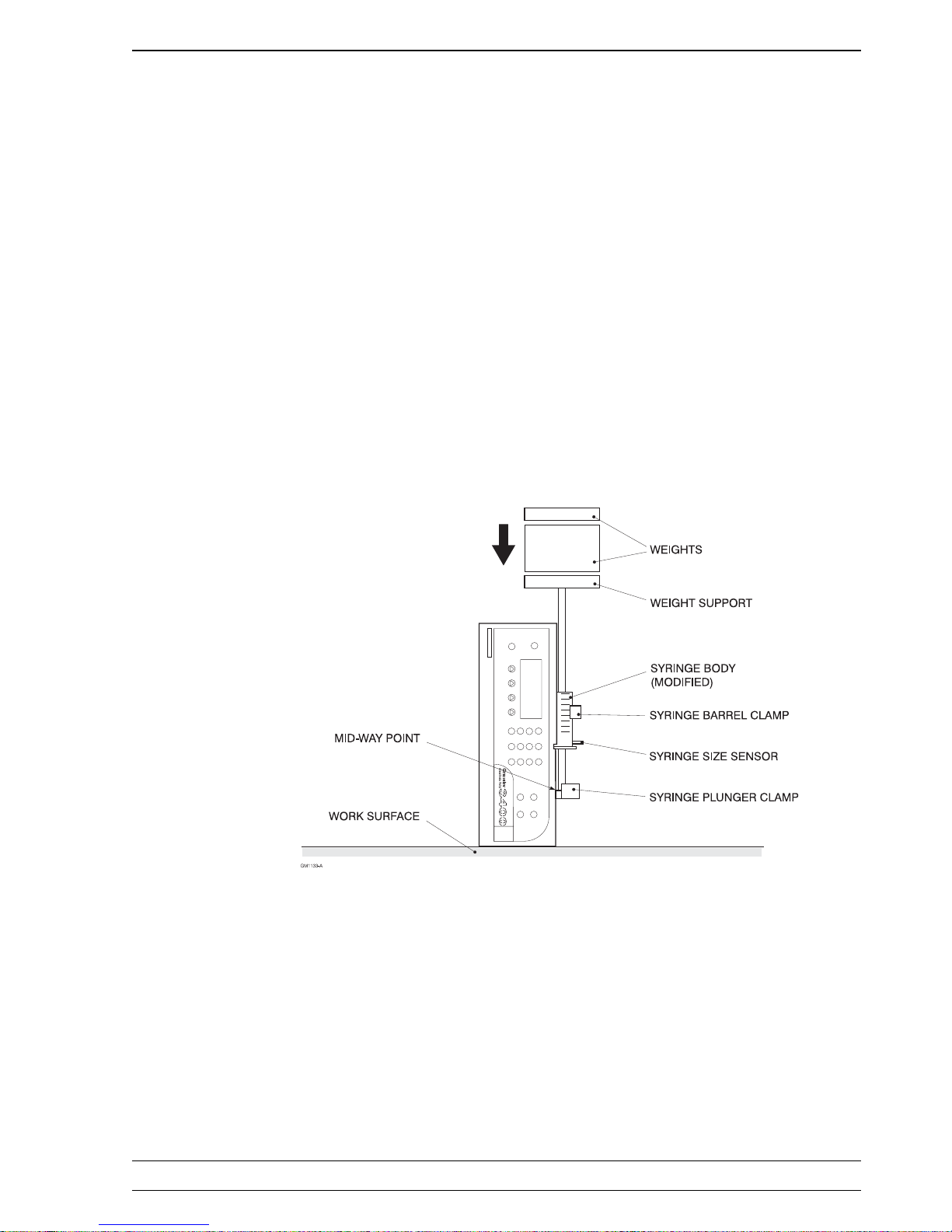
1. Set the pump's plunger clamp to approximately midway along its support tube.
2. Remove the plunger from a BD 60 ml syringe and then saw the end off the syringe (see
Fig. 2.1). Place this modified syringe onto the pump so that it will act as a guide for the
weight support rod and also position the size sensor flag.
3. With the pump switched ON, set the infusion rate to 200 ml/hr.
4. Place the pump in a vertical position, with its left hand side uppermost (see Fig. 2.1).
5. Place the weight support rod through the modified syringe and onto the pump's plunger
clamp.
6. Place a weight of 5.7 kg on top of the weight support and check that the pump
operates for at least 30 seconds and does not occlude (i.e. the alarm does not sound).
Remove the weight.
7. Place a weight of 6.2 kg on top of the weight support and check that within 30
seconds the pump does occlude (i.e. the alarm sounds).
Figure 2.1 Thrust measuring set up

SIMS Graseby Ltd.
2 — 8 Issue 6 (July 00) 3400 Service Manual
If the occlusion thrust requires adjustment then the following procedures will have to be carried out:
1. Switch the pump off and disconnect the AC supply.
2. Take the casing apart as detailed on page 2-5.
3. If necessary rotate the leadscrew to reveal the grub screw that is located on the occlusion
adjusting nut. Loosen the grub screw with a 1.5 mm hexagonal key.
4. Alter the setting of the occlusion adjusting nut as necessary. One full turn of the adjusting
nut using a 50\60 ml syringe gives approximately 2.73 kg (369 mmHg) of adjustment.
Rotating the adjusting nut in order to decrease the tension on the leadscrew spring will
decrease the pump's occlusion setting.
Rotating the adjusting nut in order to increase the tension on the leadscrew spring will
increase the pump's occlusion setting.
5. Tighten the grub screw.
6. Temporarily assemble the two halves of the pump, being careful not to trap any leads.
7. Carry out the thrust checks detailed on page 2-7.
8. In order to obtain the thrust required it may be necessary to repeat steps 2 to 7 above.
9. Finalise the assembly of the pump casing (see page 2-5).
10. Carry out tests No 9 and 10 detailed in the functional test procedures (see page 6-3).
Thrust
adjustments

CHAPTER 3
FUNCTIONAL DESCRIPTIONS
3400
ANAESTHESIA SYRINGE PUMP

SIMS Graseby Ltd.
3400 Service Manual
Issue 6 (July 00)
3 — 1
Functional descriptions
CHAPTER 3
FUNCTIONAL DESCRIPTIONS
This Chapter explains how the 3400 operates. Reading this chapter will help a technician
to rectify any possible faults that may occur within the pump.
The functional descriptions of the pump may be divided into five separate areas, and each
of these functional descriptions have been detailed separately in the descriptions that
follow:
• Drive system.
• Occlusion sensing system.
• Electro/mechanical control system.
• Sensing (alarm) systems.
• Software.
Introduction
The motor, gearbox, leadscrew and associated components (see Fig. 7.1) are mounted on a
glass reinforced polycarbonate casing. The strength of this casing enables a precise mechanical
location to be achieved for the various components.
Both the inner and outer metal tubes are made of substantial material in order to eliminate all
unwanted flexing.
The drive system comprises a DC motor working through a gearbox in order to rotate a
leadscrew. A half nut assembly engages onto the leadscrew, and the assembly is also connected to a steel tube. The steel tube is in turn connected to the plunger clamp.
As the motor spindle rotates the
leadscrew
rotates and the
half nut assembly
travels to the
left, along the
leadscrew
. The
half nut assembly
pulls the outer of two steel tubes to the left.
This outer tube travels over and along a support tube; the support tube is the length of the
pump. The plunger clamp moves with the outer tube pushing ‘in’ the syringe plunger.
Drive system
DC motor
and
leadscrew
The DC voltage applied to the motor is derived from a pulse width modulated output from the
processor.
A spring-loaded toggle mechanism is attached to the bottom of the half nut. This toggle
mechanism enables the plunger clamp to be physically swung ‘in or out’ thus rotating the
outer metal tube so that the half nut is either fully ‘engaged or disengaged’ (respectively) from
the leadscrew.
When the plunger clamp is pulled down the
half nut
engages with the
leadscrew,
and the
clamp itself engages with the end of the syringe.
The syringe plunger slots into place behind a slotted pair of lips. These lips prevent the
syringe plunger from moving forward in the event of negative pressure on the syringe.
Two small push-buttons on the edge of the plunger clamp make contact with the top of the
syringe plunger. These push-buttons control the operation of a
lever
which protrudes from
the plunger clamp.
Processor
Plunger
clamp
Toggle
mechanism
 Loading...