

Page 1

EQ 55 OPERATORS MANUAL
950-70017001
Issue 1.2 February 1998
Page 2

Page 3

KONGSBERG SIMRAD MESOTECH LTD.
WARRANTY STATEMENT
Kongsberg Simrad Mesotech Ltd. warrants that its products are free from defective
materials and/or workmanship for a period of 12 months from the date of receipt of goods
by the purchaser, or 18 months from date of product shipment from the manufacturing
facility (which ever occurs first). Kongsberg Simrad Mesotech will - at no charge - repair or
replace (at its option) any part(s) determined to be defective of workmanship or materials,
provided the warranty claim is made to either the manufacturing facility, or its authorized
repair centres within the warranty period.
The purchaser is responsible for the examination of the product upon receipt. The
purchaser is required to report any irregularity to received Kongsberg Simrad Mesotech
goods to either the manufacturer - its Sister companies - or Agents, within 15 days of
receipt of goods. Proof of date received may be required.
The warranty is void if warranty labels are broken; Kongsberg Simrad Mesotech will not
warrant any product which is physically damaged, abused, altered, subjected to accident or
negligence or misuse, or is incorrectly installed or used by the purchaser - or purchaser's
representative.
Consumable items (including lamps, fuses, and worn O rings or shaft-seals) are excluded
by the warranty.
Kongsberg Simrad Mesotech cannot warrant that its products are suitable for any
particular or intended purpose. No other warranty is expressed or implied; Kongsberg
Simrad Mesotech accepts no liability of consequential damages. Consequential damages
include, but are not limited to: loss of profit, property damage, personal injury.
The maximum liability shall not, in any case, exceed the price of the product claimed to be
defective.
Kongsberg Simrad Mesotech Ltd.
Port Coquitlam, BC - Canada
Page 4

Page 5

EQ 55 Operators Manual 950-70017001/1.
2
List of Contents Page 1
LIST OF CONTENTS
Part 1
Part 2
Part 3
Part 4
Part 5
Part 6
Part 7
Part 8
..........................................................
........................................................................................
.......................................................................................
...............
...............................
.....................................................................................
.........................................................................................
.........................................................................................
Appendix A
Appendix B
Introduction and System Familiarization
Operation of the EQ55
Principles of Operation
Installation Instructions for the EQ-55, Drawer, and Stand Alone
Maintenance, Troubleshooting, Repair and Spare Parts
Technical Information
Servicing the EQ-55
Electrical Drawings
......................................................................................
..................................................................................................
Default Settings
Glossary
Kongsberg Simrad Mesotech Ltd.
Port Coquitlam, BC - Canada
Page 6

950-70017001/1.2 EQ 55 Operators Manua
l
s
Page 2 List of Content
Kongsberg Simrad Mesotech Ltd.
Port Coquitlam, BC - Canada
Page 7

EQ 55 Operators Manual 950-70017001/1.
2
3
List of Contents Page
MODIFICATION RECORD
EQ 55 OPERATORS MANUAL
950-70017001
Issue: 1.2
February 1998
Issue
No. Date Initial Comments
1.2 02.98 Update
1.1 06.97 Update
1.0 10.96 Update
Draft 09.96 First Release
To assist us in making improvements to the product and this document, Simrad
Mesotech welcomes comments and constructive criticisms. Please send all such
comments, in writing, to:
Kongsberg Simrad Mesotech Ltd.
Documentation Department
1598 Kebet Way
Port Coquitlam, BC V3C 5M5
CANADA
Kongsberg Simrad Mesotech Ltd.
Port Coquitlam, BC - Canada
Page 8

950-70017001/1.2 EQ 55 Operators Manua
l
s
Page 4 List of Content
Kongsberg Simrad Mesotech Ltd.
Port Coquitlam, BC - Canada
Page 9

EQ-55 Operators Manual 950-7001001/Iss1.
2
Introduction and System Familiarization Page 1.1
PART 1
INTRODUCTION AND SYSTEM
FAMILIARIZATION
1. INTRODUCTION AND SYSTEM F AMIL IARIZAT ION............................ 1.3
1.1 INTRODUCTION AND SYSTEM FAMILIARIZATION............................1.3
1.2 SAFETY SUMMARY...................................................................................1.3
1.2.1 Fuse and Power Cord............................................................................1.3
1.2.2 Grounding.............................................................................................1.3
1.2.3 Safety Statements.................................................................................1.4
1.2.4 Lifting and Carrying.............................................................................1.4
1.2.5 Installation............................................................................................1.4
1.2.6 Getting Started (Quick Start)...............................................................1.4
1.2.7 Safety Procedures.................................................................................1.4
1.3 INSTALLATION .........................................................................................1.4
1.4 GLOSSARY OF TERMS ............................................................................. 1.4
1.5 OPERATION ...............................................................................................1.5
1.5.1 Maintenance..........................................................................................1.5
1.5.2 Troubleshooting....................................................................................1.5
1.5.3 Repair and Service................................................................................1.5
1.5.4 Principles of Operation......................................................................... 1.5
1.5.5 Default Settings....................................................................................1.5
1.6 SUMMARY OF EQ 55 FEATURES............................................................1.6
1.6.1 Display Screen Size...............................................................................1.6
1.6.2 Display Screen Resolution....................................................................1.6
1.6.3 Display Screen Colors...........................................................................1.6
1.6.4 Information on the Display Screen.......................................................1.6
1.6.5 Time Marker - Minute Increments.......................................................1.6
1.6.6 Auto Range Function............................................................................1.6
1.6.7 Units of Measure...................................................................................1.7
1.6.8 Expansion Ranges .................................................................................1.7
1.6.9 Color Threshold.....................................................................................1.7
Kongsberg Simrad Mesotech Ltd.
Port Coquitlam, BC - Canada
Page 10

950-7001001/Iss1.2 EQ-55 Operators Manua
l
n
Page 1.2 Introduction and System Familiarizatio
1.6.10 Phased Range......................................................................................1.7
1.6.11 Transmit Power Reduction.................................................................1.7
1.6.12 Ranges................................................................................................. 1.7
1.6.13 Dual VRM............................................................................................ 1.7
1.6.14 Other Features....................................................................................1.8
Kongsberg Simrad Mesotech Ltd.
Port Coquitlam, BC - Canada
Page 11

EQ-55 Operators Manual 950-7001001/Iss1.
2
3
Introduction and System Familiarization Page 1.
1. INTRODUCTION AND SYSTEM
FAMILIARIZATION
1.1 INTRODUCTION AND SYSTEM FAMILIARIZATION
Welcome to SIMRAD's EQ 55 Echo sounder. The EQ 55 is a totally new echo
sounder that can be used in any fishery in the world and is fully contained in just
one cabinet. Several different configurations of transducers can be purchased
separately for the EQ 55.
In this beginning chapter you will find an important section on safety
precautions, a "getting started" section that helps you locate the information
you need, and a section that summarizes the features built into the EQ 55.
Although this manual can be read in any sequence, we strongly encourage all
users to first read the Safety Summary. It is also advisable for experienced users
to at least scan the whole manual to find out what information is available when a
question does arise.
WARNING: CHANGES OR MODIFICATIONS NOT EXPRESSLY
APPROVED BY SIMRAD MESOTECH. MAY VOID YOUR WARRANTY
AND MAY CAUSE INCREASED RADIO FREQUENCY EMISS IONS.
1.2 SAFETY SUMMARY
1.2.1 Fuse and Power Cord
Note that the appropriate fuses must be employed. Ensure that the power
cord is firmly attached to the line filter on the rear panel.
1.2.2 Grounding
The EQ 55 is a sophisticated piece of electronic equipment. To reduce risk of
electrical shock, properly ground the unit to the ship's ground using the wing nut
ground stud on the back of the unit.
Kongsberg Simrad Mesotech Ltd.
Port Coquitlam, BC - Canada
Page 12

950-7001001/Iss1.2 EQ-55 Operators Manua
l
n
Page 1.4 Introduction and System Familiarizatio
1.2.3 Safety Statements
This manual contains boxed information that notifies, cautions or WARNS about
various actions. Take note of what they say.
1.2.4 Lifting and Carrying
Use proper lifting and carrying techniques when moving and installing the EQ 55.
1.2.5 Installation
Follow the installation instructions in Chapter 4 for proper, safe installation of the
EQ-55. Ensure that the surface that the EQ 55 is mounted to is able to support
the weight of the equipment, especially in rough weather.
1.2.6 Getting Started (Quick Start)
This section provides the user with a short, quick overview of the EQ 55 manual.
1.2.7 Safety Procedures
The EQ 55 is an electrical device. For your safety and the safety of your crew and
vessel we strongly advise you to read Section 1.1 - Safety Summary.
1.3 INSTALLATION
Turn to Chapter 4 - Installation for correct procedures to use in installing the
EQ 55.
1.4 GLOSSARY OF TERMS
If you have never used an echo sounder before or if you are unsure of how a term
is used in this manual, then turn to Appendix B - Glo ssary of T erms.
Kongsberg Simrad Mesotech Ltd.
Port Coquitlam, BC - Canada
Page 13

EQ-55 Operators Manual 950-7001001/Iss1.
2
Introduction and System Familiarization Page 1.5
1.5 OPERATION
If you are not familiar with the operation of the EQ 55, turn to Chapter 2 Operating the EQ-55.
1.5.1 Maintenance
Like all pieces of equipment, the EQ 55 needs to be properly maintained. Check
Section 5.1 Preventive Maintenance for details.
1.5.2 Troubleshooting
If, after following the instructions in Section - Operation of the EQ 55, you still
experience difficulties operating the EQ 55, check with Section 5.2 -
Troubleshooting.
1.5.3 Repair and Service
In the event the EQ 55 fails to operate, see Section 5.3 - Repair and Service for
instructions.
1.5.4 Principles of Operation
The scientific principles of the operation of the EQ 55 are explained in Chapter 3
- Principles of Operation.
1.5.5 Default Settings
The factory settings for the EQ 55 can be found in Appendix A - Default
Settings. Included in this section is information on how to reset all the EQ 55
functions to their default settings.
Kongsberg Simrad Mesotech Ltd.
Port Coquitlam, BC - Canada
Page 14

950-7001001/Iss1.2 EQ-55 Operators Manua
l
n
Page 1.6 Introduction and System Familiarizatio
1.6 SUMMARY OF EQ 55 FEATURES
1.6.1 Display Screen Size
14 inches (356 mm) diagonal (nominal)
1.6.2 Display Screen Resolution
640 (horizontal) x 480 (vertical) pixels, .29 mm dot pitch
1.6.3 Display Screen Colors
• Sixteen colors, including background color. Scale lines, depth readings and
setting indication will be white.
• Background color selections are blue and black.
• Targets are displayed in 12 colors.
1.6.4 Information on the Display Screen
• Digital scale and digital depth
• 12 color echo strength sample scale
• Ship speed (when optional sensor is employed)
• Water temperature (when optional sensor is employed)
• Ship's position (when position is available via NMEA interface)
1.6.5 Time Marker - Minute Increments
A time marker moves across the top of the screen as a blue bar/light blue bar in 60
second increments.
1.6.6 Auto Range Function
In Auto Range Mode, the range increase and decreases to keep the bottom always
on the display screen.
Kongsberg Simrad Mesotech Ltd.
Port Coquitlam, BC - Canada
Page 15

EQ-55 Operators Manual 950-7001001/Iss1.
2
7
Introduction and System Familiarization Page 1.
1.6.7 Units of Measure
Meters, fathoms, passi braza and feet.
1.6.8 Expansion Ranges
The EQ 55 can display one of five different Expansion Ranges that are close ups of
the bottom or VRM and are displayed across the lower third of the display screen.
1.6.9 Color Threshold
Up to 8 weak echo colors may be erased one at a time to suppress weak and
unwanted echoes.
1.6.10 Phased Range
The "start" range, shown at the top of the screen, can be selected.
1.6.11 Transmit Power Reduction
Full Power (1)
Medium Power (1/10)
Low Power (1/100)
1.6.12 Ranges
One of 20 ranges can be selected.
1.6.13 Dual VRM
Variable Range Markers (VRM) for each frequency allows measurement of depth
to targets.
Kongsberg Simrad Mesotech Ltd.
Port Coquitlam, BC - Canada
Page 16

950-7001001/Iss1.2 EQ-55 Operators Manua
l
n
Page 1.8 Introduction and System Familiarizatio
1.6.14 Other Features
Gain, STC, White Line, Control Memory,, Brightness & Contrast Controls, Bottom
Lock, AScope, Alarms, Adjustable Scroll Speed, Event Markers, Selectable
Language, Optional
Color Printer.
Kongsberg Simrad Mesotech Ltd.
Port Coquitlam, BC - Canada
Page 17

EQ-55 Operators Manual 950-7001001/Iss 1.
2
Operation of the EQ-55 Page 2.1
PART 2
OPERATION OF THE EQ-55
2. OPERATION OF THE EQ 55 ...................................................................... 2.3
2.1 BASIC OPERATION OF THE EQ 55.........................................................2.3
2.1.1 Turning the EQ 55 On..........................................................................2.3
2.1.2 Joystick..................................................................................................2.3
2.2 MENU SELECTIONS.................................................................................2.5
2.2.1 Main Menu............................................................................................2.5
2.2.2 Low and High Frequency Menu...........................................................2.6
2.2.3 Low or High Frequency - Manual Range.............................................2.7
2.2.4 Low or High Frequency - Manual Phase..............................................2.8
2.2.5 Low or High Frequency - Auto Range ..................................................2.9
2.2.6 Low or High Frequency - Auto Phase.................................................2.10
2.2.7 Low or High Frequency - Set Auto Phase..........................................2.11
2.2.8 Low or High Frequency - Set VRM (Variable Range Marker) ..........2.12
2.3 DISPLAY
2.3.1 Display Mode - LF OR HF..................................................................2.14
2.3.2 Display Mode - LF OR HF/ASCOPE..................................................2.15
2.3.3 Display Mode - DUAL/VERT (Dual Vertical) ....................................2.16
2.3.4 Display Mode - DUAL/HORZ (Dual Horizontal)................................2.17
2.3.5 Display Mode - Navigation .................................................................2.18
2.4 EXPANSION MENU.................................................................................2.19
2.4.1 Expansion - Bottom Exp. (Bottom Expansion) ..................................2.20
2.4.2 Expansion - VRM EXP (VRM Expansion)..........................................2.21
2.4.3 Expansion - EXP RANGE (Expansion Range)...................................2.22
2.4.4 Set Marker Menu................................................................................2.23
2.5 GAIN MENU.............................................................................................2.24
2.5.1 Gain - LF and HF Gain.......................................................................2.25
2.6 TRANSMIT POWER MENU.....................................................................2.26
MODE MENU ..........................................................................2.13
Kongsberg Simrad Mesotech Ltd.
Port Coquitlam, BC - Canada
Page 18

950-7001001/Iss 1.2 EQ-55 Operators Manua
l
Page 2.2 Operation of the EQ-55
2.7 CONFIGURATION MENU.......................................................................2.27
2.7.1 Configuration- Units of Measure........................................................ 2.28
2.7.2 Configuration - Background Color......................................................2.29
2.7.3 Configuration - Language...................................................................2.30
2.7.4 Configuration - EXT I/F (External Interface) Sub-menu...................2.31
2.7.5 Configuration - EXT I/F - NMEA 0183...............................................2.32
2.7.6 Configuration - EXT I/F - Printer.......................................................2.33
2.7.7 Configuration - EXT I/F - Ship's Speed..............................................2.34
2.7.8 Configuration - EXT I/F - Water Temperature..................................2.35
2.7.9 Configuration - EXT I/F - Trigger.......................................................2.36
2.7.10 Configuration - Test Pattern............................................................2.37
2.7.11 Configuration - TVG (Time Varying Gain).......................................2.38
2.7.12 Configuration - Color Threshold.......................................................2.39
2.7.13 Configuration - Scroll Speed.............................................................2.40
2.7.14 Configuration - Alarms Sub-menu...................................................2.41
2.7.15 Configuration - Alarms - Set Min Depth (Set Minimum Depth).....2.42
2.7.16 Configuration - Alarms - Set Max Depth (Set Maximum Depth)....2.43
2.7.17 Configuration - Alarms - Min and Max Alarms ON/OFF................2.44
2.7.18 Configuration - White Line...............................................................2.45
2.7.19 Configuration - Filter........................................................................2.46
2.7.20 Configuraiton - STC (Sensitivity Time Control)..............................2.47
2.7.21 Configuration - Depth Adjust (Depth Adjustment) .........................2.48
2.7.22 Configuration - Sound Velocity.........................................................2.49
2.7.23 Configuration - Save Settings...........................................................2.50
2.7.24 Configuration - Load Settings ..........................................................2.51
Kongsberg Simrad Mesotech Ltd.
Port Coquitlam, BC - Canada
Page 19

EQ-55 Operators Manual 950-7001001/Iss 1.
2
3
Operation of the EQ-55 Page 2.
2. OPERATION OF THE EQ 55
2.1 BASIC OPERATION OF THE EQ 55
The EQ 55 is an easy to use echo sounder whose functions are quickly accessible
through on-screen menus by means of a joystick.
Caution: Do not operate the EQ 55 with the transducers
out of the water. Operation at full transmit power with
the transducers out of the water risks permanent
damage to the transducers.
2.1.1 Turning the EQ 55 On.
The EQ 55 is turned on by pressing the rocker switch in the lower left hand corner
of the control panel.
2.1.2 Joystick
The EQ 55 is controlled through menus that you access by operating a joystick
located on the control panel. Below is a list of what happens when you move the
joystick. If you get lost in the menus, repeatedly push the joystick to the left, this
will move you up to each previous menu until you arrive at the MAIN MENU. To
make the MAIN MENU reappear push the joystick once to the right.
Kongsberg Simrad Mesotech Ltd.
Port Coquitlam, BC - Canada
Page 20

950-7001001/Iss 1.2 EQ-55 Operators Manua
l
Page 2.4 Operation of the EQ-55
Pushing the joystick UP causes the cursor
highlight to move up the selected menu.
Pushing the joystick
to the LEFT causes
the cursor highlight to
move to the previous
menu.
Pressing the joystick DOWN causes the cursor
highlight to move down the selected menu.
Pushing the joystick to
the RIGHT selects the
highlighted function.
Kongsberg Simrad Mesotech Ltd.
Port Coquitlam, BC - Canada
Page 21

EQ-55 Operators Manual 950-7001001/Iss 1.
2
Operation of the EQ-55 Page 2.5
2.2 MENU SELECTIONS
The EQ 55 is operated by making selections from various on-screen menus. This
section explains what each menu listing means or does. To select a function, move
the joystick up or down so the highlight is on the item you want, then press the
joystick to the right to highlight and select the function.
Note: In this chapter each menu selection is illustrated with its menu. The
highlight is shown as shaded text. The menu being described is shown
larger, any previous menus are shown smaller and in sequence as
indicated by arrows. The previous menus also have highlighted text
that follows the path taken to the present function. This allows you to
see the menu selections necessary to select a particular function.
2.2.1 Main Menu
MAIN MENU
LF SETTING
HF SETTING
DISPLAY MODE
EXPANSION
SET MARKER
GAIN
TRANSMIT POWER
CONFIGURATION
The Main Menu is the starting point for making menu
selections for the EQ 55.
Note: When the Main Menu is displayed, moving the
joystick to the LEFT will remove t he Main Men u from t h e
display screen. Moving the joystick once more to the
LEFT will also remove the Statu s W ind o w from t h e
display screen. Moving the joystick to the RIGHT
will restore the Status Window, and moving the joystick
once more to the RIGHT will restore the Main Menu.
Kongsberg Simrad Mesotech Ltd.
Port Coquitlam, BC - Canada
Page 22

950-7001001/Iss 1.2 EQ-55 Operators Manua
l
Page 2.6 Operation of the EQ-55
2.2.2 Low and High Frequency Menu
MAIN MENU
LF SETTINGS
HF SETTINGS
DISPLAY MODE
EXPANSION
SET MARKER
GAIN
TRANSMIT POWER
CONFIGURATION
↓↓↓↓
LF SETTINGS
MANUAL RANGE
MANUAL PHASE
AUTO RANGE OFF
AUTO PHASE OFF
SET AUTO PHASE
SET VRM
Selecting LF or HF Settings from the Main Menu
will take you to the Low Frequency (LF) Settings
Menu or to the High Frequency (HF) menu.
These Menus allow you to configure the Range and
Expansion functions of the Frequency channel of
the EQ-55.
The selections available in the LF and HF Settings
Menus are described on the following pages.
Kongsberg Simrad Mesotech Ltd.
Port Coquitlam, BC - Canada
Page 23

EQ-55 Operators Manual 950-7001001/Iss 1.
2
7
Operation of the EQ-55 Page 2.
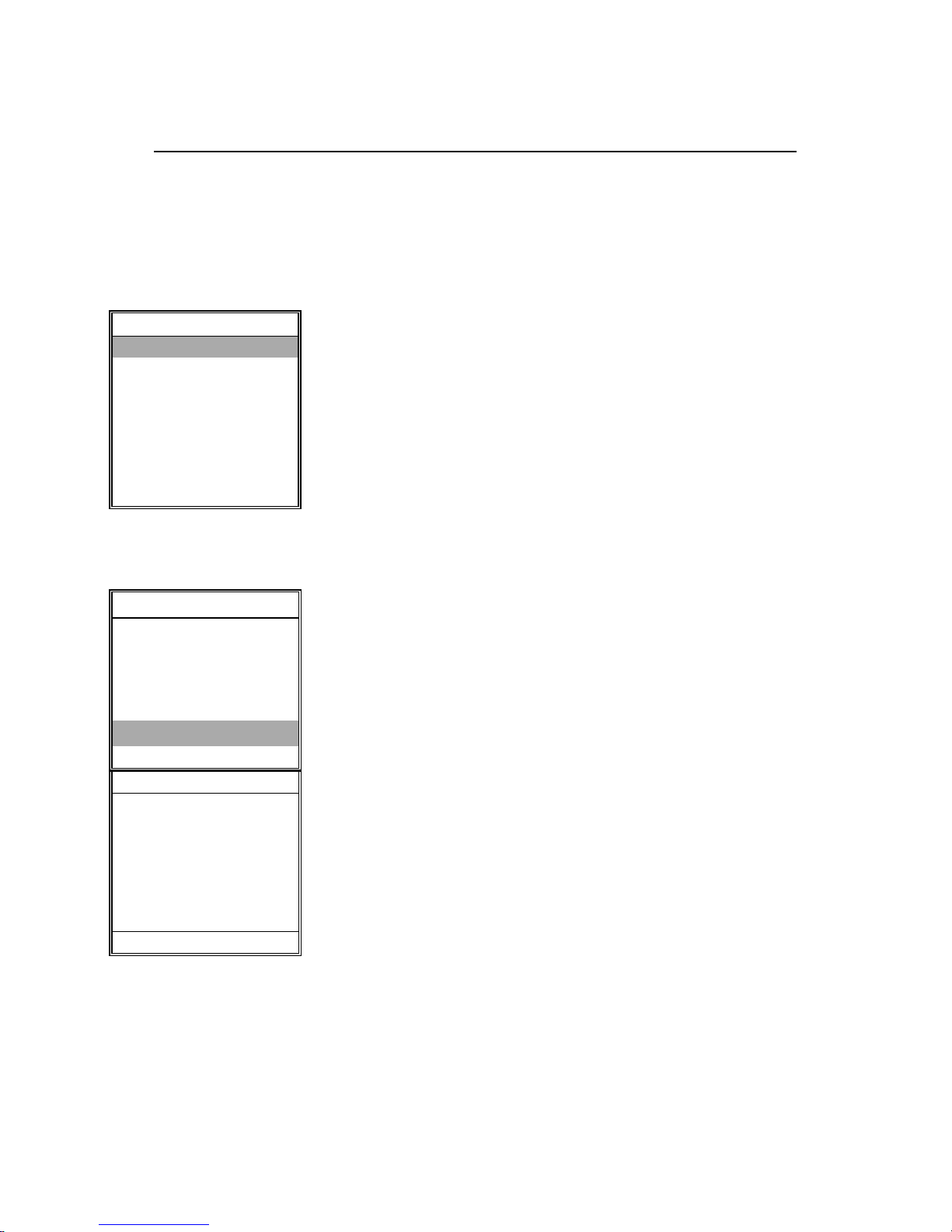
2.2.3 Low or High Frequency - Manual Range
MAIN MENU
LF SETTING
HF SETTING
DISPLAY MODE
EXPANSION
SET MARKER
GAIN
TRANSMIT POWER
CONFIGURATION
↓↓↓↓
LF SETTINGS
MANUAL RANGE
MANUAL PHASE
AUTO RANGE OFF
AUTO PHASE OFF
SET AUTO PHASE
SET VRM
Selecting Manual Range from the LF or HF Settings
Menu allows you to adjust the range displayed in
the channel.
The selection window displays maximum and
minimum ranges. The selected range can be
changed by moving the j oystick up or down.
The selected range is shown between the maximum
and minimum values possible. Once the desired
range is shown, press the joystick to the right to
take the selection.
RANGE
2000
Ù
40
Ú
20
STATUS
Kongsberg Simrad Mesotech Ltd.
Port Coquitlam, BC - Canada
Page 24

950-7001001/Iss 1.2 EQ-55 Operators Manua
l
Page 2.8 Operation of the EQ-55
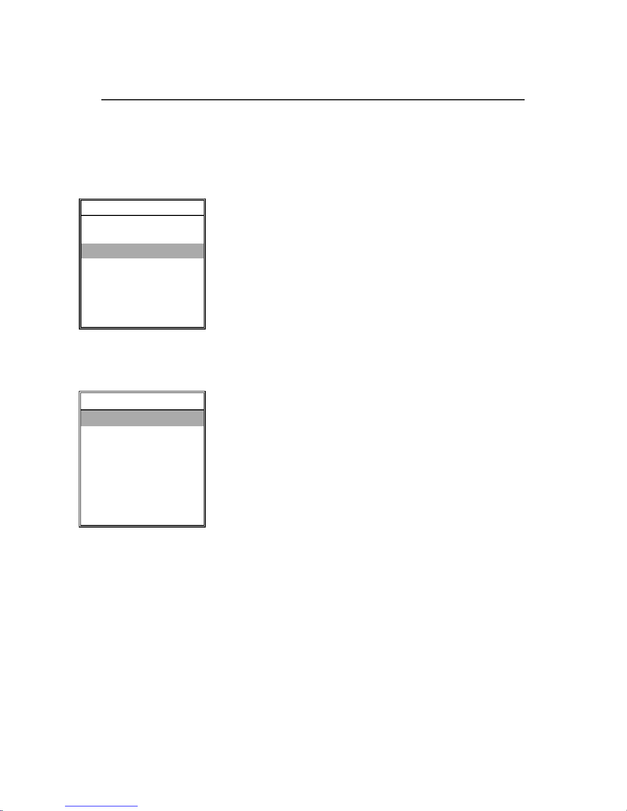
2.2.4 Low or High Frequency - Manual Phase
MAIN MENU
LF SETTING
HF SETTING
DISPLAY MODE
EXPANSION
SET MARKER
GAIN
TRANSMIT POWER
CONFIGURATION
The phased range allows you to view a selected
"window" below your vessel. The "manua l" ra n g e
(set above) determines the vertical size of the
"window." The "phase" range determines the
depth of the upper edge of the " window."
↓↓↓↓
The selection window displays the "start" range.
LF SETTINGS
MANUAL RANGE
MANUAL PHASE
AUTO RANGE OFF
AUTO PHASE OFF
SET AUTO PHASE
SET VRM
The range can be changed by moving the joystick
up or down. Once the correct range is shown in
the selection window, press the joystick to the right
to make your selection.
PHASE
40
Ù
0
Ú
0
STATUS
Kongsberg Simrad Mesotech Ltd.
Port Coquitlam, BC - Canada
Page 25

EQ-55 Operators Manual 950-7001001/Iss 1.
2
9
Operation of the EQ-55 Page 2.
2.2.5 Low or High Frequency - Auto Range
MAIN MENU
LF SETTING
HF SETTING
DISPLAY MODE
EXPANSION
SET MARKER
GAIN
TRANSMIT POWER
CONFIGURATION
↓↓↓↓
LF SETTINGS
MANUAL RANGE
MANUAL PHASE
AUTO RANGE OFF
AUTO PHASE OFF
SET AUTO PHASE
SET VRM
By selecting the Auto Range, the EQ 55 will
automatically adjust the displayed range, keeping
the display of the sea bottom in the lower half of the
screen display.
Kongsberg Simrad Mesotech Ltd.
Port Coquitlam, BC - Canada
Page 26

950-7001001/Iss 1.2 EQ-55 Operators Manua
l
Page 2.10 Operation of the EQ-55
2.2.6 Low or High Frequency - Auto Phase
MAIN MENU
LF SETTING
HF SETTING
DISPLAY MODE
EXPANSION
SET MARKER
GAIN
TRANSMIT POWER
CONFIGURATION
Selecting the Auto Phase provides a
combination of Expansion and Bottom Lock. In
this mode, the selected Auto Phase range
will be shown as a window. The window will be
automatically "phased" up or down to keep the
bottom in the window. This mode can be
especially useful when used with Bottom
Expansion. See page 8 for set AUTO PHASE
range
↓↓↓↓
Note: When Auto Phase is selected, Auto
LF SETTINGS
MANUAL RANGE
MANUAL PHASE
AUTO RANGE OFF
AUTO PHASE OFF
SET AUTO PHASE
SET VRM
Range is turned ON. Turning Auto Range OFF
will disable Auto Phase.
Kongsberg Simrad Mesotech Ltd.
Port Coquitlam, BC - Canada
Page 27
EQ-55 Operators Manual 950-7001001/Iss 1.
2
Operation of the EQ-55 Page 2.11
2.2.7 Low or High Frequency - Set Auto Phase
MAIN MENU
LF SETTING
HF SETTING
DISPLAY MODE
EXPANSION
SET MARKER
GAIN
TRANSMIT POWER
CONFIGURATION
↓↓↓↓
LF SETTINGS
MANUAL RANGE
MANUAL PHASE
AUTO RANGE OFF
AUTO PHASE OFF
SET AUTO PHASE
SET VRM
RANGE
100
Selecting the Set Auto Phase allows the user to
specify the depth off of the bottom that he wishes to
display. This range can be set between the ranges
of 10 and 100 Meters at specific increments.
Note: Set Auto Phase is used in conjunction
when Auto Phase is in the on position.
Ù
0
Ú
0
STATUS
Kongsberg Simrad Mesotech Ltd.
Port Coquitlam, BC - Canada
Page 28

950-7001001/Iss 1.2 EQ-55 Operators Manua
l
Page 2.12 Operation of the EQ-55
2.2.8 Low or High Frequency - Set VRM (Variable Range Marker)
MAIN MENU
LF SETTING
HF SETTING
DISPLAY MODE
EXPANSION
SET MARKER
GAIN
TRANSMIT POWER
CONFIGURATION
Set VRM places a horizontal white line at a selected
location. The use of a VRM allows you to measure
the depth to any displayed target.
Use the joystick to highlight SET VRM, then press
the joystick to the right to make the selection. Now,
moving the joystick up or down will move the white
VRM line, and the VRM depth will be shown in the
STATUS window.
↓↓↓↓
LF SETTINGS
MANUAL RANGE
MANUAL PHASE
AUTO RANGE OFF
AUTO PHASE
SET VRM
LF VRM
Ù
Ú
STATUS
Kongsberg Simrad Mesotech Ltd.
Port Coquitlam, BC - Canada
Page 29
EQ-55 Operators Manual 950-7001001/Iss 1.
2
3
Operation of the EQ-55 Page 2.1
2.3 DISPLAY MODE MENU
MAIN MENU
LF SETTING
HF SETTING
DISPLAY MODE
EXPANSION
SET MARKER
GAIN
TRANSMIT POWER
CONFIGURATION
↓↓↓↓
DISPLAY MODE
LF
LF/ASCOPE
HF
HF/ASCOPE
DUAL/VERT
DUAL/HORZ
NAVIGATION
Selecting Display Mode from the Main Menu will
show the possible modes for displaying the
information the EQ 55 provides.
Each selection in Display Mode is described on the
following pages.
Kongsberg Simrad Mesotech Ltd.
Port Coquitlam, BC - Canada
Page 30

950-7001001/Iss 1.2 EQ-55 Operators Manua
l
Page 2.14 Operation of the EQ-55
2.3.1 Display Mode - LF OR HF
MAIN MENU
LF SETTING
HF SETTING
DISPLAY MODE
EXPANSION
SET MARKER
GAIN
TRANSMIT POWER
CONFIGURATION
↓↓↓↓
DISPLAY MODE
LF
LF/ASCOPE
HF
HF/ASCOPE
DUAL/VERT
DUAL/HORZ
NAVIGATION
The LF or HF selection of Display Mode dedicates
the entire EQ 55 display screen to the display of
data from the chosen Frequency channel.
The other transmitter is disabled.
Kongsberg Simrad Mesotech Ltd.
Port Coquitlam, BC - Canada
Page 31

EQ-55 Operators Manual 950-7001001/Iss 1.
2
Operation of the EQ-55 Page 2.15
2.3.2 Display Mode - LF OR HF/ASCOPE
MAIN MENU
LF SETTING
HF SETTING
DISPLAY MODE
EXPANSION
SET MARKER
GAIN
TRANSMIT POWER
CONFIGURATION
↓↓↓↓
DISPLAY MODE
LF
LF/ASCOPE
HF
HF/ASCOPE
DUAL/VERT
DUAL/HORZ
NAVIGATION
In ASCOPE mode, the Frequency channel is
normally shown on the left side of the display screen
and an ASCOPE display is shown on the right side.
ASCOPE expands the latest ping into a bar graph.
The other transmitter is disabled.
Kongsberg Simrad Mesotech Ltd.
Port Coquitlam, BC - Canada
Page 32

950-7001001/Iss 1.2 EQ-55 Operators Manua
l
Page 2.16 Operation of the EQ-55
2.3.3 Display Mode - DUAL/VERT (Dual Vertic a l )
MAIN MENU
LF SETTING
HF SETTING
DISPLAY MODE
EXPANSION
SET MARKER
GAIN
TRANSMIT POWER
CONFIGURATION
In DUAL/VERT Mode the display screen is split
into vertical LF/HF displays.
The Low Frequency channel is shown on the left
side of the display screen, and the High Frequency
channel on the right.
↓↓↓↓
DISPLAY MODE
LF
LF/ASCOPE
HF
HF/ASCOPE
DUAL/VERT
DUAL/HORZ
NAVIGATION
Kongsberg Simrad Mesotech Ltd.
Port Coquitlam, BC - Canada
Page 33

EQ-55 Operators Manual 950-7001001/Iss 1.
2
7
Operation of the EQ-55 Page 2.1
2.3.4 Display Mode - DUAL/HORZ (Dual Horizont a l )
MAIN MENU
LF SETTING
HF SETTING
DISPLAY MODE
EXPANSION
SET MARKER
GAIN
TRANSMIT POWER
CONFIGURATION
↓↓↓↓
DISPLAY MODE
LF
LF/ASCOPE
HF
HF/ASCOPE
DUAL/VERT
DUAL/HORZ
NAVIGATION
In DUAL/HORZ the display screen is split in to
horizontal LF/HF displays.
The Low Frequency channel is displayed on the
upper portion of the display screen, and the High
Frequency channel on the lower portion.
Kongsberg Simrad Mesotech Ltd.
Port Coquitlam, BC - Canada
Page 34

950-7001001/Iss 1.2 EQ-55 Operators Manua
l
Page 2.18 Operation of the EQ-55
2.3.5 Display Mode - Navigation
MAIN MENU
LF SETTING
HF SETTING
DISPLAY MODE
EXPANSION
SET MARKER
GAIN
TRANSMIT POWER
CONFIGURATION
↓↓↓↓
DISPLAY MODE
LF
LF/ASCOPE
HF
HF/ASCOPE
DUAL/VERT
DUAL/HORZ
NAVIGATION
Selecting the Navigation Display Mode will dedicate
the entire display to showing navigation data. The
present depth is shown in large text. Also provided
by (optional) sensors are the vessel's latitude,
longitude, speed and local sea water temperature.
Kongsberg Simrad Mesotech Ltd.
Port Coquitlam, BC - Canada
Page 35

EQ-55 Operators Manual 950-7001001/Iss 1.
2
9
Operation of the EQ-55 Page 2.1
2.4 EXPANSION MENU
MAIN MENU
LF SETTING
HF SETTING
DISPLAY MODE
EXPANSION
SET MARKER
GAIN
TRANSMIT POWER
CONFIGURATION
↓↓↓↓
EXPANSION
BOTTOM EXP OFF
VRM EXP OFF
EXP RANGE
The Expansion Menu allows selection of close-up
views of the bottom (Bottom Expansion), mid-water
(VRM Expansion) and selection of the Expansion
Range.
Each selection in the Expansion Menu is described
on the following pages.
Kongsberg Simrad Mesotech Ltd.
Port Coquitlam, BC - Canada
Page 36

950-7001001/Iss 1.2 EQ-55 Operators Manua
l
Page 2.20 Operation of the EQ-55
2.4.1 Expansion - Bottom Exp. (Bottom Expansion)
MAIN MENU
LF SETTING
HF SETTING
DISPLAY MODE
EXPANSION
SET MARKER
GAIN
TRANSMIT POWER
CONFIGURATION
↓↓↓↓
EXPANSION
BOTTOM EXP ON
VRM EXP OFF
EXP RANGE
Bottom Expansion allows for an expanded view of
the water column close to the sea floor. Use of
Bottom Expansion requires selection of an
Expansion Range. See page 2 - 18 for Expansion
Range.
Kongsberg Simrad Mesotech Ltd.
Port Coquitlam, BC - Canada
Page 37

EQ-55 Operators Manual 950-7001001/Iss 1.
2
Operation of the EQ-55 Page 2.21
2.4.2 Expansion - VRM EXP (VRM Expansion)
MAIN MENU
LF SETTING
HF SETTING
DISPLAY MODE
EXPANSION
SET MARKER
GAIN
TRANSMIT POWER
CONFIGURATION
↓↓↓↓
EXPANSION
BOTTOM EXP OFF
VRM EXP
EXP RANGE
The Low and High Frequency channels each have
their own independent VRM(see page 2-9). To move
one of the VRM's, select SET VRM from the LF
Settings or HF Settings menu, as appropriate, and
then move the joystick up or down to direct
the VRM to the displayed depth you need.
Subsequent selection of VRM Expansion will allows
a close-up view of the water column around the
VRM.
Kongsberg Simrad Mesotech Ltd.
Port Coquitlam, BC - Canada
Page 38

950-7001001/Iss 1.2 EQ-55 Operators Manua
l
Page 2.22 Operation of the EQ-55
2.4.3 Expansion - EXP RANGE (Expansion Range)
MAIN MENU
LF SETTING
HF SETTING
DISPLAY MODE
EXPANSION
SET MARKER
GAIN
TRANSMIT POWER
CONFIGURATION
↓↓↓↓
EXPANSION
BOTTOM EXP OFF
VRM EXP OFF
EXP RANGE
EXP RANGE
20
The selected Expansion Range defines the size of the
water column shown in the Bottom Expansion or
the VRM Expansion window.
Ù
10
Ú
2
STATUS
Kongsberg Simrad Mesotech Ltd.
Port Coquitlam, BC - Canada
Page 39

EQ-55 Operators Manual 950-7001001/Iss 1.
2
3
Operation of the EQ-55 Page 2.2
2.4.4 Set Marker Menu
MAIN MENU
LF SETTINGS
HF SETTINGS
DISPLAY MODE
EXPANSION
SET MARKER
GAIN
TRANSMIT POWER
CONFIGURATION
Selecting the Set Marker function from the Main
Menu, draws vertical marker at a selected location
on the display screen.
Kongsberg Simrad Mesotech Ltd.
Port Coquitlam, BC - Canada
Page 40

950-7001001/Iss 1.2 EQ-55 Operators Manua
l
Page 2.24 Operation of the EQ-55
2.5 GAIN MENU
MAIN MENU
LF SETTING
HF SETTING
DISPLAY MODE
EXPANSION
SET MARKER
GAIN
TRANSMIT POWER
CONFIGURATION
Selecting the Gain function from the Main Menu
allows you to adjust the sensitivity of the EQ 55
receivers. See page 2 - 21 for the description of the
Gain function.
↓↓↓↓
GAIN
LF GAIN
HF GAIN
Kongsberg Simrad Mesotech Ltd.
Port Coquitlam, BC - Canada
Page 41

EQ-55 Operators Manual 950-7001001/Iss 1.
2
Operation of the EQ-55 Page 2.25
2.5.1 Gain - LF and HF Gain
MAIN MENU
LF SETTING
HF SETTING
DISPLAY MODE
EXPANSION
SET MARKER
GAIN
TRANSMIT POWER
CONFIGURATION
↓↓↓↓
GAIN
LF GAIN
HF GAIN
LF GAIN
15
Ù
15
The Low Frequency and High Frequency channels
each have their own receiver, and so each has its
own Gain adjustment.
The Gain is adjustable in steps from 0 (minimum) to
15 (maximum). The "correct" Gain setting for your
installation depends on many variables affecting the
strength of the return echoes, such as Transmit
Power settings, transducer election and placement,
water conditions and target strength.
Ú
0
STATUS
Kongsberg Simrad Mesotech Ltd.
Port Coquitlam, BC - Canada
Page 42

950-7001001/Iss 1.2 EQ-55 Operators Manua
l
Page 2.26 Operation of the EQ-55
2.6 TRANSMIT POWER MENU
Selection of the Transmit Power function from the
Main Menu allows for the adjustment of the level of
MAIN MENU
LF SETTING
HF SETTING
DISPLAY MODE
EXPANSION
SET MARKER
GAIN
TRANSMIT POWER
CONFIGURATION
energy being output.
Note: The transmit power is the same on both HIGH
and LOW Frequency channels.
HIGH: Full power, 1000 watts per channel
MED: 100 watts per channel
LOW: 10 watts per channel
OFF: No transmission
Generally speaking, High Power is most usefu l in
↓↓↓↓
deeper water and Low Power is more useful in very
shallow water.
HIGH
MED
LOW
OFF
POWER
Kongsberg Simrad Mesotech Ltd.
Port Coquitlam, BC - Canada
Page 43

EQ-55 Operators Manual 950-7001001/Iss 1.
2
7
Operation of the EQ-55 Page 2.2
2.7 CONFIGURATION MENU
MAIN MENU
LF SETTING
HF SETTING
DISPLAY MODE
EXPANSION
SET MARKER
GAIN
TRANSMIT POWER
CONFIGURATION
↓↓↓↓
CONFIGURATION
UNITS
BACK COLOR
LANGUAGE
EXT I/F
TEST OFF
TVG
COLOR THRESHOLD
SCROLL SPEED
ALARMS
WHITE LINE OFF
FILTER OFF
STC OFF
DEPTH ADJUSTMENT
SOUND VELOCITY
SAVE SETTINGS
LOAD SETTINGS
Selection of the Configuration option from the Main
Menu allows you to select from a wide variety of
features. These features are described on the
following pages.
Kongsberg Simrad Mesotech Ltd.
Port Coquitlam, BC - Canada
Page 44

950-7001001/Iss 1.2 EQ-55 Operators Manua
l
Page 2.28 Operation of the EQ-55
2.7.1 Configuration- Units of Measure
MAIN MENU
LF SETTING
HF SETTING
DISPLAY MODE
EXPANSION
SET MARKER
GAIN
TRANSMIT POWER
CONFIGURATION
↓↓↓↓
CONFIGURATION
UNITS
BACK COLOR
LANGUAGE
EXT I/F
TEST OFF
TVG
COLOR THRESHOLD
SCROLL SPEED
ALARMS
WHITE LINE OFF
FILTER OFF
STC OFF
DEPTH ADJUSTMENT
SOUND VELOCITY
SAVE SETTINGS
LOAD SETTINGS
→→→→
The measurement unit used in the depth
measurement and display of the EQ 55 can be meters,
feet, fathoms or passi braza. Press the joystick to the
right to make a selection.
UNITS
METERS
FEET
FATHOMS
PASSI BRAZA
Kongsberg Simrad Mesotech Ltd.
Port Coquitlam, BC - Canada
Page 45

EQ-55 Operators Manual 950-7001001/Iss 1.
2
9
Operation of the EQ-55 Page 2.2
2.7.2 Configuration - Background Color
MAIN MENU
LF SETTING
HF SETTING
DISPLAY MODE
EXPANSION
SET MARKER
GAIN
TRANSMIT POWER
CONFIGURATION
↓↓↓↓
CONFIGURATION
UNITS
BACK COLOR
LANGUAGE
EXT I/F
TEST OFF
TVG
COLOR THRESHOLD
SCROLL SPEED
ALARMS
WHITE LINE OFF
FILTER OFF
STC OFF
DEPTH ADJUSTMENT
SOUND VELOCITY
SAVE SETTINGS
LOAD SETTINGS
Either Blue or Black can be chosen for the
background (no target) color on the EQ 55 display
screen. Black is especially useful for operation at
night.
BACK COLOR
→→→→
BLACK
BLUE
Kongsberg Simrad Mesotech Ltd.
Port Coquitlam, BC - Canada
Page 46

950-7001001/Iss 1.2 EQ-55 Operators Manua
l
Page 2.30 Operation of the EQ-55
2.7.3 Configuration - Language
MAIN MENU
LF SETTING
HF SETTING
DISPLAY MODE
EXPANSION
SET MARKER
GAIN
TRANSMIT POWER
CONFIGURATION
↓↓↓↓
CONFIGURATION
UNITS
BACK COLOR
LANGUAGE
EXT I/F
TEST OFF
TVG
COLOR THRESHOLD
SCROLL SPEED
ALARMS
WHITE LINE OFF
FILTER OFF
STC OFF
DEPTH ADJUSTMENT
SOUND VELOCITY
SAVE SETTINGS
LOAD SETTINGS
Any one of six languages may be selected for the
EQ-55 menu items.
LANGUAGE
ENGLISH
FRENCH
→→→→
GERMAN
ICELANDIC
NORWEGIAN
SPANISH
Kongsberg Simrad Mesotech Ltd.
Port Coquitlam, BC - Canada
Page 47

EQ-55 Operators Manual 950-7001001/Iss 1.
2
Operation of the EQ-55 Page 2.31
2.7.4 Configuration - EXT I/F (External Interface) Sub-menu
Selection of the EXT I/F (External Interface) Menu
MAIN MENU
LF SETTING
HF SETTING
DISPLAY MODE
EXPANSION
SET MARKER
GAIN
TRANSMIT POWER
CONFIGURATION
allows you to control the NMEA 0183 interface ports
(on the rear panel of the EQ 55), to control the
(optional) printer and to turn the speed and
temperature interfaces ON or OFF.
↓↓↓↓
CONFIGURATION
UNITS
BACK COLOR
LANGUAGE
EXT I/F
TEST OFF
TVG
COLOR THRESHOLD
SCROLL SPEED
ALARMS
WHITE LINE OFF
FILTER OFF
STC OFF
DEPTH ADJUSTMENT
SOUND VELOCITY
SAVE SETTINGS
LOAD SETTINGS
→→→→
EXT I/F
NMEA 183 OFF
PRINTER
SPEED OFF
TEMPERATURE OFF
TRIGGER OFF
Kongsberg Simrad Mesotech Ltd.
Port Coquitlam, BC - Canada
Page 48

950-7001001/Iss 1.2 EQ-55 Operators Manua
l
Page 2.32 Operation of the EQ-55
2.7.5 Configuration - EXT I/F - NMEA 0183
MAIN MENU
LF SETTING
HF SETTING
DISPLAY MODE
EXPANSION
SET MARKER
GAIN
TRANSMIT POWER
CONFIGURATION
↓↓↓↓
CONFIGURATION
UNITS
BACK COLOR
LANGUAGE
EXT I/F
TEST OFF
TVG
COLOR THRESHOLD
SCROLL SPEED
ALARMS
WHITE LINE OFF
FILTER OFF
STC OFF
DEPTH ADJUSTMENT
SOUND VELOCITY
SAVE SETTINGS
LOAD SETTINGS
→→→→
The NMEA 0183 (National Marine Electronics
Association) interface allows the EQ 55 to
communicate certain data with
other devices that may be on your vessel.
The EQ 55 sends out signals on the NMEA 0183
interface giving the water depth it is measuring.
Also, the EQ 55 will receive latitude and longitude
information from a Loran, Transit Sat-Nav or GPS
receiver. If this the vessel's position to the EQ 55,
turning the NMEA 0183 interface will allow the EQ
55 to display the latitude and longitude
EXT I/F
NMEA 183 OFF
PRINTER
SPEED OFF
TEMPERATURE OFF
TRIGGER OFF
Kongsberg Simrad Mesotech Ltd.
Port Coquitlam, BC - Canada
Page 49

EQ-55 Operators Manual 950-7001001/Iss 1.
2
3
Operation of the EQ-55 Page 2.3
2.7.6 Configuration - EXT I/F - Printer
MAIN MENU
LF SETTING
HF SETTING
DISPLAY MODE
EXPANSION
SET MARKER
GAIN
TRANSMIT POWER
CONFIGURATION
↓↓↓↓
CONFIGURATION
UNITS
BACK COLOR
LANGUAGE
EXT I/F
TEST OFF
TVG
COLOR THRESHOLD
SCROLL SPEED
ALARMS
WHITE LINE OFF
FILTER OFF
STC OFF
DEPTH ADJUSTMENT
SOUND VELOCITY
SAVE SETTINGS
LOAD SETTINGS
The EQ 55 Printer interface (on the rear panel)
allows data from the EQ 55 to be recorded on the
(optional) EQ 55 printer. You may select which
data is sent to the printer, such as Low Freque nc y
channel, Low Frequency with Expansion,
High Frequency, etc.
EXT I/F
NMEA 183 OFF
→→→→
PRINTER
SPEED OFF
TEMPERATURE OFF
TRIGGER OFF
↓↓↓↓
PRINTER
LF
LF/EXPANSION
HF
HF/EXPANSION
OFF
Kongsberg Simrad Mesotech Ltd.
Port Coquitlam, BC - Canada
Page 50

950-7001001/Iss 1.2 EQ-55 Operators Manua
l
Page 2.34 Operation of the EQ-55
2.7.7 Configuration - EXT I/F - Ship's Speed
MAIN MENU
LF SETTING
HF SETTING
DISPLAY MODE
EXPANSION
SET MARKER
GAIN
TRANSMIT POWER
CONFIGURATION
↓↓↓↓
CONFIGURATION
UNITS
BACK COLOR
LANGUAGE
EXT I/F
TEST OFF
TVG
COLOR THRESHOLD
SCROLL SPEED
ALARMS
WHITE LINE OFF
FILTER OFF
STC OFF
DEPTH ADJUSTMENT
SOUND VELOCITY
SAVE SETTINGS
LOAD SETTINGS
The use of an (optional) speed sensor allows the
vessel speed to be shown on the EQ 55
screen.
Since various speed sensors are available on the
market with output from less than 200 to more than
22,000 pulses per nautical mile, a calibration
window appears when you turn the Speed function
ON.
Adjustment of this calibration value can allow a
more accurate speed to be displayed.
EXT I/F
NMEA 183 OFF
PRINTER
SPEED OFF
Comparison with a
speed indicator of
know accuracy or
operating the vessel
on a known
TEMPERATURE OFF
TRIGGER OFF
CAL
25000
measured mile will
allow calibration of
the vessel speed.
Once the
calibration is
Ù
100
complete the value
should be saved
with other Menu
Ú
100
STATUS
•
• LF VRM = 0
• HF VRM = 0
• SPEED =
• 00.0 m
•
Selections, see
ConfigurationsSave Settings,
pages 2-47.
Kongsberg Simrad Mesotech Ltd.
Port Coquitlam, BC - Canada
Page 51

EQ-55 Operators Manual 950-7001001/Iss 1.
2
Operation of the EQ-55 Page 2.35
2.7.8 Configuration - EXT I/F - Water Temperature
MAIN MENU
LF SETTING
HF SETTING
DISPLAY MODE
EXPANSION
SET MARKER
GAIN
TRANSMIT POWER
CONFIGURATION
The use of an (optional) temperature sensor allows
the EQ 55 to display the sea water temperature.
The temperature interface is turned ON or OFF by
selecting the TEMP option in the EXT I/F Menu and
by pressing the joystick to the right.
↓↓↓↓
CONFIGURATION
UNITS
BACK COLOR
LANGUAGE
EXT I/F
TEST OFF
TVG
COLOR THRESHOLD
SCROLL SPEED
ALARMS
WHITE LINE OFF
FILTER OFF
STC OFF
DEPTH ADJUSTMENT
SOUND VELOCITY
SAVE SETTINGS
LOAD SETTINGS
→→→→
EXT I/F
NMEA 183 OFF
PRINTER
SPEED OFF
TEMPERATURE OFF
TRIGGER OFF
STATUS
LF VRM = 0
HF VRM = 0
TEMP = 15 C
00.0 m
Kongsberg Simrad Mesotech Ltd.
Port Coquitlam, BC - Canada
Page 52

950-7001001/Iss 1.2 EQ-55 Operators Manua
l
Page 2.36 Operation of the EQ-55
2.7.9 Configuration - EXT I/F - Trigger
Turning the TRIGGER function ON will enable the
MAIN MENU
LF SETTING
HF SETTING
DISPLAY MODE
EXPANSION
SET MARKER
GAIN
TRANSMIT POWER
CONFIGURATION
EQ-55 to act as a slave unit. This will allow the EQ-
55
to be triggered by another echo sounder and receive
the
information off that transmit burst.
Note: The EQ-55 can receive only on the LF channel.
↓↓↓↓
CONFIGURATION
UNITS
BACK COLOR
LANGUAGE
EXT I/F
TEST OFF
TVG
COLOR THRESHOLD
SCROLL SPEED
ALARMS
WHITE LINE OFF
FILTER OFF
STC OFF
DEPTH ADJUSTMENT
SOUND VELOCITY
SAVE SETTINGS
LOAD SETTINGS
EXT I/F
NMEA 183 OFF
PRINTER
SPEED OFF
→→→→
TEMPERATURE OFF
TRIGGER OFF
STATUS
LF VRM = 0
HF VRM = 0
TEMP = 15 C
00.0 m
Kongsberg Simrad Mesotech Ltd.
Port Coquitlam, BC - Canada
Page 53

EQ-55 Operators Manual 950-7001001/Iss 1.
2
7
Operation of the EQ-55 Page 2.3
2.7.10 Configuration - Test Pattern
MAIN MENU
LF SETTING
HF SETTING
DISPLAY MODE
EXPANSION
SET MARKER
GAIN
TRANSMIT POWER
CONFIGURATION
When the Test Pattern is turned ON it injects a test
signal into the EQ 55 receiver channel input. This
allows the user or a technician to evaluate the gain
controls and display.
Note: The EQ 55 software revision (computer
program revision) number is shown in the Status
Windows when TEST is ON.
↓↓↓↓
CONFIGURATION
UNITS
BACK COLOR
LANGUAGE
EXT I/F
TEST ON
TVG
COLOR THRESHOLD
SCROLL SPEED
ALARMS
WHITE LINE OFF
FILTER OFF
STC OFF
DEPTH ADJUSTMENT
SOUND VELOCITY
SAVE SETTINGS
LOAD SETTINGS
Kongsberg Simrad Mesotech Ltd.
Port Coquitlam, BC - Canada
Page 54

950-7001001/Iss 1.2 EQ-55 Operators Manua
l
Page 2.38 Operation of the EQ-55
2.7.11 Configuration - TVG (Time Varying Gain)
MAIN MENU
LF SETTING
HF SETTING
DISPLAY MODE
EXPANSION
SET MARKER
GAIN
TRANSMIT POWER
CONFIGURATION
↓↓↓↓
CONFIGURATION
UNITS
BACK COLOR
LANGUAGE
EXT I/F
TEST OFF
TVG
COLOR THRESHOLD
SCROLL SPEED
ALARMS
WHITE LINE OFF
FILTER OFF
STC OFF
DEPTH ADJUSTMENT
SOUND VELOCITY
SAVE SETTINGS
LOAD SETTINGS
→→→→
The Time Varying Gain (TVG) is a control that allows
the EQ 55 to make corrections for most of the losses
and absorption that occurs as sound energy passes
through sea water.
Each channel has its own TVG adjustment. Generally
speaking, if you are searching for small targ ets or a re
looking for the best picture of the bottom at great
depths, use "FISH" (40logR).
If you are observing large schools of fish or have
excessive noise on the display screen, try the
"BOTTOM" (20logR) setting.
TVG
LF TVG
HF TVG
↓↓↓↓
LF TVG
BOTTOM ON
FISH
Kongsberg Simrad Mesotech Ltd.
Port Coquitlam, BC - Canada
Page 55

EQ-55 Operators Manual 950-7001001/Iss 1.
2
9
Operation of the EQ-55 Page 2.3
2.7.12 Configuration - Color Threshold
MAIN MENU
LF SETTING
HF SETTING
DISPLAY MODE
EXPANSION
SET MARKER
GAIN
TRANSMIT POWER
CONFIGURATION
On the EQ 55 display screen, smaller and weaker
targets are shown in blue or green colors. These
weaker targets may be removed from the display
screen by using the Color Threshold function to
eliminate these "weaker" colors. Up to 8 colors may
be removed and the color bar on the extreme left side
of the display screen indicates those colors that have
been eliminated.
↓↓↓↓
CONFIGURATION
UNITS
BACK COLOR
LANGUAGE
EXT I/F
TEST OFF
TVG
COLOR THRESHOLD
SCROLL SPEED
ALARMS
WHITE LINE OFF
FILTER OFF
STC OFF
DEPTH ADJUSTMENT
SOUND VELOCITY
SAVE SETTINGS
LOAD SETTINGS
→→→→
THRESHOLD
8
Ù
0
Ú
0
STATUS
Kongsberg Simrad Mesotech Ltd.
Port Coquitlam, BC - Canada
Page 56

950-7001001/Iss 1.2 EQ-55 Operators Manua
l
Page 2.40 Operation of the EQ-55
2.7.13 Configuration - Scroll Speed
Selecting the Scroll Speed control allows the user to
MAIN MENU
LF SETTING
HF SETTING
DISPLAY MODE
EXPANSION
SET MARKER
GAIN
TRANSMIT POWER
CONFIGURATION
decide how much "history" is shown on the
EQ 55 display screen.
Note: At the top of the display screen is the blue "One
Minute Marker." It provides an indication of how
much history is represented on the display screen.
Full Speed will cause the target data to move across
the screen at maximum speed. Turning Scroll
to OFF freezes the picture if further study is desired.
↓↓↓↓
CONFIGURATION
UNITS
BACK COLOR
LANGUAGE
EXT I/F
TEST OFF
TVG
COLOR THRESHOLD
SCROLL SPEED
ALARMS
WHITE LINE OFF
FILTER OFF
STC OFF
DEPTH ADJUSTMENT
SOUND VELOCITY
SAVE SETTINGS
LOAD SETTINGS
→→→→
SCROLL
FULL
HALF
SLOW
OFF
Kongsberg Simrad Mesotech Ltd.
Port Coquitlam, BC - Canada
Page 57

EQ-55 Operators Manual 950-7001001/Iss 1.
2
Operation of the EQ-55 Page 2.41
2.7.14 Configuration - Alarms Sub-menu
MAIN MENU
LF SETTING
HF SETTING
DISPLAY MODE
EXPANSION
SET MARKER
GAIN
TRANSMIT POWER
CONFIGURATION
The EQ 55 includes alarms that can be used to notify
the user if the bottom tracking indicates that the
bottom is shallower than a Minimum Depth or deeper
than a Maximum Depth.
The alarm is a "beeper" built into the EQ 55.
The following pages describe the alarms that can be
selected.
↓↓↓↓
CONFIGURATION
UNITS
BACK COLOR
LANGUAGE
EXT I/F
TEST OFF
TVG
COLOR THRESHOLD
SCROLL SPEED
ALARMS
WHITE LINE OFF
FILTER OFF
STC OFF
DEPTH ADJUSTMENT
SOUND VELOCITY
SAVE SETTINGS
LOAD SETTINGS
Kongsberg Simrad Mesotech Ltd.
Port Coquitlam, BC - Canada
Page 58

950-7001001/Iss 1.2 EQ-55 Operators Manua
l
Page 2.42 Operation of the EQ-55
2.7.15 Configuration - Alarms - Set Min Depth (Set Minimum Depth)
Selecting the Set Min Depth function allows the user to
MAIN MENU
LF SETTING
HF SETTING
DISPLAY MODE
EXPANSION
SET MARKER
GAIN
TRANSMIT POWER
CONFIGURATION
specify the minimum depth that will not cause an
(enabled) alarm to sound.
↓↓↓↓
CONFIGURATION
UNITS
BACK COLOR
LANGUAGE
EXT I/F
TEST OFF
TVG
COLOR THRESHOLD
SCROLL SPEED
ALARMS
WHITE LINE OFF
FILTER OFF
STC OFF
DEPTH ADJUSTMENT
SOUND VELOCITY
SAVE SETTINGS
LOAD SETTINGS
→→→→
ALARMS
SET MIN DEPTH
SET MAX DEPTH
MIN ALARM OFF
MAX ALARM OFF
DEPTH
2000
Ù
2000
Ú
0
STATUS
Kongsberg Simrad Mesotech Ltd.
Port Coquitlam, BC - Canada
Page 59

EQ-55 Operators Manual 950-7001001/Iss 1.
2
3
Operation of the EQ-55 Page 2.4
2.7.16 Configuration - Alarms - Set Max Depth (Set Maximum Depth)
MAIN MENU
LF SETTING
HF SETTING
DISPLAY MODE
EXPANSION
SET MARKER
GAIN
TRANSMIT POWER
CONFIGURATION
Set Max Depth allows the user to specify the maximum
bottom tracked depth without an (enabled) alarm.
If the Maximum Alarm is turned ON and the bottom
tracked depth exceeds the Set Max Depth setting, the
alarm will sound.
↓↓↓↓
CONFIGURATION
UNITS
BACK COLOR
LANGUAGE
EXT I/F
TEST OFF
TVG
COLOR THRESHOLD
SCROLL SPEED
ALARMS
WHITE LINE OFF
FILTER OFF
STC OFF
DEPTH ADJUSTMENT
SOUND VELOCITY
SAVE SETTINGS
LOAD SETTINGS
ALARMS
SET MIN DEPTH
SET MAX DEPTH
MIN ALARM OFF
→→→→
MAX ALARM OFF
DEPTH
2000
Ù
2000
Ú
0
STATUS
Kongsberg Simrad Mesotech Ltd.
Port Coquitlam, BC - Canada
Page 60

950-7001001/Iss 1.2 EQ-55 Operators Manua
l
Page 2.44 Operation of the EQ-55
2.7.17 Configuration - Alarms - Min and Max Alarms ON/OFF
MAIN MENU
LF SETTING
HF SETTING
DISPLAY MODE
EXPANSION
SET MARKER
GAIN
TRANSMIT POWER
CONFIGURATION
↓↓↓↓
CONFIGURATION
UNITS
BACK COLOR
LANGUAGE
EXT I/F
TEST OFF
TVG
COLOR THRESHOLD
SCROLL SPEED
ALARMS
WHITE LINE OFF
FILTER OFF
STC OFF
DEPTH ADJUSTMENT
SOUND VELOCITY
SAVE SETTINGS
LOAD SETTINGS
The Minimum and Maximum Depth alarms may be
enabled or disabled without disturbing the alarm
depth settings.
ALARMS
SET MIN DEPTH
SET MAX DEPTH
→→→→
MIN ALARM ON
MAX ALARM OFF
Kongsberg Simrad Mesotech Ltd.
Port Coquitlam, BC - Canada
Page 61

EQ-55 Operators Manual 950-7001001/Iss 1.
2
Operation of the EQ-55 Page 2.45
2.7.18 Configuration - White Line
MAIN MENU
LF SETTING
HF SETTING
DISPLAY MODE
EXPANSION
SET MARKER
GAIN
TRANSMIT POWER
CONFIGURATION
White Line is a function that, when tu rn ed ON, plac es
a white line just below what the EQ 55 evaluates as
the bottom." The purpose of the White Line function
is to low the user to see more clearly those targets
that are close to the bottom and which have a
tendency to "blend in" with the bottom echo.
↓↓↓↓
CONFIGURATION
UNITS
BACK COLOR
LANGUAGE
EXT I/F
TEST OFF
TVG
COLOR THRESHOLD
SCROLL SPEED
ALARMS
WHITE LINE ON
FILTER OFF
STC OFF
DEPTH ADJUSTMENT
SOUND VELOCITY
SAVE SETTINGS
LOAD SETTINGS
Kongsberg Simrad Mesotech Ltd.
Port Coquitlam, BC - Canada
Page 62

950-7001001/Iss 1.2 EQ-55 Operators Manua
l
Page 2.46 Operation of the EQ-55
2.7.19 Configuration - Filter
MAIN MENU
LF SETTING
HF SETTING
DISPLAY MODE
EXPANSION
SET MARKER
GAIN
TRANSMIT POWER
CONFIGURATION
↓↓↓↓
CONFIGURATION
UNITS
BACK COLOR
LANGUAGE
EXT I/F
TEST OFF
TVG
COLOR THRESHOLD
SCROLL SPEED
ALARMS
WHITE LINE OFF
FILTER ON
STC OFF
DEPTH ADJUSTMENT
SOUND VELOCITY
SAVE SETTINGS
LOAD SETTINGS
The EQ 55 includes a software filter that can
automatically reduce noise and interference on the
display screen.
If you experience noise or interference problems, use
of the Filter may improve the performance of the
system.
Kongsberg Simrad Mesotech Ltd.
Port Coquitlam, BC - Canada
Page 63

EQ-55 Operators Manual 950-7001001/Iss 1.
2
7
Operation of the EQ-55 Page 2.4
2.7.20 Configuraiton - STC (Sensitivity Time Control)
MAIN MENU
LF SETTING
HF SETTING
DISPLAY MODE
EXPANSION
SET MARKER
GAIN
TRANSMIT POWER
CONFIGURATION
The STC (Sensitivity Time Control) is used to
decrease the amount of signal from small targets that
are close to the surface. The effect is to reduce the
EQ 55 receiver sensitivity in the top few meters of
water close to the transducer.
The use of STC may be especially useful when
operating in shallow waters.
↓↓↓↓
CONFIGURATION
UNITS
BACK COLOR
LANGUAGE
EXT I/F
TEST OFF
TVG
COLOR THRESHOLD
SCROLL SPEED
ALARMS
WHITE LINE OFF
FILTER OFF
STC ON
DEPTH ADJUSTMENT
SOUND VELOCITY
SAVE SETTINGS
LOAD SETTINGS
Kongsberg Simrad Mesotech Ltd.
Port Coquitlam, BC - Canada
Page 64

950-7001001/Iss 1.2 EQ-55 Operators Manua
l
Page 2.48 Operation of the EQ-55
2.7.21 Configuration - Depth Adjust (Depth Adjustment)
MAIN MENU
LF SETTING
HF SETTING
DISPLAY MODE
EXPANSION
SET MARKER
GAIN
TRANSMIT POWER
CONFIGURATION
↓↓↓↓
CONFIGURATION
UNITS
BACK COLOR
LANGUAGE
EXT I/F
TEST OFF
TVG
COLOR THRESHOLD
SCROLL SPEED
ALARMS
WHITE LINE OFF
FILTER OFF
STC OFF
DEPTH ADJUSTMENT
SOUND VELOCITY
SAVE SETTINGS
LOAD SETTINGS
The Depth Adjustment function acts as a draft offset,
allowing the digital depth indicator in the lower left
corner of the display screen to indicate the depth from
the surface, rather than depth from the transducer.
The value shown above "Status" in the Status
window, when making the depth adjustmen t, is th e
depth, in meters, which is added to the depth from the
transducer to give the digital displayed depth.
Note: The target data and the scales shown alongside
the target data do not change.
Caution: The Depth Adjustment should be used
with care since incorrect interpretation could lead to
the impression of MORE water under the vessel
than is truly present.
THRESHOLD
20
Ù
→→→→
0
Ú
0
STATUS
Kongsberg Simrad Mesotech Ltd.
Port Coquitlam, BC - Canada
Page 65

EQ-55 Operators Manual 950-7001001/Iss 1.
2
9
Operation of the EQ-55 Page 2.4
2.7.22 Configuration - Sound Velocity
MAIN MENU
LF SETTING
HF SETTING
DISPLAY MODE
EXPANSION
SET MARKER
GAIN
TRANSMIT POWER
CONFIGURATION
Since the speed of sound in sea water can vary
significantly from place to place, the EQ 55 offers an
adjustment to this value. Changing the EQ 55 Sound
Velocity Setting will change the depth indication.
Typical sound velocity in sea water is close to 1,462
meters per second and that is the value loaded into
the EQ 55 at the factory.
↓↓↓↓
Sound Velocity in sea water increases with
CONFIGURATION
UNITS
BACK COLOR
LANGUAGE
EXT I/F
TEST OFF
TVG
COLOR THRESHOLD
SCROLL SPEED
ALARMS
WHITE LINE OFF
FILTER OFF
STC OFF
DEPTH ADJUSTMENT
SOUND VELOCITY
SAVE SETTINGS
LOAD SETTINGS
increasing salinity, temperature and pressure
(depth). Temperature has, by far, the most effect.
SOUND VELOCITY
1550
Ù
→→→→
01462
Ú
1400
STATUS
Kongsberg Simrad Mesotech Ltd.
Port Coquitlam, BC - Canada
Page 66

950-7001001/Iss 1.2 EQ-55 Operators Manua
l
Page 2.50 Operation of the EQ-55
2.7.23 Configuration - Save Settings
MAIN MENU
LF SETTING
HF SETTING
DISPLAY MODE
EXPANSION
SET MARKER
GAIN
TRANSMIT POWER
CONFIGURATION
↓↓↓↓
CONFIGURATION
UNITS
BACK COLOR
LANGUAGE
EXT I/F
TEST OFF
TVG
COLOR THRESHOLD
SCROLL SPEED
ALARMS
WHITE LINE OFF
FILTER OFF
STC OFF
DEPTH ADJUSTMENT
SOUND VELOCITY
SAVE SETTINGS
LOAD SETTINGS
The Save Setting function allows the user to store in
memory all adjustments currently in effect on the
EQ 55. The display screen mode, gain and power
settings, language, units, and so on, are all saved in
memory.
Four completely different "groups" of adjustments can
be saved separately. This allows the E Q 55 to b e
configured, for example, for a particular fishery or a
particular region. These settings can then be "saved"
as a group and recalled months later, exactly as they
were saved.
The settings saved as Group 1 are loaded
into the EQ 55 automatically upon power up.
SAVE NAME
GROUP 1
→→→→
GROUP 2
GROUP 3
GROUP 4
Kongsberg Simrad Mesotech Ltd.
Port Coquitlam, BC - Canada
Page 67

EQ-55 Operators Manual 950-7001001/Iss 1.
2
Operation of the EQ-55 Page 2.51
2.7.24 Configuration - Load Settings
MAIN MENU
LF SETTING
HF SETTING
DISPLAY MODE
EXPANSION
SET MARKER
GAIN
TRANSMIT POWER
CONFIGURATION
The Load Settings function allows the user to
from memory the adjustments previously saved using
the "Save Settings" function, see previous page.
Additionally, there is a DEFAULT selection, which
allows the user to load the original factory settings into
the EQ 55.
↓↓↓↓
CONFIGURATION
UNITS
BACK COLOR
LANGUAGE
EXT I/F
TEST OFF
TVG
COLOR THRESHOLD
SCROLL SPEED
ALARMS
WHITE LINE OFF
FILTER OFF
STC OFF
DEPTH ADJUSTMENT
SOUND VELOCITY
SAVE SETTINGS
LOAD SETTINGS
→→→→
LOAD NAME
GROUP 1
GROUP 2
GROUP 3
GROUP 4
DEFAULT
Kongsberg Simrad Mesotech Ltd.
Port Coquitlam, BC - Canada
Page 68

950-7001001/Iss 1.2 EQ-55 Operators Manua
l
Page 2.52 Operation of the EQ-55
Kongsberg Simrad Mesotech Ltd.
Port Coquitlam, BC - Canada
Page 69

EQ-55 Operators Manual 950-70017001/Iss 1.
2
Principles of Operation of an Echo Sounder Page 3.1
PART 3
PRINCIPLES OF OPERATION OF
AN ECHO SOUNDER
3. PRINCIPLES OF OPERATION OF AN ECHO SOUNDER....................3.3
3.1 PARTS OF AN ECHO SOUNDER..............................................................3.3
3.1.1 Display Screen.......................................................................................3.3
3.1.2 Processor ............................................................................................... 3.3
3.1.3 Receiver/Transmitter............................................................................3.3
3.1.4 Transducer(s)........................................................................................3.4
3.2 HOW THE EQ-55 WORKS .........................................................................3.4
3.3 TRANSDUCER BEAMWIDTH...................................................................3.5
3.4 CHOICE OF FREQUENCY........................................................................3.8
3.5 EFFECTS OF THE VESSEL'S SPEED......................................................3.8
Kongsberg Simrad Mesotech Ltd.
Port Coquitlam, BC - Canada
Page 70

950-70017001/Iss 1.2 EQ-55 Operators Manua
l
r
Page 3.2 Principles of Operation of an Echo Sounde
Kongsberg Simrad Mesotech Ltd.
Port Coquitlam, BC - Canada
Page 71

EQ-55 Operators Manual 950-70017001/Iss 1.
2
3
Principles of Operation of an Echo Sounder Page 3.
3. PRINCIPLES OF OPERATION OF AN ECHO
SOUNDER
3.1 PARTS OF AN ECHO SOUNDER
An echo sounder is composed of the display screen, processor, and
receiver/transmitter unit which in case of the EQ 55, are housed in one unit
which should be installed in an easily accessible location aboard ship.
Connected to this unit by shielded cables are the transducer(s) which are
mounted horizontally on the bottom of the hull.
3.1.1 Display Screen
The display screen presents in graphic and numerical form the information the
processor is receiving and accumulating from the transducer(s).
3.1.2 Processor
The processor is the "brains" of the echo sounder. It is sealed inside the unit
which protects it from harm. The processor is composed of highly sophisticated
microprocessor, memory and logic circuitry.
3.1.3 Receiver/Transmitter
The receiver/transmitter (often called the "transceiver") section of your echo
sounder takes it's commands from the processor. The processor tells the
transceiver to activate the transmitter. The transmitter sends a high
voltage transmit "ping" to the transducer mounted on the hull. At that point the
transmitter's job is done and the receiver takes over. See Figure 3.1
The receiver is also connected to the transducer and amplifies the very small
signals received as echoes from fish and the sea floor which arrive at the
transducer (see Figure 3.2). The receiver is designed to reject other signals as
much as possible and to provide enough amplification to see even relatively
small targets at long ranges. The amplified receiver signals are then sent to the
processor to be shown on the display screen.
Kongsberg Simrad Mesotech Ltd.
Port Coquitlam, BC - Canada
Page 72

950-70017001/Iss 1.2 EQ-55 Operators Manua
l
r
Page 3.4 Principles of Operation of an Echo Sounde
3.1.4 Transducer(s)
A transducer is composed of a number of elements embedded in a housing which
has been reinforced with polyester or fiberglass. The transducer is attached
horizontally to the bottom of the hull. It is essential that the transducer be
mounted properly as echo transmissions are radiated at right angles from the
transducer face. Shielded cables connect the transducer with the echo sounder.
3.2 HOW THE EQ-55 WORKS
When the EQ-55 is turned on the
processor begins to send an electrical
voltage to the transducer. The
cylindrical resonators in the transducer
have a special property which enables
them to change dimensions slightly
when a varying voltage is applied. The
voltage is thus converted to mechanical
vibrations (sound waves) which are then
transmitted down through the water.
See figure 3.1
Figure 3.1 Transmitted “ping”
from the receiver/transmitter
Kongsberg Simrad Mesotech Ltd.
Port Coquitlam, BC - Canada
Page 73

EQ-55 Operators Manual 950-70017001/Iss 1.
2
Principles of Operation of an Echo Sounder Page 3.5
The sound waves move through the
water until they encounter a change in
density, such as a fish or the bottom.
This causes the sound waves to " echo "
back up through the water. When the
reflected sound waves (echoes) hit the
transducer the ceramic disks vibrate at
the same frequency. This voltage goes
back up through the cables to the
receiver. The EQ-55 processes the
signals and presents them on the
display screen. See Figure 3.2
Figure 3.2 Echoes returning to the receiver
3.3 TRANSDUCER BEAMWIDTH
The transducer mounted to the hull of your vessel serves as both a "speaker"
when transmitting, and as a "microphone" when the echo sounder is receiving.
Similar to the way a flashlight focuses light, most of the sound from your
transducer is focused downwards with a smaller amount going out to the sides.
The amount of focusing of the sound beam is expressed as a "beamwidth".
Kongsberg Simrad Mesotech Ltd.
Port Coquitlam, BC - Canada
Page 74

950-70017001/Iss 1.2 EQ-55 Operators Manua
l
r
Page 3.6 Principles of Operation of an Echo Sounde
Figure 3.3 A representation of a transducer beamwidth
The center of the sound beam is the most intense, then as you move out towards
the sides of the sound beam there is a point where the intensity of the sound is
1/2 what it was in the center. The distance moved is the "beamwidth". It is
nothing more than a number telling you if your transducer is functioning more
as a spotlight (a narrow beamwidth) or as a floodlight (a wide beamwidth) See
figure 3.3
A narrow beamwidth transducer will do a better job of showing two separate fish
schools that are close to each other (see figure 3.4), whereas a wider beamwidth
will tend to show them as one large school (see figure 3.5). Since a narrow
beamwidth transducer focuses the sound better, it is usually capable of seeing
deeper targets than the wider beamwidth transducer.
Kongsberg Simrad Mesotech Ltd.
Port Coquitlam, BC - Canada
Page 75

EQ-55 Operators Manual 950-70017001/Iss 1.
2
7
Principles of Operation of an Echo Sounder Page 3.
Figure 3.4 A narrow beam
transducer.
Figure 3.5 A wide
beam transducer
However, narrow beamwidth transducers have drawbacks too. As a ves s el rolls ,
the sound beam swings back and forth, and can occasionally be pointing too far
to port or starboard to see a small target clearly. The choice of transducer
beamwidth is always a compromise. See 3.6
Figure 3.6 Effects of a vessel rolling with a narrow beam transducer.
Kongsberg Simrad Mesotech Ltd.
Port Coquitlam, BC - Canada
Page 76

950-70017001/Iss 1.2 EQ-55 Operators Manua
l
r
Page 3.8 Principles of Operation of an Echo Sounde
3.4 CHOICE OF FREQUENCY
Your EQ-55 has two built-in frequencies. The lower frequency is mos t us ef ul f or
work in deep water. The high frequency will not usually be able to see as deep
as the lower frequency, but the higher frequency is best for seeing small targets
and greater detail. For example, looking for small bait fish is best done with the
high frequency. The operations section of this manual will show how to choose
the frequency displays you need. See Figure 3.7
Figure 3.7 - A representation of low frequency versus high frequency.
3.5 EFFECTS OF THE VESS EL'S SPEED
The display of fish on the EQ-55 depends directly on the vessel's speed, as well
as on the depth of the fish. When the vessel is at rest, the echo traces will
appear stretched out and flattened. As the vessel's speed becomes greater, the
echo traces will become shorter and more arched. The reason for this change in
Kongsberg Simrad Mesotech Ltd.
Port Coquitlam, BC - Canada
Page 77

EQ-55 Operators Manual 950-70017001/Iss 1.
2
9
Principles of Operation of an Echo Sounder Page 3.
appearance is that the vessel's speed increases, fewer number of sound "pings "
strike each fish A low vessel speed will provide the most accurate information of
where fish are located. See figure 3.8
Figure 3.8 - A representation of the effects of vessel speed on the displayed
echoes.
Kongsberg Simrad Mesotech Ltd.
Port Coquitlam, BC - Canada
Page 78

950-70017001/Iss 1.2 EQ-55 Operators Manua
l
r
Page 3.10 Principles of Operation of an Echo Sounde
Kongsberg Simrad Mesotech Ltd.
Port Coquitlam, BC - Canada
Page 79

EQ-55 Operators Manual 950-70017001/Iss 1.
2
Installation Instructions for the EQ-55 Page 4.1
PART 4
INSTALLATION INSTRUCTIONS
FOR THE EQ-55
4. INSTALLATION INST RUCTIONS FOR THE EQ 55.............................. 4.3
4.1 BASIC INFORMATION..............................................................................4.3
4.1.1 Power Supply Requirements for Installation.......................................4.3
4.1.2 Cable and Transducer Information...................................................... 4.3
4.2 TRANSDUCERS AND SPEED/TEMPERATURE SENSORS...................4.4
4.2.1 EQ 55 High Performance 200 kHz Transducer ...................................4.5
4.2.2 EQ 55 Standard Performance Transducers.........................................4.6
4.2.3 EQ 55 Standard Performance Transducers, 50 kHz and 50/200 k H z.4.7
4.2.4 EQ 55 Standard Performance Transducers, 200 kHz..........................4.8
4.2.5 EQ 55 High Performance Transducers, 50 and 38 kHz.......................4.9
4.2.6 Speed/Temperature Sensor.................................................................4.10
4.3 DETERMINING THE POSITION FOR THE TRANSDUCER................4.11
4.3.1 General................................................................................................4.11
4.3.2 Go Deep...............................................................................................4.11
4.3.3 The Boundary Water Layer................................................................4.11
4.3.4 Propeller Noise....................................................................................4.12
4.3.5 Vessel Heave.......................................................................................4.13
4.3.6 Noise From Protruding Objects on the Hull......................................4.13
4.3.7 Summing up on Transducer Location................................................4.13
4.3.8 Thru-hull Installation.........................................................................4.14
4.3.9 EQ 55 Standard Transducer Mounted to Wood or Fiberglass Hull ..4.15
4.3.10 EQ 55 Standard Transducer Mounted to Wood or Fiberglass Hull.4.17
4.3.11 Adapter plate for EQ 55 Standard Transducer Mounted to a Steel
Hull...............................................................................................................4.18
4.3.12 EQ 55 Standard Transducer Mounted to a Steel Hull. ...................4.19
4.3.13 EQ 55 Standard Transducer Mounted to a Steel Hull. ...................4.20
4.3.14 Steel Stuffing Tube for EQ 55 Standard Transducer......................4.21
4.4 DISPLAY UNIT INSTALLATION............................................................4.22
4.4.1 EQ 55 Dimensions...............................................................................4.23
4.4.2 EQ 55 Mounting Bracket Hole Pattern (option)................................4.24
Kongsberg Simrad Mesotech Ltd.
Port Coquitlam, BC - Canada
Page 80

950-70017001/Iss 1.2 EQ-55 Operators Manua
l
Page 4.2 Installation Instructions for the EQ-55
4.5 ELECTRICAL CONNECTIONS...............................................................4.25
4.5.1 Power Supply Connections .................................................................4.25
4.5.2 Fuse.....................................................................................................4.25
4.5.3 Cabinet Grounding..............................................................................4.26
4.5.4 Rear Panel Receptacles....................................................................... 4.26
4.5.5 Speed and Temperature Sensor Connections ....................................4.26
4.5.6 NMEA 0183 Interface Connections....................................................4.26
4.5.7 Color Printer Connection....................................................................4.26
4.5.8 Location of Fuse and Rear Panel Receptacles....................................4.27
4.5.9 Transducer Connectors ( European)...................................................4.28
4.5.10 Transducer Connectors ( North American ).....................................4.29
4.5.11 Speed Temperature Connectors .......................................................4.30
4.5.12 NMEA Connectors ............................................................................4.31
4.6 MOUNTING BRACKET ASSEMBLY DRAWING...................................4.32
4.7 OUTLINE & INSTALLATION DRAWING - EQ55 ECHO SOUNDER..4.33
4.8 OUTLINE & INSTALLATION DRAWIN G - EQ55SA ECHO SOUNDER4.34
Kongsberg Simrad Mesotech Ltd.
Port Coquitlam, BC - Canada
Page 81

EQ-55 Operators Manual 950-70017001/Iss 1.
2
3
Installation Instructions for the EQ-55 Page 4.
4. INSTALLATION INSTRUCTIONS FOR THE
EQ 55.
4.1 BASIC INFORMATION
4.1.1 Power Supply Requirements for Installation
The system will operate at either 115 or 230 VAC, at a frequency of 50 or 60 Hz.
The power input connector contains two fuses each rated at 2 amperes. To
remove or replace the fuses, pry the cover off the connector using a small
screwdriver. The AC voltage selection is done manually. To change this voltage,
the selector card inside the line filter has to be placed in the correct position.
See figure
4.1.2 Cable and Transducer Information
The installation should be carefully planned in advance, keeping in mind the
standard cable length of 32 feet (10 meters) which will be connected to each
transducer. In the event where the standard cable is not long enough, up to an
additional 32 feet (10 meters) may be connected without affecting the performance
of the transducer. The cable must be of the same type as the standard two core
shielded cable. Coaxial cable must not be used.
The use of longer cable runs, while possible, always increases the likelihood of
increased interference and decreased performance. Care must be taken when
increasing the cable lengths to ensure that proper, adequate and consistent
shielding is maintained, that cable of adequate cross section is used, and that all
connections are properly made and protected from the effects of the marine
environment.
If possible, running the transducer cable through a grounded conduit will greatly
decrease the likelihood of interference. Likewise, the EQ 55 transducer cable
should be run as far as possible from other electrical cabling. If it is absolutely
necessary to pass close to other cabling, it is best to keep as much distance as
possible, and to make all crossings as close to a right angle as possible.
The EQ 55's transmitter is designed to match the following transducers: (see
Section 4.1.3 on the next page).
Kongsberg Simrad Mesotech Ltd.
Port Coquitlam, BC - Canada
Page 82

950-70017001/Iss 1.2 EQ-55 Operators Manua
l
Page 4.4 Installation Instructions for the EQ-55
4.2 TRANSDUCERS AND SPEED/TEMPERATURE SENSORS
Standard Transducers (includes temperature transducer)
Reference No. Frequency Beamwidth Housing
312-105452 38 kHz
312-105451 50 kHz
312-105450 200 kHz
312-105453 50/200 kHz
11° x 18°
14°
6.5°
16°/6.5°
Resin
Resin
Resin
Resin
High Performance Transducers (does not include temperature transducer)
Reference No. Frequency Beamwidth Housing
191600 38 kHz
193600 50 kHz
KSV-065414 200 k Hz
12° x 20°
10° x 17°
7°
Resin
Resin
Resin
Speed and Temperature Sensor
Reference No. D escription
303-105606 Speed and temperature sensor
(combined in bronze thru-hull case)
Kongsberg Simrad Mesotech Ltd.
Port Coquitlam, BC - Canada
Page 83

EQ-55 Operators Manual 950-70017001/Iss 1.
2
Installation Instructions for the EQ-55 Page 4.5
4.2.1 EQ 55 High Performance 200 kHz Transducer
Reference number: KVS-065414 (200-7-F)
EQ 55 High Performance 200 kHz Transducer Wire Color Code
Transducer: Black
Transducer: Blue
Shield: Bare
Kongsberg Simrad Mesotech Ltd.
Port Coquitlam, BC - Canada
Page 84

950-70017001/Iss 1.2 EQ-55 Operators Manua
l
Page 4.6 Installation Instructions for the EQ-55
4.2.2 EQ 55 Standard Performance Transducers
Reference Numbers: 312-105452, AM-38
EQ 55 Standard Performance 38 kHz Transducer Wire Color Code
Transducer: Black/White
Transducer: Yellow
Shield: Bare
Temperature: Brown
Temperature: White
Kongsberg Simrad Mesotech Ltd.
Port Coquitlam, BC - Canada
Page 85

EQ-55 Operators Manual 950-70017001/Iss 1.
2
7
Installation Instructions for the EQ-55 Page 4.
4.2.3 EQ 55 Standard Performance Transducers, 50 kHz and 50/200 kHz
Reference Numbers: 312-105451, AM-50
312-105453, AM-50/200
EQ 55 Standard Performance
50/200 kHz Transducer Wire Color
Code
50 kHz Transducer: Black/White
50 kHz Transducer: Yellow
200 kHz Transducer: Black
200 kHz Transducer: Blue
Shield: Bare
Temperature: Brown
Temperature: White
EQ 55 Standard Performance
50 kHz Transducer Wire Color
Code
Transducer: Black/White
Transducer: Yellow
Shield: Bare
Temperature: Brown
Temperature: White
Kongsberg Simrad Mesotech Ltd.
Port Coquitlam, BC - Canada
Page 86

950-70017001/Iss 1.2 EQ-55 Operators Manua
l
Page 4.8 Installation Instructions for the EQ-55
4.2.4 EQ 55 Standard Performance Transducers, 200 kHz
Reference Number: 312-105450, AM-200
EQ 55 Standard Performance 200 kHz Transducer Wire Color Code
Transducer: Black
Transducer: Blue
Shield: Bare
Temperature: Brown
Temperature: White
Kongsberg Simrad Mesotech Ltd.
Port Coquitlam, BC - Canada
Page 87

EQ-55 Operators Manual 950-70017001/Iss 1.
2
9
Installation Instructions for the EQ-55 Page 4.
4.2.5 EQ 55 High Performance Transducers, 50 and 38 kHz
Reference Numbers: 193600
191600
EQ 55 High Performance 38 kHz Transducer Wire Color Code
Transducer: Black
Transducer: Blue
Shield: Bare
EQ 55 High Performance 50 kHz Transducer Wire Color Code
Transducer: Black
Transducer: Blue
Shield: Bare
Kongsberg Simrad Mesotech Ltd.
Port Coquitlam, BC - Canada
Page 88

950-70017001/Iss 1.2 EQ-55 Operators Manua
l
Page 4.10 Installation Instructions for the EQ-55
4.2.6 Speed/Temperature Sensor
Reference Number: 303-105606
Housing and Nut Material :Bronze, al l o y CDA836
Plug Assembl y :Black polycar bo nate
Hull Thickness :1/4” to 2 1/8” (6.35 to 54 mm )
Required remo v al headroom :4” (102 mm) minimum
EQ-55 Speed/Temp erat ure S en s or
Note: Use only mineral spirits base d anti- f o ul ing paints .
EQ 55 Speed/Temperature Sensor Wiring Color Codes
Positive Supply Voltage: Red
Sensor Output Signal: Yellow
Ground (Shield): Bare
Temperature: Brown
Temperature: White
Kongsberg Simrad Mesotech Ltd.
Port Coquitlam, BC - Canada
Page 89

EQ-55 Operators Manual 950-70017001/Iss 1.
2
Installation Instructions for the EQ-55 Page 4.11
4.3 DETERMINING THE POSITION FOR THE TRANSDUCER
4.3.1 General
A single answer to the question where to locate the transducer cannot be given.
It depends very much on the vessel’s construction. However, there are some
important guide lines.
4.3.2 Go Deep
The upper water layers of the sea contain myriads of small air bubbles created
by the breaking waves. In heavy seas the uppermost 5-10 metres may be airfilled, with the highest concentrations near the surface. Air bubbles absorb and
reflect the sound energy, and may in the worst cases block the sound
transmission totally. Therefore, mount the transducer at a deep position on the
hull.
Consider the situation when the vessel is unloaded, and when it is pitching in
heavy seas. The transducer must never be lifted free of the water surface. Not
only will the sound transmission be blocked, but the transducer may be
damaged by slamming against the sea surface.
Another reason to go deep is cavitation in front of high power transducers.
Cavitation is the formation of small bubbles in the water due to the resulting
local pressure becoming negative during parts of the acoustic pressure cycles.
The cavitation threshold increases with the hydrostatic pressure.
4.3.3 The Boundary Water Layer
When the vessel forces its way through the sea, the friction between the hull and
the water creates a boundary layer. The thickness of the boundary layer
depends upon vessel speed and the roughness of the hull. Objects protruding
from the hull, and dents in the hull, disturb the flow and increase the thickness
of the boundary layer. The flow in this boundary layer m ay be lami nar or
turbulent. A laminar flow is a nicely ordered, parallel movement of the water.
A turbulent flow has a disorderly pattern, full of eddies. The boundary layer
increases in thickness when the flow goes from laminar to turbulent. Figure 4.1
sketches the boundary layer of a vessel moving through the water.
Furthermore, air bubbles in the sea water are pressed down below the hull and
Kongsberg Simrad Mesotech Ltd.
Port Coquitlam, BC - Canada
Page 90

950-70017001/Iss 1.2 EQ-55 Operators Manua
l
Page 4.12 Installation Instructions for the EQ-55
mixed into the boundary layer. The Boundary layer is thin underneath the
forward part of the vessel, and increases in thickness as it moves af tw ards . If
the sides of the hull are steep, some of the air bubbles in the boundary layer may
escape to the sea surface along the vessel sides. It is our experience that a wide
and flat bottom, with a rising angle less than around 13 degrees, is prone to
giving air problems for the transducer. In any case a transducer location in the
forward part of the hull is preferred in order to minimize the influence of the
boundary layer.
Figure 4.1 Sketch of the boundary layer underneath the vessel.
4.3.4 Propeller Noise
The propulsion propeller is the dominant noise source on most fishing vessels,
research vessels, merchant vessels and pleasure crafts. The noise is transmitted
through the sea water. Therefore, the transducer should be placed far away
from the propeller, which means on the fore part of the hull. Positions outside
the direct line of sight from the propeller are favourable. On small vessels with
short distances it is advised to mount the transducer on that side of the keel
where the propeller blades move upwards, because the propeller cavitation is
strongest on the other side. The cavitation starts most easily when the water
flows in the same direction as the propeller blade, and that is to some degree the
case at that side of the keel where the propeller blades move downwards.
Kongsberg Simrad Mesotech Ltd.
Port Coquitlam, BC - Canada
Page 91

EQ-55 Operators Manual 950-70017001/Iss 1.
2
3
Installation Instructions for the EQ-55 Page 4.1
Bow thrusters are awful machines. When they are in operation, the noise and
cavitation bubbles make the echo sounder useless, almost no matter where the
transducer is installed. And when not in operation, the tunnel creates
turbulence, and if the vessel is pitching, the tunnel may be filled with air or
aerated water in the upper position and release this in the lower position.
Therefore, an echo sounder transducer should be placed well away from the bow
thruster.
4.3.5 Vessel Heave
Heave is the up and down movement of the vessel. It disturbs the echo traces in
the echogram, so that a flat bottom is displayed as a wave. A transducer
location in the middle of the vessel minimizes the influence of vessel roll and
pitch.
4.3.6 Noise From Protruding Objects on the Hull
Objects protruding from the hull, such as zinc anodes, sonar transducers or even
the vessel’s keel, generate turbulence and flow noise. Also holes and pipe outlets
are noise sources. They may act as resonant cavities amplifying the flow noise
at certain frequencies. Do not place an echo sounder transducer in the vicinity
of such objects, and especially not close behind them.
4.3.7 Summing up on Transducer Location
Some of the above guide lines are conflicting, and each case has to be treated
individually in order to find the best compromise. Generally the propeller noise
is the dominant factor, and a recommended transducer location is in the fore
part of the hull, with maximum distance from the bow equal to one third of the
total length of the hull at the water line, see Figure 4.2. If the vessel hull has a
bulbous bow, this may well be a good transducer location, but also here must be
taken into consideration the flow pattern of the aerated water. Often the
foremost part of the bulb is preferable as shown in Figure 4.3.
Kongsberg Simrad Mesotech Ltd.
Port Coquitlam, BC - Canada
Page 92

950-70017001/Iss 1.2 EQ-55 Operators Manua
l
Page 4.14 Installation Instructions for the EQ-55
Figure 4.2 Recommended location of the transducer on the hull
Figure 4.3 Transducer location on a bulbous bow
4.3.8 Thru-hull Installation
Typical thru-hull installations are illustrated for transducers on the following
pages. The leveling blocks shown are to be supplied by the installer. Any gaps
between the block and the transducer should be filled up with mastic and the
entire surface should be made as smooth as possible to provide an undisturbed
flow of water over the transducer face.
Kongsberg Simrad Mesotech Ltd.
Port Coquitlam, BC - Canada
Page 93

EQ-55 Operators Manual 950-70017001/Iss 1.
2
Installation Instructions for the EQ-55 Page 4.15
To ensure a watertight installation, apply a liberal amount of high quality sealing
compound inside the mounting holes and around any hardware that
penetrates the hull.
The stuffing tube and the transducer housings may be painted with anti-fouling
paint.
CAUTION: The face of the transducer should be left unpainted or
decreased performance will result Do not allow solvents to come into
contact with the transducer face.
Steel stuffing tubes are available for use on steel vessels. Note that bronze
stuffing tubes should not be used on aluminum hulls.
4.3.9 EQ 55 Standard Transducer Mounted to Wood or Fiberglass Hull
Kongsberg Simrad Mesotech Ltd.
Port Coquitlam, BC - Canada
Page 94

950-70017001/Iss 1.2 EQ-55 Operators Manua
l
Page 4.16 Installation Instructions for the EQ-55
Kongsberg Simrad Mesotech Ltd.
Port Coquitlam, BC - Canada
Page 95

EQ-55 Operators Manual 950-70017001/Iss 1.
2
7
Installation Instructions for the EQ-55 Page 4.1
4.3.10 EQ 55 Standard Transducer Mounted to Wood or Fiberglass Hull.
Kongsberg Simrad Mesotech Ltd.
Port Coquitlam, BC - Canada
Page 96

950-70017001/Iss 1.2 EQ-55 Operators Manua
l
Page 4.18 Installation Instructions for the EQ-55
4.3.11 Adapter plate for EQ 55 Standard Transducer Mounted to a Steel
Hull.
Kongsberg Simrad Mesotech Ltd.
Port Coquitlam, BC - Canada
Page 97

EQ-55 Operators Manual 950-70017001/Iss 1.
2
9
Installation Instructions for the EQ-55 Page 4.1
4.3.12 EQ 55 Standard Transducer Mounted to a Steel Hull.
Kongsberg Simrad Mesotech Ltd.
Port Coquitlam, BC - Canada
Page 98

950-70017001/Iss 1.2 EQ-55 Operators Manua
l
Page 4.20 Installation Instructions for the EQ-55
4.3.13 EQ 55 Standard Transducer Mounted to a Steel Hull.
Kongsberg Simrad Mesotech Ltd.
Port Coquitlam, BC - Canada
Page 99

EQ-55 Operators Manual 950-70017001/Iss 1.
2
Installation Instructions for the EQ-55 Page 4.21
4.3.14 Steel Stuffing Tube for EQ 55 Standard Transducer.
Kongsberg Simrad Mesotech Ltd.
Port Coquitlam, BC - Canada
Page 100

950-70017001/Iss 1.2 EQ-55 Operators Manua
l
Page 4.22 Installation Instructions for the EQ-55
4.4 DISPLAY UNIT INSTALLATION
The display unit is designed to function normally on a continuous basis in the high
humidity of a marine environment. However, to ensure the long term
performance and reliability of the display unit, it should be installed in a dry, well
ventilated location. Avoid installation in areas where heavy shocks or vibrations
are expected or where the unit will be exposed to high temperatures.
Using the mounting bracket the EQ 55 Display Unit may be "table top" mounted
(see Figure 4.14) or the EQ 55 may be mounted to the ceiling
The EQ 55 may also be recess mounted into a control console and rack mounted.
Be sure that there is no tension applied to the cabling when the installation is
complete.
Choose a mounting surface that is strong enough to support the cabinet weight (60
pounds/27 kg) under extreme operating conditions. Reinforce the mounting
surface if necessary.
Provide sufficient clearance around the cabinet to allow free circulation of air and
to gain access to the connectors and fuse. Do not block the sides, bottom or rear
panel of the cabinet or overheating will occur.
The display unit can be mounted on a table top, bulkhead or over head by using
the supplied mounting bracket. See mounting hole pattern drawing, Figure 4.15.
WARNING: CHANGES OR MODIFICATIONS NOT EXPRESSLY
APPROVED BY SIMRAD MESOTECH LTD MAY VOID YOUR WARRANTY
AND MAY CAUSE INCREASED RADIO FREQUENCY EMISSIONS. THE
EQ 55 IS A SOPHISTICATED PIECE OF ELECTRONIC EQUIPMENT,
DESIGNED AND CONSTRUCTED IN ACCORDANCE WITH GOOD
ENGINEERING PRACTICES. IT SHOULD BE REALIZED, HOWEVER,
THAT THE POSSIBILITY OF INTERFERENCE WITH OTHER
EQUIPMENT, PARTICULARLY COMMUNICATIONS EQUIPMENT,
EXISTS. CAREFUL ATTENTION TO CABLING, ADEQUATE
SEPARATION AND SHIELDING IS REQUIRED DURING AND AFTER
INSTALLATION TO ENSURE BEST RESULTS.
Kongsberg Simrad Mesotech Ltd.
Port Coquitlam, BC - Canada
 Loading...