

Page 1

www.simrad.co
m
TECHNOLOGY FOR
SUS
TAINABLE FISHERIE
S
Installation Manual
Simrad EK80
Scientic wide band echo sounder
Page 2

Page 3

Widebandscienticechosounder
Thismanualprovidesyouwiththebasicinformationrequiredtoinstall
theSimradEK80Widebandscienticechosounder.Theinformation
isintendedforqualiedpersonnelsuchasnavalarchitects,shipyard
engineersandskilledworkers.
Forinformationaboutthepracticaluseoftheproduct,refertotheSimrad
EK80Quickstartguide,theSimradEK80Referencemanual,orthe
contextsensitiveon-linehelp.
SimradEK80
InstallationManual
Caution
YoumustneverpoweruptheEK80whentheshipisindrydockThe
transducer(s)willbedamagediftheEK80transmitsinopenair.
March2016©KongsbergMaritimeAS
394149/C
Page 4

Documentinformation
•Product:SimradEK80
•Document:InstallationManual
•Documentnumber:394149
•Revision:C
•ISBN:978-82-8066-182-1
•Dateofissue:15March2016
Copyright
TheinformationcontainedinthisdocumentremainsthesolepropertyofKongsbergMaritimeAS.Nopartof
thisdocumentmaybecopiedorreproducedinanyformorbyanymeans,andtheinformationcontainedwithin
itisnottobecommunicatedtoathirdparty,withoutthepriorwrittenconsentofKongsbergMaritimeAS.
Warning
Theequipmenttowhichthismanualappliesmustonlybeusedforthepurposeforwhichitwasdesigned.
Improperuseormaintenancemaycausedamagetotheequipmentand/orinjurytopersonnel.Theuser
mustbefamiliarwiththecontentsoftheappropriatemanualsbeforeattemptingtooperateorworkonthe
equipment.
KongsbergMaritimedisclaimsanyresponsibilityfordamageorinjurycausedbyimproperinstallation,
useormaintenanceoftheequipment.
Disclaimer
KongsbergMaritimeASendeavourstoensurethatallinformationinthisdocumentiscorrectandfairlystated,
butdoesnotacceptliabilityforanyerrorsoromissions.
Supportinformation
Ifyourequiremaintenanceorrepair,contactyourlocaldealer.Youcanalsocontactususingthefollowing
address:simrad.support@simrad.com.Ifyouneedinformationaboutourotherproducts,visithttp:
//www.simrad.com.Onthiswebsiteyouwillalsondalistofourdealersanddistributors.
KongsbergMaritimeAS
www.kongsberg.com
Page 5

InstallationManual
Tableofcontents
ABOUTTHISMANUAL..................................................................9
SIMRADEK80............................................................................11
Important...............................................................................................................................12
Systemdescription................................................................................................................13
Keyfeatures..........................................................................................................................15
Systemdiagram.....................................................................................................................16
Mainsystemunits.................................................................................................................18
Displaydescription......................................................................................................18
ProcessorUnitdescription...........................................................................................19
Ethernetswitch............................................................................................................20
WideBandTransceiver(WBT)description................................................................20
Transducers..................................................................................................................21
Splitbeam,widebandanddepthratedtransducers...............................................................23
Splitbeamtransducers.................................................................................................23
Widebandtransducers..................................................................................................24
Depthratedtransducers...............................................................................................25
Physicaldimensionsversusbeamopening.................................................................26
Scopeofsupply.....................................................................................................................27
Basicitemsprovidedwithastandarddelivery............................................................27
Additionalrequireditems............................................................................................28
Additionaloptionalitems............................................................................................30
Generalsafetyrules...............................................................................................................33
Installationrequirements.......................................................................................................34
Supplypowerrequirements.........................................................................................34
UninterruptiblePowerSupply(UPS)requirements....................................................34
Cablesandwiringrequirements..................................................................................35
Compassdeviationrequirements.................................................................................35
Noisesources...............................................................................................................35
Drydockingrequirements...........................................................................................36
Requirementforclassicationapproval......................................................................36
Networksecurity...................................................................................................................37
Supportinformation..............................................................................................................38
PREPARATIONS.........................................................................40
Installationsummary.............................................................................................................41
394149/C
3
Page 6

SimradEK80
Aboutinstallationdrawings..................................................................................................42
Tools,equipmentandconsumablesrequiredforEK80installation.....................................43
Personnelqualications........................................................................................................44
Wheretoinstallthetransducer.............................................................................................45
Introduction.................................................................................................................45
Mountthetransducerdeep..........................................................................................45
Avoidprotrudingobjects.............................................................................................46
Stayfarawayfromthepropellers...............................................................................46
Chooseapositionfarawayfromthebowthruster(s).................................................47
Summaryandgeneralrecommendations....................................................................47
Acousticnoise.......................................................................................................................48
Contributingfactors.....................................................................................................48
Selfnoise.....................................................................................................................50
Ambientnoise..............................................................................................................52
Fishinggearnoise........................................................................................................53
Electricalnoise............................................................................................................53
Somemeanstoreduceacousticnoise.........................................................................53
INSTALLINGTHEEK80HARDWAREUNITS................................56
InstallingtheWideBandTransceiver(WBT)usingtheintegratedbrackets.......................57
InstallingtheWideBandTransceiver(WBT)ina19"rack.................................................59
InstallingtheWideBandTransceiver(WBT)powersupply................................................61
Installingthedisplay.............................................................................................................63
Installingacommercialcomputer.........................................................................................64
InstallingtheEnixProcessorUnit........................................................................................66
MountingtheWBTCabinet.................................................................................................69
MountingthedrawersintheWBTCabinet..........................................................................72
Installingthetransducer(s)....................................................................................................74
CABLELAYOUTANDINTERCONNECTIONS.................................76
Readthisrst........................................................................................................................77
Cableplans............................................................................................................................78
Aboutthecableplans..................................................................................................78
Topsidecableplan.......................................................................................................79
WideBandTransceiver(WBT)cableplan.................................................................81
ListofEK80cables...............................................................................................................82
Cableprocedures...................................................................................................................84
Prerequisitesforcableinstallation..............................................................................84
Generalrequirementsforcableinstallations...............................................................85
4
394149/C
Page 7

InstallationManual
ConnectingACmainsandgroundtotheProcessorUnit............................................86
ConnectingpowerandgroundtotheWideBandTransceiver(WBT).......................87
ConnectingbatterypowertotheWideBandTransceiver...........................................88
ConnectingACmainsandgroundtothedisplay........................................................89
ConnectingthevideocablefromtheProcessorUnittothedisplay...........................90
ConnectingtheEthernetcablefromtheWideBandTransceiver(WBT)tothe
ProcessorUnit.........................................................................................................92
ConnectingexternaldevicestotheProcessorUnitusingserialinterfaces.................94
ConnectingasynchronizationcabletotheProcessorUnitusinganRS-232serial
interfaces.................................................................................................................95
ConnectingexternaldevicestotheProcessorUnitusingEthernetinterfaces............96
ConnectingthetransducertotheWideBandTransceiver(WBT)..............................97
Splicingthetransducercable.......................................................................................99
ProcessorUnitgraphicadapter...........................................................................................100
MoxaCP114EL-ISeriallineadapter..................................................................................103
MoxaCP114EL-Ioverview.......................................................................................103
MoxaCP114EL-Iconnectors....................................................................................104
Usingasteelconduittoprotectthetransducercable..........................................................105
Cabledrawingsandspecications......................................................................................106
ACmainspowercableusingIECC13inlinesocket................................................107
RS-232seriallineconnectionusingthreewires.......................................................109
RS-232seriallineconnectionusingvewires..........................................................110
RS-422seriallineconnectionusingvewires..........................................................111
RS-232usedassynchronizationtrigger(inputoroutput).........................................112
RS-485seriallineconnectionusingtwoorfourwires..............................................114
MoxaCP114EL-ISeriallineadapter.........................................................................115
RJ45HighspeedEthernetcable(1000Base-t)...........................................................117
Batterypowercable....................................................................................................118
Singlebeamlowpowertransducerconnectiontoacirculartransducer
socket.....................................................................................................................118
Splitbeamtransducerconnectiontoacircularsocket..............................................120
SplitbeamtransducertosinglebeamoutputonGPTTransducersocket.................121
Simrad12-16/60connectiontoacirculartransducersocket....................................123
SimradES18connectiontoacirculartransducersocket..........................................124
SimradES38-7connectiontoacirculartransducersocket.......................................125
SimradES30-10connectiontoacirculartransducersocket.....................................126
SimradES38-18/200-18Cconnectiontoacirculartransducersocket......................128
Simrad50/200CombiCconnectiontoacirculartransducersocket........................129
394149/C
5
Page 8

SimradEK80
SimradES70-18CDconnectiontoacirculartransducersocket...............................131
Burtonunderwaterconnectorsonsplitbeamtransducersfordeepwater.................133
Aboutseriallines.......................................................................................................135
Basiccablerequirements....................................................................................................138
Cabletrays.................................................................................................................138
Radiofrequencyinterference....................................................................................139
Physicalprotectionofcables.....................................................................................139
Groundingofsystemcables......................................................................................140
Cableconnectionsandterminations..........................................................................140
Cableidentication....................................................................................................141
Cableglandsandterminationprocedures.................................................................141
SETTINGTOWORK..................................................................146
Settingtoworksummary....................................................................................................147
VerifyingthattheEK80isreadyforoperationaluse..........................................................148
Verifyingthatoperationalpoweriscorrect...............................................................148
Verifyingthatallcablesareproperlyconnected.......................................................149
Visualinspectionofthedisplay.................................................................................150
VisualinspectionoftheProcessorUnit....................................................................152
VisualinspectionoftheWideBandTransceiver(WBT)..........................................153
PoweringuptheEK80forthersttime.............................................................................155
Settingupsummary...................................................................................................155
InstallingtheEK80operationalsoftware..................................................................157
PoweringuptheEK80toPassivemode...................................................................158
Obtainingandinstallingthesoftwarelicense............................................................159
DeningtheIPaddressontheProcessorUnitnetworkadapterforcommunication
withtheWideBandTransceiver(WBT)..............................................................161
Installingoneormoretransducers............................................................................162
Installingtransceiverchannels..................................................................................164
Adjustingthescreenresolution.................................................................................166
ConguringtheEK80foroperationaluse..........................................................................167
Selectingmeasurementunits.....................................................................................167
Deningtheleandfoldersettingsforrawdatarecording......................................168
Interfacingperipheralequipment........................................................................................169
Settinguptheinputfromanavigationsystem..........................................................169
SettinguptheinputfromaMotionReferenceUnit(MRU).....................................173
Settinguptheinputfromasoundspeedsensor........................................................176
Settingupaseriallineforannotationinput..............................................................178
6
394149/C
Page 9

InstallationManual
Settingupdepthoutputtoanexternalsystem...........................................................180
Exportingsensordatatoaperipheralsystem............................................................183
SettinguptheEK80inasynchronizedsystem.........................................................186
Testprocedures...................................................................................................................189
StartingtheEK80Widebandscienticechosounder..............................................190
MeasuringnoiseinPassivemode.............................................................................191
Testingthesynchronizationinterface........................................................................193
Testingtheinterfacestoexternaldevices..................................................................194
Readingthetransceiverhardwareandsoftwareversions.........................................195
CalibratingtheEK80Widebandscienticechosounder.........................................197
Makinganoise/speedcurvetodeterminevesselnoise.............................................198
PoweringofftheEK80.......................................................................................................200
Installationremarks.............................................................................................................201
DRAWINGFILE........................................................................202
Aboutthedrawingsinthedrawingle...............................................................................203
388697WideBandTransceiver(WBT)outlinedimensions..............................................204
385609ProcessorUnitoutlinedimensions........................................................................206
400930WBTCabinetoutlinedimensions..........................................................................210
201575Transducerconnectorassemblyandwiring...........................................................214
TECHNICALSPECIFICATIONS..................................................215
Introductiontotechnicalspecications..............................................................................216
Interfacespecications........................................................................................................216
Weightandoutlinedimensions...........................................................................................219
Powerrequirements............................................................................................................221
Environmentalspecications..............................................................................................222
Compasssafedistance........................................................................................................223
Minimumcomputerrequirements.......................................................................................224
Minimumtechnicalrequirementsfordisplay.....................................................................225
EQUIPMENTHANDLING...........................................................227
TransportingKongsbergMaritimeequipment....................................................................228
Liftingunitsandtransportationboxes................................................................................229
Inspectionofunitsandtransportationboxesafterarrival...................................................230
Specicationsforstoragepriortoinstallationoruse..........................................................231
Unpackinginstructions.......................................................................................................233
Unpackingstandardpartsandunits...........................................................................233
Unpackingmechanicalunits.....................................................................................235
394149/C
7
Page 10

SimradEK80
Unpackingelectronicandelectromechanicalunits...................................................236
Unpackingtransducers..............................................................................................237
Specicationsforstorageafterunpacking..........................................................................238
Packinginstructionsforstorageorshipping.......................................................................239
Storageafteruse..................................................................................................................240
Cleaninganelectroniccabinetorunit.......................................................................241
Cleaningamechanicalorelectromechanicalunit.....................................................242
Handlinginstructionsforprintedcircuitboardsandelectronicmodules...........................243
Circuitboardunpackingandhandling......................................................................243
ReturningaprintedcircuitboardoranelectronicmoduletoKongsberg
Maritime...............................................................................................................245
AboutElectrostaticDischarge(ESD)........................................................................246
Disposalofoldproducts.....................................................................................................248
8
394149/C
Page 11

Aboutthismanual
Purposeofmanual
Thepurposeofthismanualistoprovidetheinformation,proceduresandbasicdrawings
requiredforthephysicalinstallationoftheSimradEK80.
Targetaudience
Aboutthismanual
Themanualisintendedfortechnicalpersonnel;suchasskilledshipyardworkers,
electricians,qualiedengineersandnavalarchitects.Itisassumedthatyouunderstand
thegeneralprinciplesofmaritimeelectronicequipment.Youmustalsobefamiliarwith
computerhardware,interfacetechnologyandinstallationofelectronicandmechanical
products.
Weassumethatyouarefamiliarwiththebasicacousticprinciplesofsoundinwater,and
thatyouhavesomeexperiencewithscienticuseofsonarsand/orechosounders.
Installationinstructions
Youmustfollowtheinstructionsinthismanualtoensureoptimalperformance.Asaguide,
installationproceduresarepresentedintheordertheymustbedone.
Theequipmentdescribedinthismanualincludesthecompletesystemwithrelevant
cabinets.Unitsprovidedlocallybythecustomer,installationshipyardorlocalrepresentative
arenotdescribed.
Themanualalsodenestheequipmentresponsibility ,andprovidesapplicableinstructions
forunpackingandstorageofunits.
Note
Youmustfollowtheinstructionsgiveninthismanual.Ifnotitmayaffectthewarranty.
KongsbergMaritimeASwillacceptnoresponsibilityforanydamageorinjurytothesystem,
vesselorpersonnelcausedbyequipmentthathasbeenincorrectlyinstalledormaintained,
orbydrawings,instructionsorproceduresthathavenotbeenpreparedbyus.
394149/C
9
Page 12

SimradEK80
Installationdrawings
Thecustomer,ortheshipyardcontractedtodotheinstallation,mustproviderelevant
detailedvesselspecicmechanicaldrawings.
Note
Ifrequired,alldocumentsprovidedbytheshipyardforthephysicalinstallationoftheEK80
mustbeapprovedbythevessel’ snationalregistryandcorrespondingmaritimeauthority
and/orclassicationsociety.Suchapprovalmustbeobtainedbeforetheinstallationcan
begin.Theshipownerandshipyarddoingtheinstallationareresponsibleforobtainingand
payingforsuchapproval.
KongsbergMaritimeASmay,onspecialorder,provideassistancetothesedrawings.
Applicablegenericoutlinedimensionand/orproductionsdrawingsareprovidedinthe
Drawinglechapter.DrawingsmayalsobedownloadedinPDFand/orDWGformats
fromourwebsite.
•http://www.simrad.com/ek80
On-lineinformation
AllendusermanualsprovidedforoperationandinstallationofyourSimradEK80can
bedownloadedfromourwebsite.
•http://www.simrad.com/ek80
OurwebsitewillalsogiveyouinformationaboutotherSimradproducts.
Licenseinformation
TheEK80isalicensedproduct.Inordertoobtainalicense,contactyourlocaldealer.
Registeredtrademarks
Observetheregisteredtrademarksthatapply.
Simrad
®
,SIMRAD
®
andtheSimrad
®
logoareeitherregisteredtrademarks,ortrademarks
ofKongsbergMaritimeASinNorwayandothercountries.
Windows
®
,WindowsXP
®
,andWindows
®
7areeitherregisteredtrademarks,ortrademarks
ofMicrosoftCorporationintheUnitedStatesand/orothercountries.
10
394149/C
Page 13

Topics
Important,page12
Systemdescription,page13
SimradEK80
SimradEK80
Keyfeatures,page15
Systemdiagram,page16
Mainsystemunits,page18
Splitbeam,widebandanddepthratedtransducers,page23
Scopeofsupply,page27
Generalsafetyrules,page33
Installationrequirements,page34
Networksecurity,page37
Supportinformation,page38
394149/C
11
Page 14

SimradEK80
Important
TheEK80isanadvancedproduct.Aswithmostotheradvancedinstruments,therearea
fewimportantthingsthatyoumustknow.
BeforeyoupoweruptheEK80
BeforeyoupoweruptheEK80,makesurethatthetransducerissubmergedinwater!Ifyou
areusingadropkeel,makesurethatyouhavesufcientwaterdepthtolowerit!
Caution
YoumustneversettheEK80to"ping"unlessthetransducerissubmergedinwater.The
transducerwillbedamagedifittransmitsinopenair.
WhentheEK80isnotused
WhenyoudonotusetheEK80,switchoffthedisplayandtheProcessorUnit.Ifyouknow
thatyouwillnotusetheEK80foralongtime,werecommendthatyoualsoswitchoffthe
transceiver(s).
Whenyouaredockingyourvessel
YoumustneverpoweruptheEK80whentheshipisindrydockThetransducerwill
bedamagedifittransmitsinopenair.TopreventinadvertentuseoftheEK80,pullout
themainsplugontheProcessorUnitwheneveryourvesselisindrydock.Additional
precautionarymeasurersshouldbeconsidered.
Ifsomethingbreaksdown
Ifyoubelievethatsomethinghasbrokendown,contactyourlocaldealer.Theywillbeable
toassist.Alistofallourdealersisprovidedonourwebsite.
•http://www.simrad.com
Ifyouareunabletocontactadealer,observethesupportinformationinthispublication.
WhenyouwishtoswitchofftheEK80
YoumustNEVERswitchofftheEK80bymeansoftheon/offswitchontheProcessorUnit.
YoumustALW AYSclicktheExitbuttononthetopbar.
12
394149/C
Page 15

SimradEK80
Note
IfyoupowerdowntheEK80bymeansoftheon/offswitchontheProcessorUnityoumay
damagethesoftwareprogramandtheinterfacesettingsusedtocommunicatewithexternal
devices.
Rulesfortransducerhandling
Atransducermustalwaysbehandledasadelicateitem.Wrongfulactionsmaydamagethe
transducerbeyondrepair.Observethesetransducerhandlingrules:
•Donotactivatethetransducerwhenitisoutofthewater.
•Donothandlethetransducerroughly,avoidimpacts.
•Donotexposethetransducertodirectsunlightorexcessiveheat.
•Donotusehighpressurewater,sandblasting,metaltoolsorstrongsolventstoclean
thetransducerface.
•Donotdamagetheouterprotectiveskinonthetransducerface.
•Donotliftthetransducerbythecable.
•Donotsteponthetransducercable.
•Donotdamagethetransducercable,avoidsharpobjects.
Relatedtopics
Supportinformation,page38
Networksecurity,page37
Systemdescription
TheSimradEK80isthemostmodern“highend”splitbeamscienticechosounder
inthescienticmarket.Basedonmorethan60yearsofresearchanddevelopmentin
closecollaborationwithleadingmarinescientiststhiswidebandechosoundersystem
hassucceededthefamousEK60,whichbecameaninternationalstandardforshstock
assessment.
TheSimradEK80isthenaturalchoiceformodernresearchvesselsandenvironmental
monitoringinstallationsrequiringhighqualityscienticdataforresourcemanagement
andcuttingedgeresearch.
TheEK80supportshullmountingtransducers,butitisalsowellsuitedforportableuse.
Pulsessweepingoverawidefrequencyband(FM)andthetraditionaldiscretefrequencies
(CW)areavailable.Widebandsweepsprovidelongrangewithoutcompromisingtarget
394149/C
13
Page 16

SimradEK80
resolution.Continuousfrequencyresponsesoverawidebandimprovetargetidentication
anddiscrimination.SplitbeamcalibrationisimplementedforbothFMandCWmodes.
Realtimeechointegrationandtargetstrengthanalysisinanunlimitednumberof
layersisprovidedaswellasstorageofrawdataforreplayoranalysisinoneofseveral
post-processingsoftwarepackages.Severalpost-processingalternativesareavailablefor
surveyanalysisandreporting.
BymeansofacommonandwelldocumentedRAWdataformat,EK80datacanbecollected
andintegratedacrossavarietyofacousticplatforms.
TheSimradEK80canoperatealargenumberoffrequenciessimultaneouslyrangingfrom
10to500kHz.Awideselectionofhighqualityaccuratetransducersisavailable.
TheEK80usesMicrosoft
®
Windows
®
operatingsystem.Itcanoperatewithsingleand/or
splitbeamtransducers,andprovidesyouwithadedicatedbuilt-inapplicationforcalibration.
TheEK80isspecicallysuitedforpermanentinstallationonboardaresearchvessel.Itis
stillcompactandanaturalchoiceforportableuse.
TheSimradEK80iswellsuitedforanumberofapplications:
•Assessmentofshbiomassanddistribution
•Speciesidenticationanddiscrimination
•Planktonresearch
•Habitatmapping
•Behavioralstudies
•Environmentalresearch
•Oilandgasdetection
Theechosoundersystemismodular,andyoucanassembleanycombinationsoftransceivers
andtransducerstotyourresearchpurposes.Inatypicalconguration,theEK80will
comprise:
ADisplay
BOneProcessorUnit
CAnEthernetswitch
DOneormoretransceiverunits
EOneormoresingle-orsplitbeamtransducers
TheEK80canworkwiththeSimradGeneralPurposeTransceiver(GPT),theWideBand
Transceiver(WBT)andtheEK15Transceiver.
14
394149/C
Page 17

SimradEK80
Relatedtopics
Keyfeatures,page15
Systemdiagram,page16
Keyfeatures
TheSimradEK80isahighprecisionscienticechosounder.Itoffersuniquefeatures
formodernresearchvesselsandenvironmentalmonitoringinstallationsthatrequirehigh
qualityscienticdata.
•Splitbeam
•FM(linear)andCWpulseforms
•Real-timedisplayoffrequencyresponses,bothvolumebackscatter(Sv)andtarget
strength(TS)
•Highdynamicrange
•Rawdatarecordingwithnetworkinterface
•Lowselfnoise
•Highpingrate(>40Hz)
•Multifrequency(10to500kHz)andwidebandapplicationforspeciesidentication
•Simultaneoustransmissionofallfrequencies
•Morethantentransceiverscanrunsimultaneouslyorsequentially
•Severalfrequenciescoveringsamesamplingvolume
•Widebandfrequencysweep("chirp")incombinationwithadvancedsignalprocessing
givesanexceptionallygoodsignaltonoiseratioandrangeresolution
•Remotecontrol
•Storeandreloadpersonalsettings
•Built-inFMandCWcalibration
Relatedtopics
Systemdescription,page13
394149/C
15
Page 18
PWR
MENU
SIMRAD
SIMRADEK80
(CD010102_001_001)
SimradEK80
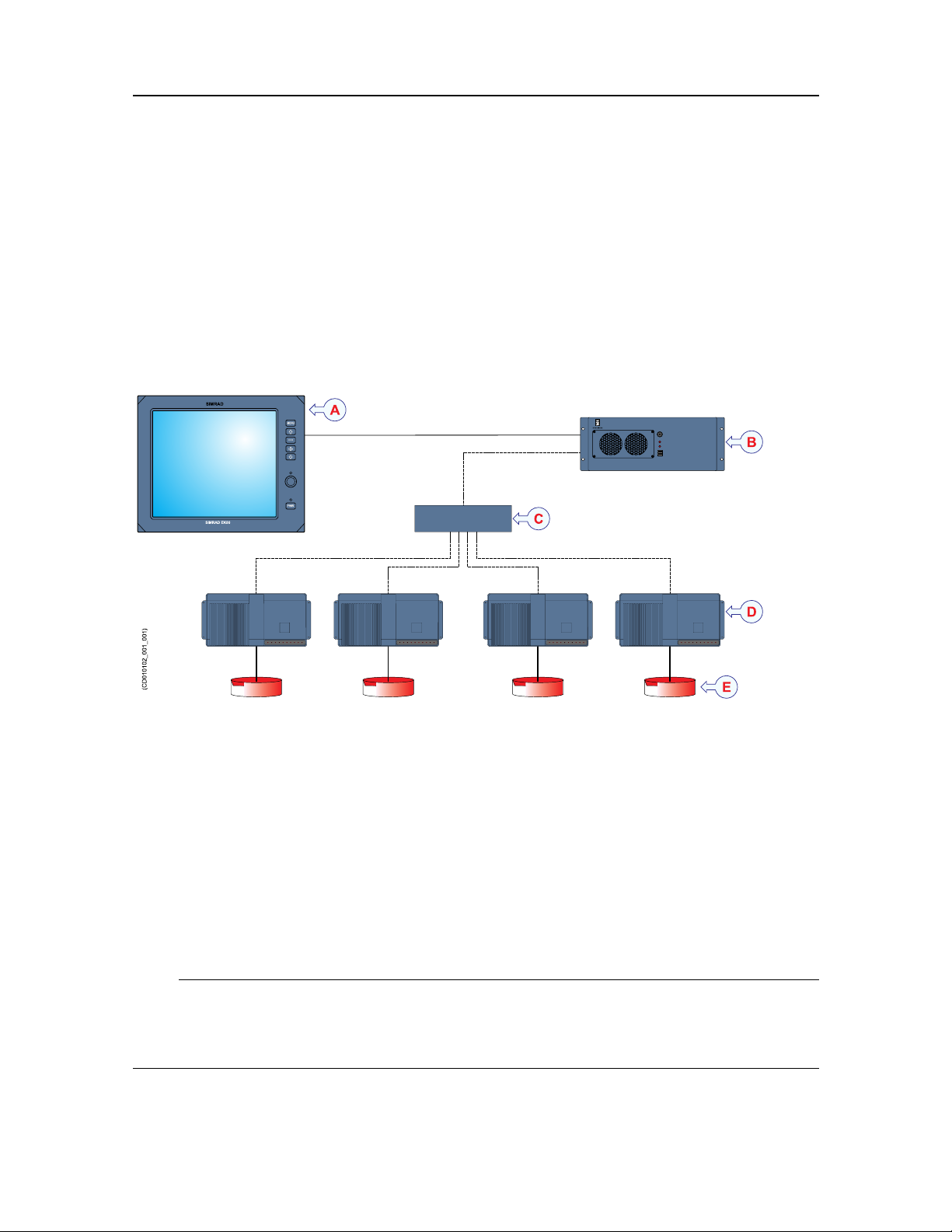
Systemdiagram
ThesystemdiagramidentiesthemaincomponentsofabasicEK80system,aswellasthe
connectionsbetweentheunits.Interfacecapabilitiesandpowercablesarenotshown.
ThebasicSimradEK80Widebandscienticechosounderconsistsofonetransducer,one
WideBandTransceiver(WBT)andoneProcessorUnit(computer).
Additionaltransceiversandtransducerscanbeaddedtomeetyouroperationaland
functionalrequirements.
ADisplay
BProcessorUnit
CEthernetswitch
DWideBandTransceiver(WBT)
ETransducer
Post-processingsoftwareapplicationsmaybeprovidedfromthirdpartysuppliers.See
ourwebsiteformoreinformation.
•http://www.simrad.com
Note
Unlessotherwisespeciedinacontract,thedisplayandtheEthernetswitcharenot
includedinthestandarddeliveryfromKongsbergMaritime.Thesearecommercialitems
thatcanbepurchasedlocally.
16
394149/C
Page 19

Relatedtopics
Systemdescription,page13
SimradEK80
394149/C
17
Page 20

SimradEK80
Mainsystemunits
Topics
Displaydescription,page18
ProcessorUnitdescription,page19
Ethernetswitch,page20
WideBandT ransceiver(WBT)description,page20
Transducers,page21
Displaydescription
AdisplayisarequiredpartoftheEK80Widebandscienticechosounder.Forbest
readability,thedisplaymustbelocatedsothatitisbestprotectedfromglare,andwiththe
correctheightandangle.
AnycommercialdisplaycanbeusedwiththeEK80Widebandscienticechosounder,
providedthatthedisplaymeetstheminimumrequirements.
Note
ThedisplayisnotastandardpartoftheEK80delivery.Thisisacommercialitemthat
canbepurchasedlocally.
Thechosendisplaymustbedesignedformaritimeuse,anditmustmeettheminimum
performancespecications.Youmustalsomakesurethatthechosendisplaysupportsthe
videoformatsprovidedbytheProcessorUnit.
Tip
TheProcessorUnitofferstwovideooutputs.Twodisplaysmaythereforebeusedtoseethe
EK80presentations.Youmayplacethetwodisplaysnexttoeachother .Youmayalsochoose
toplacetheseconddisplayatanotherlocationonthevessel.
Thepresentationontheseconddisplayiscontrolledusingtheoperatingsystemfeatureson
theProcessorUnit.
18
394149/C
Page 21

SimradEK80
Relatedtopics
Minimumtechnicalrequirementsfordisplay,page225
ProcessorUnitdescription
TheProcessorUnitisthecomputerthatcontrolstheEK80system.Itisavitalpartofthe
EK80Widebandscienticechosounder.Itcontainstheoperationalsoftware,andoffers
theuserinterfacethatallowsyoutocontroltheEK80.Italsocontrolstheinterfaceto
peripheraldevices.
Thecomputermustcomplytotherequirement
specicationsprovidedbyMicrosoftfortheiroperating
systems.Itmustalsoprovidethenecessaryinterface
facilities(seriallinesandEthernetconnections)that
yourEK80willneedtocommunicatewithperipheral
systems.Thecomputermustbedesignedforruggeduse,andtheconstructionmustbeable
towithstandthevibrationsandmovementsofavessel.Theoperatingsystemmustbe
MicrosoftWindows
®
7.
AhighqualityEthernetadapterisrequired.IfyouwishtoconnecttheProcessorUnittothe
ship’snetwork,youwillneedtwoEthernetadapters.
Inthispublication,thecomputerisreferredtoastheProcessorUnit.
TheProcessorUnitisnormallymountedonthebridgeorinascienticlaboratory.
Note
TheEthernetadaptercommunicatingwiththeWideBandTransceiver(WBT)mustoffer
aReceiveBuffersfunction.Thisparametermustbesettoitsmaximumvalueifmorethan
oneWideBandTransceiver(WBT)isused.
TheProcessorUnitisnotastandardpartoftheEK80delivery.Asuitablecomputermay
beprovidedwiththeEK80system.TheProcessorUnitisdesignedforruggeduse,and
customizedbyKongsbergMaritime.Exceptfromthefans,itcontainsnomovingparts.It
isbasedonacommercialdesign,butthesoftwareandhardwarehasbeenspeciedand
assembledbyKongsbergMaritimetosuittheEK80requirements.Itissetupwithall
necessarysoftware.Consultyourlocaldealeroragentformoreinformation.
Relatedtopics
Additionalrequireditems,page28
385609ProcessorUnitoutlinedimensions,page206
Minimumcomputerrequirements,page224
394149/C
19
Page 22
SimradEK80
Ethernetswitch
AhighcapacityEthernetswitchisakeycomponentoftheEK80system.
IfyouusemorethanoneWideBandTransceiver(WBT)inyourEK80system,youmustuse
anEthernetswitchtoconnecteachWideBandTransceiver(WBT)totheProcessorUnit.
TheEthernetswitchisbydefaultnotincludedintheEK80delivery,butthisisacommercial
itemthatcanbepurchasedlocally.
Note
Makesurethatyourselectedswitchhasalargebandwidthcapacity.Minimum1Gb
(1000BASE-T)isrequired.YoumustalsomakesurethatallEthernetcablesaretype
Cat5eorbetter .Aslowerswitch-orlowqualitycables–willdecreasetheoperational
performanceoftheEK80.
1000BASE-T(alsoknownasIEEE802.3ab)isastandardforgigabitEthernetover
copperwiring.Each1000BASE-Tnetworksegmentcanbeamaximumlengthof100
meters(330feet),andmustuseCategory5cableorbetter(includingCat5eandCat6).
Wikipedia,April2014
Relatedtopics
Additionalrequireditems,page28
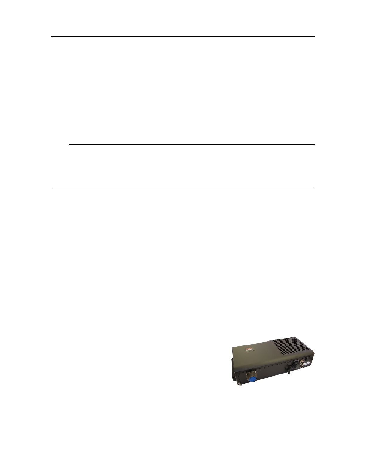
WideBandTransceiver(WBT)description
TheEK80WideBandTransceiver(WBT)isprovidedtotransmittheacousticenergyinto
thewater.Todothis,thetransceivercomputesandgeneratestheelectricsignalssentto
thetransducertoformatransmission-a'ping'.Aftereachtransmission,itwillreceive
theechoesfromthetargetsinthewatercolumnand/ortheseabed.Thesearelteredand
amplied,andthenconvertedtodigitalformat.
TheEK80WideBandTransceiver(WBT)comprises
aruggedboxprovidingallnecessarytransmitterand
receiverelectronics.
Thereceiverisdesignedforlownoise,anditcanhandle
inputsignalsspanningaverylargeinstantaneousdynamic
amplituderange.Alltargetsarecorrectlymeasuredand
displayed.
TheWideBandTransceiver(WBT)isdesignedforapplicationswhereperformanceisthe
toppriority.Ithasfour500Wchannelsthatcaneitherworkindependentlywithsinglebeam
transducers,ortogetherwithasplitbeamtransducer.
20
394149/C
Page 23

SimradEK80
Thetransceiveroperateswithinalargefrequencyband,andsupportssinglefrequencies,
frequencysweep(chirp)anduserdenedwaveforms.
Thedesignisoptimizedforapplicationswherepowerconsumptionandphysicalsizeisnot
critical,typicallyonboardavesseloraplatformwithpowerandcommunicationavailable
throughhighspeedEthernetcable.
AhighqualityEthernetcableconnectstheWideBandTransceiver(WBT)totheProcessor
Unit.ThedistancebetweentheProcessorUnitandthetransceivercanbeextendedupto
maximum70meters.Ifalongercableisrequired,cutitinhalf,andinsertanEthernet
switchtoprovidebufferamplication.
IfmorethanoneWideBandTransceiver(WBT)isused,asmallhighcapacityEthernet
switchisrequiredtoconnectthetransceiverstotheProcessorUnit.
TheEK80WBTrequiresanexternalpowersupplyoffering12to15Vdc,minimum5A.A
suitablepowersupplyisprovidedwiththedelivery.
Relatedtopics
Basicitemsprovidedwithastandarddelivery,page27
388697WideBandT ransceiver(WBT)outlinedimensions,page204
Transducers
TheEK80Widebandscienticechosoundercanbeusedwithalloursinglebeamand
splitbeamtransducers.
KongsbergMaritimecanprovidealargerangeofefcient
andaccurateSimradtransducersforsheryandshery
researchapplications.
Awiderangeofoperationalfrequenciesisavailable.
Simradtransducersaredesignedtoworkoptimallyacross
alargebandwidthandindemandingenvironments.For
scienticechosounders,wedividethefeaturesofthe
transducersintothreemaincategories;splitbeam,widebandanddepthrated.Several
transducerswilltmorethanonecategory.
FormoreinformationaboutthetransducersprovidedbyKongsbergMaritime,consult
theSimradwebsite.
•http://www.simrad.com
Theinstallationofthetransducer(ortransducers)isnotdescribedindetailinthismanual.
Pleaserefertothedocumentationprovidedwitheachtransducer.
394149/C
21
Page 24

SimradEK80
Relatedtopics
Splitbeamtransducers,page23
Widebandtransducers,page24
Depthratedtransducers,page25
Physicaldimensionsversusbeamopening,page26
22
394149/C
Page 25

SimradEK80
Splitbeam,widebandanddepthrated transducers
Simradtransducersaredesignedtoworkoptimallyacrossalargebandwidthandin
demandingenvironments.Forscienticechosounders,wedividethefeaturesofthe
transducersintothreemaincategories;splitbeam,widebandanddepthrated.Several
transducerswilltmorethanonecategory.
Topics
Splitbeamtransducers,page23
Widebandtransducers,page24
Depthratedtransducers,page25
Physicaldimensionsversusbeamopening,page26
Splitbeamtransducers
Asplitbeamtransducerisdesigntotransmittheacousticpulseusingonebeam,while
receivingtheechoesinthreeorfourindividualchannels.
Variationsinphaseofthereturnedechoesenableustolocatethetargetwithintheacoustic
beam.Onceyouknowthelocationofatargetyoucanmakeupforvariationsinthebeam
patterns,andintheendyoucanrecordcalibratedtargettrackswithintheacousticbeam.
Simradcommercializedthistechnologyinthe1980’s.Oursplitbeamechosoundersare
nowusedtorecorddataformarineresourcemanagementworldwide.
FormoreinformationaboutthesplitbeamtransducersprovidedbySimrad,consultour
website.
•http://www.simrad.com
ThefollowingsplitbeamtransducersarerecommendedfortheSimradEK80Wideband
scienticechosounder.
Model
ES18KSV-0886941811°
ES38-10KSV-2027143810°
ES38-7321842387°
ES70-7CKSV-203678707°
OrdernumberNominalfrequency
(kHz)
OpeningangleMaterial
Ceramic
Ceramic
Ceramic
Composite
394149/C
23
Page 26

SimradEK80
Model
ES120-7CKSV-2045801207°
ES200-7CKSV-2030032007°
ES333-7C3225983337°
OrdernumberNominalfrequency
(kHz)
OpeningangleMaterial
Composite
Composite
Composite
Theinstallationofthetransducer(ortransducers)isnotdescribedindetailinthismanual.
Pleaserefertothedocumentationprovidedwitheachtransducer.
Relatedtopics
Transducers,page21
Additionalrequireditems,page28
Widebandtransducers
Awidebandtransducercantransmitandreceiveonalargefrequencyrange,forexample45
to90kHz,85to170kHzor150to300kHz.Thismeansyouonlyneedthreetransducersto
covertheentirefrequencyrangefrom45to300kHz.
Inordertodesignatransducerthatiscapableofprovidingthisfrequencyrange,composite
technologyisourpreferredproductiontechnique.Allourwidebandtransducersare
producedusingcompositematerial.
Whenawidebandtransduceriscombinedwithawidebandtransceiveritispossibletomake
sweeptransmissions.Inthese,thetransmitfrequencycontinuouslyincreasesthroughoutthe
transmittedpulse.Thisfunctionalityisoftenreferredtoasa"chirp".
Itisalsopossibletotransmitonseveraldiscretefrequencies,oneatatime.
Ifyouareanadvanceduser,youcandeneanarbitrarysignal,suchasadolphin’sclick.
Thisopensupawholenewworldininterpretationoftheecho,takingagreatstepforward
towardsthegoalofprovidingaspeciesidenticationechosounder,or"ecosounder".
Formoreinformationaboutthewidebandtransducersprovided,consulttheSimradwebsite.
•http://www.simrad.com
ThefollowingwidebandtransducersarerecommendedfortheSimradEK80Wideband
scienticechosounder.Notethattheseareallsplitbeamtransducers.
Model
ES70-7CKSV-20367850-907°
ES120-7CKSV-20458085-1707°
ES200-7CKSV-203003160-3007°
ES333-7C322598250-5007°
OrdernumberFrequency(kHz)OpeningangleMaterial
Composite
Composite
Composite
Composite
24
394149/C
Page 27

SimradEK80
Theinstallationofthetransducer(ortransducers)isnotdescribedindetailinthismanual.
Pleaserefertothedocumentationprovidedwitheachtransducer.
Relatedtopics
Transducers,page21
Additionalrequireditems,page28
Depthratedtransducers
Sometimescollectingdatafromavesselsimplydoesnotdothejobforyou.Perhapsyou
needtoplacethetransducerindeeperwatersclosertothetargetforbetterresolution.Y ou
mustthenuseatransducerthatcanhandletheincreasedwaterpressure.
Ifitisnecessarytoplacethetransducerindeeperwaters,youcanuseatowedbody .You
canalsoplacethetransducerontheseabedforlongtermcollectionofdata.W ehavefor
manyyearsdesignedandbuilttransducersfordeepwaterapplicationslikethis.Ourseries
of7°depthratedtransducershavestandarddepthratingto1500meters.Wecanalsobuild
transducersforgreaterdepths.
Formoreinformationaboutthedepthratedtransducersprovided,consulttheSimrad
website.
•http://www.simrad.com
ThefollowingdepthratedtransducersarerecommendedfortheSimradEK80Wideband
scienticechosounder.Notethatallthesearealsosplitbeamtransducers.Standarddepth
ratingis1500meters.Ifyouneedtoworkonlargerdepths,feelfreetocontactusforadvice.
Model
ES38DDKSV-113392387°
ES70–7CD335039707°
ES70–18CD3216377018°
ES120-7CD3244101207°
ES200-7CDKSV–2071342007°
ES333-7CD3129023337°
OrdernumberNominalfrequency
(kHz)
OpeningangleMaterial
Ceramic
Composite
Composite
Composite
Composite
Composite
Theinstallationofthetransducer(ortransducers)isnotdescribedindetailinthismanual.
Pleaserefertothedocumentationprovidedwitheachtransducer.
Relatedtopics
Transducers,page21
Additionalrequireditems,page28
394149/C
25
Page 28

=
A
l
2b
( )
2
x
p
=
Nearfield
l
A
SimradEK80
Physicaldimensionsversusbeamopening
Thephysicaldimensionsofatransducercanbeexplainedasafunctionofthebeamopening
atagivenoperatingfrequency.
Traditionally,a7°openinganglehasbeenthestandardformarinesurveys.However,for
applicationswherethephysicalsizeandweightofthetransducerisimportant,youcan
reducethesizebyallowingalargeropeningangleoftheacousticbeam.
Theeffectivecircularareaofthetransducerfaceiscalculatedfromtheequation:
Where:
•A=effectivetransducercirculararea
•λ=wavelength
•ß=beamwidthinradians(-3dBpoints)
Thetransducerneareldistheregionrightinfrontofthetransducerface,wherethesound
wavesarecomplicatedanddoesnotfalloffsphericallywithrange.Targetswithinthenear
eldwillnotbedetectedcorrectly .Theneareldiscalculatedbytheequation:
Parametersfromtypicalscientictransducersaregiveninthetable.Themaximumand
minimumsourcelevel(SL)iscalculatedfromtheavailablepowersettingsontheSimrad
EK80scienticechosounder.
FrequencyWavelength
18kHz
38kHz
70kHz
120kHz
200kHz
333kHz
83mm11°
39mm7°
21mm7°
13mm7°
8mm7°
5mm
BeamwidthMax/MinSLEffective
225/215dB
229/219dB
227/217dB
222/212dB
220/212dB
7°
212/209dB
Neareld
circulararea
1479cm²178cm
820cm²208cm
242cm²113cm
82cm²66cm
30cm²39cm
11cm²24cm
Relatedtopics
Transducers,page21
26
394149/C
Page 29

SimradEK80
Scopeofsupply
Topics
Basicitemsprovidedwithastandarddelivery,page27
Additionalrequireditems,page28
Additionaloptionalitems,page30
Basicitemsprovidedwithastandarddelivery
ToassembleacompleteEK80system,youwillneedasetofsystemunits.Themainunits
requiredareprovidedwiththestandarddelivery .Otherrequiredunitsmaybepurchased
fromKongsbergMaritimeorobtainedlocally.Someunitsareoptional.
WhenyouunpackthepartsprovidedwiththeEK80delivery,verifythatthefollowing
itemsareincluded.
WideBandT ransceiver(WBT)
OneormoreWideBandTransceiver(WBT)unitsareprovided.
Product
WBT(10to30kHz)
WBT(25to50kHz)
WBT(45to90kHz)
WBT(85to170kHz)
WBT(150to300kHz)
WBT(250to500kHz)
Ordernumber
402578
402579
402580
402581
402582
402583
Inthebox
TransceiverUnit
Powersupplywithcables
USBwithsoftwareanddocumentation
Softwarelicense
Operationalsoftware
Operationalsoftwareisprovidedonasuitablemedia.
IftheProcessorUnitispurchasedfromKongsbergMaritime,theoperationalsoftwareis
installedontheProcessorUnit,andreadyforuse.
Enduserdocumentation
Enduserdocumentationisprovidedonpaperand/ordigitalformats.Alldocumentation
relatedtooperationandinstallationcanalsobedownloadedfromourwebsite.
•http://www.simrad.com/ek80
394149/C
27
Page 30

SimradEK80
Relatedtopics
WideBandT ransceiver(WBT)description,page20
388697WideBandT ransceiver(WBT)outlinedimensions,page204
Additionalrequireditems
AdditionalitemsareavailablefortheEK80.SomearerequiredforEK80operation.These
itemsmustbeaddedtotheEK80forfulloperationalfunctionality.
beprovidedbyKongsbergMaritime.YoucanorderthemalongwiththeotherbasicEK80
items.Youmayalsopurchasethemfromyourdealeroranotherlocalsupplier.
Computer
TheSimradEK80systemisdesignedtobecontrolledbyamaritimecomputer.This
computermustbebasedontheMicrosoftWindows
®
7operatingsystem.Thecomputer
mustbedesignedforruggeduse,andtheconstructionmustbeabletowithstandthe
vibrationsandmovementsofavessel.
Theadditionalitemscan
ThecomputermustcomplytotherequirementspecicationsprovidedbyMicrosoftfortheir
operatingsystems.Itmustalsoprovidethenecessaryinterfacefacilities(seriallinesand
Ethernetconnections)thatyourEK80willneedtocommunicatewithperipheralsystems.
AlaptopcomputercanbeusedifitmeetsthetechnicalrequirementsforEK80operation.
TheProcessorUnitisnotastandardpartoftheEK80delivery.Asuitablecomputermaybe
providedwiththeEK80system.Consultyourlocaldealeroragentformoreinformation.
Item
ProcessorUnit389845
Ordernumber
Inthebox
•Computer(Enix)
•Software
•Powercable
•Seriallineconnectorsandadapters
Transducer(s)
Alargerangeoftransducersisavailableforthedifferentoperationalfrequencies.For
ordernumbers,seeourwebsite.
•http://www.simrad.com
Display
ThedisplayisnotastandardpartoftheEK80delivery.Thisisacommercialitemthat
canbepurchasedlocally.
AnycommercialdisplaycanbeusedwiththeEK80Widebandscienticechosounder,
providedthatthedisplaymeetstheminimumrequirements.Thechosendisplaymustbe
28
394149/C
Page 31

SimradEK80
designedformaritimeuse,anditmustmeettheminimumperformancespecications.
Youmustalsomakesurethatthechosendisplaysupportsthevideoformatsprovidedby
theProcessorUnit.
Wesuggestthatyoupurchasealargehigh-resolutiondisplay.
KongsbergMaritimemayprovideasuitabledisplay.Consultyourlocaldealeroragentfor
moreinformation.
Item
Display335513
Mountinghardware339785
Ordernumber
Inthebox
•DisplayHattelandJH19T14(19-inch,
1280x1024)
•Powercable
•Documentation
Ethernetswitch
IfyouusemorethanoneWideBandTransceiver(WBT),anEthernetswitchisrequired.
ThisisusedtoconnecteachWideBandTransceiver(WBT)totheProcessorUnit.The
EthernetswitchisnotapartoftheEK80scopeofsupply.
KongsbergMaritimemayprovideasuitableEthernetswitch.Consultyourlocaldealeror
agentformoreinformation.
Item
Ethernetswitch352527
Ordernumber
Inthebox
•EthernetswitchBlackBox
LBS209AE-R2
•Powersupply
•Documentation
Relatedtopics
ProcessorUnitdescription,page19
Ethernetswitch,page20
Splitbeamtransducers,page23
Widebandtransducers,page24
Depthratedtransducers,page25
385609ProcessorUnitoutlinedimensions,page206
Minimumtechnicalrequirementsfordisplay,page225
Minimumcomputerrequirements,page224
394149/C
29
Page 32

SimradEK80
Additionaloptionalitems
AdditionalitemsareavailablefortheEK80.SomeareoptionalforEK80operation.These
mayforexamplesimplifytheinstallation,orincreasethefunctionality.Youcanorderthem
alongwiththeotherbasicEK80items.Youmayalsopurchasethemfromyourdealer
oranotherlocalsupplier.
WBTCabinetwithdrawers
TheWBTCabinetisacustomized19"-inchinstrumentrackttedwithpowerfulshock
absorbers.Thecabinetcancontainmaximumsevencustomdrawers,andeachofthesewill
holdoneWideBandTransceiver(WBT)anditspowersupply.AnEthernetswitchanda
powerdistributorpanelareincludedthebottomofthecabinet.
TheWBTCabinetisdeliveredwithsixdrawers.EachWBTDrawerwillholdoneWide
BandTransceiver(WBT).
TheWBTDrawerisdesignedtotintoanycommercial19-inchrack.
Item
WBTCabinet402244
WBTDrawer400791
Ordernumber
Inthebox
•19-inchrack(24U)
•WBTDrawers(6)
•Ethernetswitch
•Powerrail
•Shockabsorbers
•Mountinghardware
•WBTDrawer
•Mountinghardware
InstallationbracketforWBTPowersupply
Adedicatedinstallationbracketassemblymaybeorderedseparately.Thisbracketcanbe
usedtoinstalltheWBTPowersupplyonabulkheadorthesidewallinsideacabinet.
Item
InstallationbracketforWBT
Powersupply
Ordernumber
393510
Inthebox
•Installationbracket
•Mountinghardware
Secondarydisplay
TheProcessorUnitofferstwovideooutputs.Twodisplaysmaythereforebeusedtosee
theEK80presentations.ThedisplayisnotastandardpartoftheEK80delivery.Thisisa
commercialitemthatcanbepurchasedlocally.
30
394149/C
Page 33

SimradEK80
Youmayplacethetwodisplaysnexttoeachother.Youmayalsochoosetoplacethe
seconddisplayatanotherlocationonthevessel.Thepresentationontheseconddisplayis
controlledusingtheoperatingsystemfeaturesontheProcessorUnit.
AnycommercialdisplaycanbeusedwiththeEK80Widebandscienticechosounder,
providedthatthedisplaymeetstheminimumrequirements.Thechosendisplaymustbe
designedformaritimeuse,anditmustmeettheminimumperformancespecications.
Youmustalsomakesurethatthechosendisplaysupportsthevideoformatsprovidedby
theProcessorUnit.
Tip
IfyoualsowishtocontroltheEK80fromthissecondarydisplaylocation,youcanadd
anextraOperatingPanel.
KongsbergMaritimemayprovideasuitabledisplay.Consultyourlocaldealeroragentfor
moreinformation.
Item
Display335513
Mountinghardware339785
Ordernumber
Inthebox
•DisplayHattelandJH19T14(19-inch,
1280x1024)
•Powercable
•Documentation
UninterruptiblePowerSupply(UPS)
ItisimportanttoensurecontinuousoperationoftheEK80independentofvaryingquality
ofthevessel'smainssupply.Theuseofanuninterruptiblepowersupplyistherefore
recommended.
UninterruptiblepowersupplyunitsarenotincludedinthestandardEK80delivery.These
itemsmustbepurchasedlocally.
Severalcommercialtypesareavailable.TochoosethebestpowersolutionforyourEK80
installation,considerenvironmentalconditions,spaceavailable,theavailabilityandduration
ofthebatteries,andthepowerrequirementsoftheEK80.
Theminimumspecicationsfortheuninterruptiblepowersupplyare:
•Inputvoltage:Theinputvoltagemusttvesselsupplyvoltage
•Outputvoltage:230V AC,50Hz
•Outputpower:TheoutputpowermustexceedtherequirementsoftheEK80
•Outputform:TheoutputACvoltagemustbeasinewave
394149/C
31
Page 34

SimradEK80
Relatedtopics
400930WBTCabinetoutlinedimensions,page210
32
394149/C
Page 35

SimradEK80
Generalsafetyrules
Thefollowingsafetyprecautionsmustbefollowedatalltimesduringinstallationand
maintenancework.
WARNING
Theequipmentoperateson230Vac50/60Hz.Thisvoltageislethal!Youmustnever
workaloneonhigh-voltageequipment!
•Youmustalwaysswitchoffallpowerbeforeinstallationormaintenanceworkonthe
EK80system.
Usethemaincircuitbreaker,andlabelthebreakerwithawarningsignthatinforms
othersthatmaintenanceorinstallationworkisinprogressonthesystem.
•Forsafetyreasons,twopersonsmustalwaysbepresentduringtroubleshootingwith
powerON.
•Readandunderstandtheapplicablerstaidinstructionsrelatedtoelectricshock.
•Whenevermaintenanceisinprogress,itisessentialthatarstaidkitisavailable,and
thatallpersonnelarefamiliarwiththerstaidinstructionsforelectricalshock.
394149/C
33
Page 36

SimradEK80
Installationrequirements
Topics
Supplypowerrequirements,page34
UninterruptiblePowerSupply(UPS)requirements,page34
Cablesandwiringrequirements,page35
Compassdeviationrequirements,page35
Noisesources,page35
Drydockingrequirements,page36
Requirementforclassicationapproval,page36
Supplypowerrequirements
Observethegeneralrequirementsrelatedtothesupplypower.
ThesupplyvoltagetotheEK80mustbekeptwithin±10%oftheinstallation’snominal
voltage.
Maximumtransientvoltagevariationsonthemainswitchboard’sbus-barsarenottoexceed
-15%to+20%ofthenominalvoltage(exceptunderfaultconditions).
UninterruptiblePowerSupply(UPS)requirements
ObservetheserequirementsrelatedtotheUninterruptiblePowerSupply(UPS).
WerecommendthattheEK80systemispoweredusinganUninterruptiblePowerSupply
(UPS)withsinewaveoutput.
TheUninterruptiblePowerSupply(UPS)musthavethecapacitytoindependentlymaintain
powertotheEK80foraminimumof10minutes.
ThisensuresthattheEK80canbeswitchedoffinacontrolledmannerintheeventofa
powerfailure.
34
394149/C
Page 37

SimradEK80
Cablesandwiringrequirements
CorrectwiringiscrucialfortheoperationalperformanceoftheEK80.
Allcablesrunningbetweensystemcabinetslocatedindifferentroomsand/orondifferent
decksmustbesupportedandprotectedalongtheirentirelengthsusingconduitsand/orcable
trays.Notethatthecablesmustnotbeinstalledinthevicinityofhigh-powersuppliesand
cables,antennacablesorotherpossiblesourcesofinterference.
Alltransducercablesmustberuninsteelconduits.
Formoredetailedinformationaboutcablesandwiring,refertothebasiccablerequirements.
Compassdeviationrequirements
EK80unitsthatareinstalledonthebridgemayhaveaneffectonthecompass.
Oncetheinstallationiscomplete,thevesselmustbeswungwiththeEK80inbothoperative
andinoperativemodes.
Theshipownerandcaptainareresponsibleforupdatingthecompassdeviationtable
accordinglywithregardtothevessel’snationalregistryandcorrespondingmaritime
authority.
Noisesources
TheoperationalperformanceoftheEK80Widebandscienticechosounderdependsonthe
noiseconditions.Itisessentialthatthenoisesignatureisaslowaspossible.
Thevessel’shull,rudder(s)andpropeller(s)mustbethoroughlyinspectedindrydock
priortoinstallation.
Roughnessbelowthewater-linedeformitiesintheshellplatingandprotrudingobstacles
cancreateunderwaternoise.Thesesourcesofturbulencemustbesmoothedorremoved
asbestaspossible.
Note
Itisespeciallyimportantthatthepropeller(s)arenotpittedordamaged.
394149/C
35
Page 38

SimradEK80
Drydockingrequirements
Wheneveroneormoretransducersaremountedunderthevessel’shull,special
considerationsmustbemadepriortodrydocking.
Makesurethatampleclearanceisprovidedunderthetransducersand/orblisterwhenyou
areplacingthevesselindrydock.
Donotplacesupportingblocksorstructuresinthevicinityofthetransducers.
Thelocationofeachtransducermustbenotedonthevessel’sdockingplanforfuture
reference.
Priortodrydocking,powerdowntheEK80.Disengagethecircuitbreakerifnecessary.
LabeltheProcessorUnitand/orthecircuitbreakerclearlytopreventanyonefrompowering
uptheEK80accidentally .
Requirementforclassicationapproval
ClassicationapprovalisrequiredfortheEK80installation.
TheEK80transducerinstallationmustbeapprovedbyDNVGLoranothernational
classicationsociety.
Theshipownerandshipyardperformingtheinstallationareresponsibleforobtainingthe
classicationapproval.
36
394149/C
Page 39

Networksecurity
IfaEK80systemisconnectedtotheship’slocalareanetwork,datasecurityisofvital
importance.
EquipmentmanufacturedbyKongsbergMaritimearefrequentlyconnectedtotheship's
localareanetwork(LAN).Connectinganycomputertoanetworkwillalwaysexpose
thedataonthatcomputertoallothercomputersconnectedtothesamenetwork.Several
threatsmayimmediatelyoccur:
•Remotecomputerscanreadthedata.
•Remotecomputerscanchangethedata.
•Remotecomputerscanchangethebehaviourofthecomputer,forexamplebyinstalling
unwantedsoftware.
Usually,twoparametersareusedtodenethethreatlevel:
1Thelikelihoodthatanyremoteconnectionwilldoanyoftheabove.
SimradEK80
2Thedamagedoneifaremoteconnectionsucceedsdoingthis.
BecauseKongsbergMaritimehasnoinformationregardingthecompletesysteminstallation
onanyvessel,wecannotestimatethethreatlevelandtheneedfornetworksecurity.For
thisreason,wecannotacceptresponsibilityfornetworksecurity.Systemsprovidedby
KongsbergMaritimeareregardedasstand-aloneofinesystems,eventhoughtheymaybe
connectedtoanetworkforsensorinterfacesand/ordatadistribution.
Note
NonetworksafetyapplicationsareinstalledonanyKongsbergMaritimecomputers.The
computersarethusnotprotectedagainstviruses,malwareorunintentionalaccessfrom
externalusers.
SecuringtheEK80systemitselfhasnomeaningunlessthereisapolicyinplacethatsecures
allcomputersinthenetwork.Thispolicymustincludephysicalaccessbytrainedandtrusted
users.Thecustomer/enduseroftheEK80systemwillalwaysbeinchargeofdeningand
implementingasecuritypolicy,andprovidingtherelevantnetworksecurityapplications.
Note
KongsbergMaritimewillnotacceptanyresponsibilityforerrorsand/ordamagescausedby
unauthorizeduseoraccesstotheEK80.
394149/C
37
Page 40

SimradEK80
Relatedtopics
Important,page12
Supportinformation
IfyouneedtechnicalsupportforyourSimradEK80youmustcontactyourlocaldealer,
oroneofoursupportdepartments.Alistofallourofcesanddealersisprovidedonour
website.Y oucanalsocontactourmainsupportofceinNorway .
Norway(Mainofce)
•Companyname:KongsbergMaritimeAS/Simrad
•Address:Strandpromenaden50,3190Horten,Norway
•Telephone:+4733034000
•Telefax:+4733042987
•Website:http://www.simrad.no
•E-mailaddress:simrad.support@simrad.com
Spain
•Companyname:SimradSpain
•Address:PoligonoPartidaTorres38,03570Villajoyosa,Spain
•Telephone:+34966810149
•Telefax:+34966852304
•Website:http://www.simrad.es
•E-mailaddress:simrad.spain@simrad.com
France
•Companyname:SimradFrance
•Address:5ruedeMenMeur,29730Guilvinec,France
•Telephone:+33298582388
•Telefax:+33298582388
•Website:http://www.simrad.fr
•E-mailaddress:simrad.france@simrad.com
38
394149/C
Page 41

SimradEK80
USA
•Companyname:KongsbergUnderwaterT echnologyInc/SimradFisheries
•Address:1921033rdAveW ,Lynnwood,W A98036,USA
•Telephone:+14257121136
•Telefax:+14257121193
•Website:http://www.simrad.com
•E-mailaddress:sh.usa.support@simrad.com
Malaysia
•Companyname:KongsbergMaritimeMalaysiaSdn.Bhd
•Address:Unit27-5SignatureOfces,TheBoulevard,MidV alleyCity,LingkaranSyed
Putra,59200KualaLumpur,Malaysia
•Telephone:+6564117488
•Telefax:+60322013359
•Website:http://www.simrad.com
•E-mailaddress:simrad.asia@simrad.com
Korea
•Companyname:KongsbergMaritimeKoreaLtd
•Address:#1101-HarborTower,113-1,Nampodong6-Ga,Jung-Gu,Busan600-046Korea
•Telephone:+82-51-242-9933
•Telefax:+82-51-242-9934
•Website:http://www.simrad.com
•E-mailaddress:simrad.korea@simrad.com
Relatedtopics
Important,page12
394149/C
39
Page 42

SimradEK80
Preparations
Topics
Installationsummary,page41
Aboutinstallationdrawings,page42
Tools,equipmentandconsumablesrequiredforEK80installation,page43
Personnelqualications,page44
Wheretoinstallthetransducer,page45
Acousticnoise,page48
40
394149/C
Page 43

Preparations
Installationsummary
InstallationoftheEK80isademandingtaskthatrequirescarefulpreparations,anumberof
specicprocedures,wiringandrequiredsystemsettings.
Context
Anoverallinstallationprocedureisprovidedbelow.Theproceduredoesnotdescribeany
detailedtasks,butreferstotherelevantproceduresinthismanual.
Note
InordertoobtainmaximumsafetyandEK80performance,itisveryimportantthatthe
installationproceduresinthismanualarecompliedto.Youmustdothetasksintheorder
theyaredescribed.Thevesselownermustmakesurethattheinstallationshipyardholds
theapplicablecompetencetoperformtheinstallation,andthattheapplicablemaritime
authoritiesareavailabletoverifyandcertifytheinstallation.
Procedure
1Basedonthevesseldrawingsandbestpractice,determinewherethetransducer(or
transducers)shallbelocated.
Necessaryconsiderationsmustbetakentoavoidacousticandelectricdisturbances.
Note
Thisinformationinthisdocumentmustberegardedasgeneralguidelinesand
recommendationsonly.
Theinstallationshipyardmustdesignandmanufactureinstallationhardwaretotthe
transducertoeachindividualvessel.Wheneverrequired,theinstallationshipyardmust
alsohavethetransducerinstallationapprovedbytheapplicablemaritimeauthorities.
2Installeachtransducer.
Theinstallationshipyardmustprovideallnecessarydrawingsinordertodothis
installation,andifrequired,thesedrawingsmustbeapprovedbytheapplicable
maritimeauthorities.Eachtransducerwillpenetratethehull,andthisisthereforea
crucialpartoftheEK80installation.
Relevantinstallationdrawingsareincludedwitheachtransducer.Drawingscanalsobe
downloadedfromourwebsite:
•http://www.simrad.com
394149/C
41
Page 44

SimradEK80
3InstalltheEK80systemunits.
NotethatsomeEK80systemunitsmaybecommercial.Unlessorderedspecically
thesearenotincludedinthedelivery,andmustbepurchasedlocally.
4InstallthecablesbetweentheEK80systemunits.
Observetherelevantcableplan,procedures,aswellasthegeneralrequirementsfor
cabling.
5PoweruptheEK80forthersttime,andsetittowork.
Note
InordertosetuptheEK80inasafeandcorrectmanner ,theseproceduresmustbe
compliedto!
6Connecttheperipheralunits.
7Runacompletesystemtest.
ThetestsaredescribedinSettingtoworkchapterinthismanual,aswellasinthe
HarbourAcceptanceTestandtheSeaAcceptanceTestdocuments.
Furtherrequirements
FillinandsigntheInstallationRemarksform,andsendittoSimrad'ssupportdepartment
asspeciedontheform.
Aboutinstallationdrawings
Theinstallationshipyardmustprovideallnecessarydesignandinstallationdrawings,as
wellastherelevantworkstandardsandmountingprocedures.
Note
Ifrequired,alldocumentsprovidedbytheshipyardforthephysicalinstallationoftheEK80
mustbeapprovedbythevessel’ snationalregistryandcorrespondingmaritimeauthority
and/orclassicationsociety.Suchapprovalmustbeobtainedbeforetheinstallationcan
begin.Theshipownerandshipyarddoingtheinstallationareresponsibleforobtainingand
payingforsuchapproval.
KongsbergMaritimeoffersfreeadviceforinstallationplanning.Proposedarrangements
maybesentforcommentaryorsuggestions.Thefollowingdrawingsshouldbesubmitted
shouldassistanceberequested:
42
394149/C
Page 45

Preparations
•Generalarrangement
•Bodyplananddrawingsoftherelevantcompartment
•Linesplan
Relevantoutlinedimensionsandproductiondrawingscanbedownloadfromourwebsite.
MostdocumentsareavailableinPDFand/orAutoCad(DWG)formats.
•http://www.simrad.com/ek80
Tools,equipmentandconsumablesrequired forEK80installation
Tools,equipmentandconsumablesrequiredforEK80installation
InordertodotheEK80installation,allnecessarytoolsandequipmentformechanicalhull
work,cabinetinstallationandelectricalwiringmustbeavailable.Itisnotpracticalto
provideadetailedlistofallnecessarytoolsandequipment.However,youmustmakesure
thatthefollowingspecializedtoolsareavailable.
•Allnecessarytoolsandconsumablesrequiredforwelding
•Allnecessarytoolsandconsumablesrequiredforphysicalinstallationofunits,cabinets
andracks
•Allnecessarytoolsandconsumablesrequiredforelectricalinstallations
Note
Wheneverspecicconsumablesorspecialtoolsortestinstrumentsarerequired,these
areidentiedintherelevantprocedure(s).
394149/C
43
Page 46

SimradEK80
Personnelqualications
TheinstallationoftheEK80isademandingtask.Itisveryimportantthatthepersonnel
involvedintheinstallationtasksarecompetentandexperiencedcraftsmen.
Asaminimum,thefollowingcertiedcraftsmenmustbeavailable:
•navalarchitects
•welders
•electricians
•projectmanager
Note
Thequalityoftheweldingiscriticaltothesafetyofthevessel.Weldingmustonlybedone
byacertiedwelder .
Thenalinstallationweldsmustbeapprovedbythevessel’ snationalregistry,the
correspondingmaritimeauthorityand/orclassicationsociety.Observetherelevantrules
andregulationsrelatedtowelding.
44
394149/C
Page 47

Wheretoinstallthetransducer
Topics
Introduction,page45
Mountthetransducerdeep,page45
Avoidprotrudingobjects,page46
Stayfarawayfromthepropellers,page46
Chooseapositionfarawayfromthebowthruster(s),page47
Summaryandgeneralrecommendations,page47
Preparations
Introduction
Asingleanswertothequestion“wheretoinstallthetransducer”cannotbegiven.
Thephysicallocationofthetransducerdependsonthevessel'sdesignandconstruction,how
thehullisshaped,andhowthewaterrunsalongthehull.Therearehoweveranumberof
importantguidelines,andsomeoftheseareevenconicting.
Note
Theinformationheremustbeconsideredasgeneraladvice.EachEK80installationmustbe
handledseparatelydependingonthehulldesign.
Mountthetransducerdeep
InordertoachievethebestpossibleEK80performance,mountthetransducerasdeepas
possibleunderthevessel’shull.
Considerthesituationswhenthevesselisunloaded,andwhenitispitchinginheavyseas.
Thereareseveralreasonsforthis.
1Theupperwaterlayersoftheseacontainamyriadofsmallairbubblescreatedby
thebreakingwaves.
Inheavyseastheupper5to10metresmaybelledwithair,andthehighest
concentrationswillbenearthesurface.Airbubblesabsorbandreectthesound
energy,andtheymayinworstcasesblockthesoundtransmissionaltogether.
394149/C
45
Page 48

SimradEK80
2Anotherreasontogodeepiscavitation.
Cavitationistheformationofsmallbubblesinthewaterclosetothetransducerface
duetotheresultinglocalpressurebecomingnegativeduringpartsoftheacoustic
pressurecycles.Thecavitationthresholdincreaseswiththehydrostaticpressure.
3Thetransducermustneverbeliftedfreeofthewatersurface.
Transmittingintoopenairmaydamagetheitbeyondrepair.Mountingthetransducer
atadeeppositiononthehullwillinmostcasespreventthis.
4Ifthetransducerisliftedupfromthewaterduringheavyseas,itmaybedamagedwhen
thehullstrikesbackattheseasurface.
Thisisespeciallyimportantforlowfrequencytransducerswithlargefaces.
Avoidprotrudingobjects
Objectsprotrudingfromthehullwillgenerateturbulenceandownoise.Thiswillreduce
theEK80performance.
Suchobjectsmaybezincanodes,sonartransducersoreventhevessel'skeel.Holesand
pipeoutletsarealsoimportantnoisesources,aswellasroughsurfacescausedbybad
welding.Alltheseprotrudingobjectsmayactasresonantcavitiesamplifyingtheow
noiseatcertainfrequencies.
Donotplaceatransducerinthevicinityofsuchobjects,andespeciallynotclosebehind
them.Forthesamereason,itisveryimportantthatthehullareaaroundthetransducerface
isassmoothandlevelaspossible.
Eventracesofsealingcompound,sharpedges,protrudingboltsorboltholeswithoutlling
compoundwillcreatenoise.
Stayfarawayfromthepropellers
Thepropulsionpropellersisthedominantnoisesourceonmostvessels.Thenoiseis
transmittedthroughtheseawater,andmayoftenreducetheperformanceofyourEK80
system.
Forthisreason,thetransducermustbeplacedfarawayfromthepropellers,whichmeans
ontheforepartofthehull.Positionsoutsidethedirectlineofsightfromthepropellers
arefavourable.
Onsmallvesselswithshortdistancesitisadvisedtomountthetransduceronthatside
ofthekeelwherethepropellerbladesmoveupwards,becausethepropellercavitationis
strongestontheotherside.Thecavitationstartsmosteasilywhenthewaterowsinthe
samedirectionasthepropellerblade,andthatistosomedegreethecaseatthatsideofthe
keelwherethepropellerbladesmovedownwards.
46
394149/C
Page 49

Preparations
Chooseapositionfarawayfromthebowthruster(s)
Bowthrusterpropellersareextremelynoisy.
Wheninoperation,thenoiseandcavitationbubblescreatedbythethrustermaymakeyour
EK80Widebandscienticechosounderuseless,almostnomatterwherethetransduceris
installed.
Andwhennotinoperation,thetunnelcreatesturbulence.Ifyourvesselispitching,the
tunnelmaybelledwithairoraeratedwaterintheupperpositionandreleasethisinthe
lowerposition.
Ingeneral,alltransducersshouldthereforebeplacedwellawayfromthebowthruster(s).In
mostcases,alocationforwardofthebowthrusterisadvantageous.
However,thisisnotaninvariablerule.Certainthrusterdesignscombinedwiththeirphysical
locationsonthehullmaystilloffersuitablelocationsnearthethruster.Ifyouareindoubt,
consultanavalarchitect.
Summaryandgeneralrecommendations
Someoftheinstallationguidelinesprovidedfortransducersmaybeconicting.Forthis
reason,eachvesselmustbetreatedindividuallyinordertondthebestcompromise.
Ingeneral,themostimportantfactoristoavoidairbubblesinfrontofthetransducerface.
Forthisreason,therecommendedtransducerlocationisnormallyintheforepartofthehull,
wellaheadofthenoisecreatedbythebowwave.Themaximumdistancefromthebowis
normallyequaltoonethirdofthetotalwaterlinelengthofthehull.
Ifthevesselhullhasabulbousbow,thismaywellbeagoodtransducerlocation,butalso
inthiscasetheowpatternoftheaeratedwatermustbetakenintoconsideration.Often
theforemostpartofthebulbispreferable.
Thisappliestothevesselinnormaltrimandspeed.
Important
Undernocircumstancesshouldthetransducerbetiltedbackwardswhenthevesselismoving
atanappreciablespeed.Mountingscrewsmustneverbeextrudingfromthetransducer,and
thespacearoundthescrewsmustbelledwithacompoundoralockingring.
394149/C
47
Page 50

SimradEK80
Acousticnoise
Aswithanyotherhydroacousticsystems,thequalityoftheEK80presentationsaresubject
tounwantedacousticnoise.Theechoesfromanylargeandsmalltargetmustbedetected
insidethenoise.
Itisimportantthatwekeepthisnoiselevelaslowaspossibleinordertoobtainlongrange
anddependableinterpretationsoftheechoes.Evenwiththeadvancednoiselteringoffered
bytheEK80,wemustaddressthenoisechallengeduringbothplanningandpreparations
fortheEK80installation.
Topics
Contributingfactors,page48
Selfnoise,page50
Ambientnoise,page52
Fishinggearnoise,page53
Electricalnoise,page53
Somemeanstoreduceacousticnoise,page53
Contributingfactors
Severalfactorsarecontributingtotheperformanceofthehydroacousticequipmentused
onboardavessel.
Suchfactorsinclude:
•Thequalityandpropertiesofthetransmittedsignal
•Thequalityofthereceivingsystem
•Theoperationalsettingsmadeduringoperation
•Thepropertiesofthetarget(s)
•Thesignal-to-noiseratio
Themajorityofthesefactorscanneitherbecontrollednorimprovedbymeansofinstallation
methodsortransducerlocations.Thequalityandpropertiesofthetransmittingandreceiving
systemsarekeyfactorsduringourproductdevelopment,whileourenduserdocumentation
aimstohelptheusertomaketherightltersettingsduringoperation.Asforthetarget
properties,thereisnothinganyofuscandowiththose.
Thesignal-to-noiseratio,however,canbeimprovedbymakingthecorrectchoicesduring
installation.
48
394149/C
Page 51

(CD019401_004_001)
Preparations
Signal-to-noiseratio(oftenabbreviatedSNRorS/N)isameasureusedinscienceand
engineeringthatcomparesthelevelofadesiredsignaltothelevelofbackgroundnoise.
Itisdenedastheratioofsignalpowertothenoisepower,oftenexpressedindecibels.
Aratiohigherthan1:1(greaterthan0dB)indicatesmoresignalthannoise.WhileSNR
iscommonlyquotedforelectricalsignals,itcanbeappliedtoanyformofsignal[...].
http://en.wikipedia.org/wiki/Signal_to_noise_ratio(September2013)
Foractivesonarandechosoundersystems,thesignalistheechothatwewanttoknow
somethingabout,whilethenoiseisanyunwantedsignalsordisturbances.Theechomustbe
detectedinthenoiseandthereforeitisnecessarytokeepthenoiselevelisaslowaspossible
inordertoobtainlongrangeanddependableinterpretation.Thenoisethatcontributesto
thesignaltonoiseratioonhydroacousticinstrumentsmaybedividedintothefollowing
typesofnoise:
•Selfnoise
•Ambientnoise
•Fishinggearnoise
•Electricalnoise
•Reverberation
AThetransducercanpickupnoisefrom
•Biologicaldisturbances
•Interference
•Cavitation
•Propellernoise
•Flownoise
•Acousticnoisefromotherhydroacousticsystems
BThetransducercableislong,andmaypickupelectricnoisefromgenerators,pumps,
coolingsystemsetc.
394149/C
49
Page 52

SimradEK80
CThepreampliersareverysensitive,andtheycaneasilypickupelectricalnoisefrom
internalandexternalpowersupplies.Theyarealsovulnerableforanaloguenoise
createdbytheirowncircuitry.Digitalnoisecreatedbytheconverterandprocessing
circuitrycanalsocreateproblems.
DA/Dconverterstransformtheanalogueechoestodigitalformat.
ESignalprocessingcircuitrycancreatedigitalnoise.
Selfnoise
Anyvesselequippedwithahydroacousticsystemwillproducemoreorlessselfnoise.
Therearemanysourcesofsuchselfnoise.
•Machinerynoise:Mainengine,auxiliaryengines,gears,pumps,blowers,refrigerator
systems,etc.
•Electricnoise:Electricmotors,groundloops,etc
•Propellernoise:Propellerbladeproperties,cavitation,shaftvibrations,staticdischarges
•Cavitation
•Flownoise:Laminarow,turbulentow,bubbles,etc
•Rattlenoise:Looseparts
•Interferences:Otherhydroacousticsystemsonyourownvessel
Wewillheregointosomedetailsinordertoanalysethedifferentsourcesofselfnoiseona
vesselandhowtheymayinuenceuponthenoiselevelofthehydroacousticinstruments.
Machinerynoise
Themaincontributorisusuallythemainengineonboardthevessel.Thecontributionfrom
auxiliarymachinerymay,however,beconsiderable,especiallyifsomeofitisinpoorshape.
Themachinerynoisecanbetransmittedtothetransducerasa:
•Structure-bornenoisethroughtheshipstructureandthetransducermountings
•Water-bornenoisethroughthehullintothewatertothetransducer
Electricnoise
Modernvesselsarenormallyequippedwithalotofelectricinstrumentssuchas
hydroacousticsystems,radars,navigationsystems,andcommunicationequipment.Any
electricinstrumentsmayinsomecauseelectricalinterferenceandnoise.
Internationalregulationsandcerticationsareusedtocontrolandreducethis,buteventhese
arelimitediftheelectricalsystemsarepoorlyinstalledandmaintained.
50
394149/C
Page 53

Preparations
Propellernoise
Thissourceisoftenthemainsourceofnoiseathighervesselspeeds.V ariablepitch
propellersorfastmovingpropellersusuallymakemorenoisethanxedpropellersorslow
movingpropellers.
Thisnoiseisusuallywater-borne.Insomecases,however,shaftvibrationsorvibrationsin
thehullnearthepropellermaybestructure-bornetothetransducer.Ifapropellerbladeis
damaged,thismayincreasethenoiseconsiderably.
Propellercavitationisaseveresourceofnoise."Singing"propellersmightbeasourceof
noise,whichinterferesatdiscretefrequencies.Insomecasesstaticdischargefromthe
rotatingpropellershaftmaybequitedisturbing.
Cavitation
Cavitationusuallyoccursmorewillingly
inairlledwaterandtheoccurrenceis
dependentonthehydrostaticpressure.
Cavitationisaseveresourceofnoise.
Thenoiseismadewhenthevoids
implode.Cavitationnoiseoftenoccursat
thepropellerandnearextrudingobjects
athigherspeeds.
Contributionstotheownoisemay
alsobecausedbyairbubbleshittingthe
transducerface,orbythesplashcaused
bythewavessetupbythevessel.In
somecasesaresonantphenomenonissetupinaholenearthehull.Thissoundwillhavea
discretefrequency,whileallotherownoisewillhaveawidefrequencyspectrum.
(ImagefromU.S.Navyinthepublicdomain.)
Flownoise
Everyobjectthatmovesthroughwaterwilldisturbthemedium,anditwillcausefrictionin
thewater.Thefrictionzoneiscalledtheowboundarylayer.Theowinthisboundary
layermaybelaminarorturbulent.
•Thelaminarowisanicelyordered,parallelmovementofthewater.
•Theturbulentowisadisorderlyowpattern,fullofeddies.
394149/C
51
Page 54

(CD010203_300_010)
SimradEK80
ATurbulentow
BLaminarow
CAirbubbles
Theboundarylayerincreasesinthicknesswhenitbecomesturbulent.Theboundarylayer
isthinintheforwardpartofthevesselhull,andincreasesasitmovesaft.Thethickness
dependsonshipsspeedandontheroughnessofthehull.Allobjectsstickingoutfrom
thehull,ordentsinthehull,willdisturbtheowandwillincreasethethicknessofthe
boundarylayer.Whentheowspeedishigh,theturbulencecanbeviolentenoughto
destroytheintegrityofthewater.Smallvoidsorcavitiesinthewaterwilloccurandthis
iscalledcavitation.
Rattlenoises
Rattlenoisemaybecausedbylooseobjectsinthevicinityofthetransducer,likexing
bolts.Therattlemayalsocomefromlooseobjectsinsidethehull.
Interference
Interferencefromotherhydroacousticequipmentonboardthesamevesselmaybean
annoyingsourceofdisturbance.Unlessthesamefrequencyisusedformorethanonepiece
ofequipmentonlythetransmittedpulsewillcontributetotheinterference.
Ambientnoise
Ambientnoiseisusuallynotalimitingfactortotheperformanceofsonarsandecho
sounders.
Theambientnoisemaybesplitupasfollows:
•Seanoise:Airbubbles,seismicdisturbances,waves,boundaryturbulence,etc.
•Biologicalnoise:Fish,mammals,etc.
•Manmadenoise:Othervessels,interference
52
394149/C
Page 55

•Precipitationnoise
Insomeareas,wheremanyvesselsareoperatingtogethertheengineandpropellernoise
fromothervesselsmightbedisturbing.
Interferencefromhydroacousticinstrumentslocatedinothervesselsmayalsobealimiting
factor.
Theseanoiseisascanbeexpecteddependentontheweatherconditions.Inbadweather
theseanoisecanbequitehigh.
Fishinggearnoise
Wheneveryourshinggearisinuse,itwillcreatenoise.
Abottomtrawl,forinstance,isaconsiderablenoisemaker.
Still,thisnoisewillseldombealimitingfactorforhullmountedsonarsorechosounders.
Preparations
However,foroperationofacatchmonitoringsystemoratrawlsonar,withthetransducer(s)
placedonthetrawl,thegearnoiseisoneofthemaincontributorstothenoiselevel.
Electricalnoise
Electricalorelectronicnoiseispickeduporgeneratedinanyotherpartoftheequipment
thanthetransducer.
Humpickedupbythetransducercablesorpickedupfromthevoltagesupplyisusuallythe
mostcommonsourceofelectricalnoise.
Athigherfrequencies–whereratherwidebandwidthsarenecessary–thenoisefrom
components,transistorsorotheranalogueelectronicmaybealimitingfactor.
Somemeanstoreduceacousticnoise
CarefulplanningoftheEK80installationmayreducetheacousticnoise.
Unfortunately,itisimpossibletosimplyprovideanumberofspecicprocedurestoreduce
thenoise.
Animportantfactoristhephysicallocationofthetransducer.Thisdependsonthevessel's
designandconstruction,howthehullisshaped,andhowthewaterrunsalongthehull.
Otherfactorsdealwithotherequipmentmountedonboard,andthiswillalsobevessel
dependant.
394149/C
53
Page 56

(CD010499_001_001)
SimradEK80
Atmoderateshipspeedsthemachinerynoiseisusuallydominant.Atmediumspeedsthe
ownoiseincreasesmorerapidlyandtakesover,whileathigherspeedthepropellernoise
willbethemaincontributor.
Note
Theinformationheremustbeconsideredasgeneraladvice.EachEK80installationmustbe
handledseparatelydependingonthehulldesignandtheotherelectricalandmechanical
systemsinstalledonthevessel.
Reducingownoise
•Theshapeofthetransducer(ordomearoundit)must
beasstreamlinedaspossible.
•Thehullplatinginfrontofthetransducermustbeas
smoothaspossible.Beespeciallyawareofbilgekeels
andzincalloyanodes.Thekeelshouldberounded
offwithoutsharpedges.
Important
Noextrudingobjectsoranyabrupttransitionsshould
appear.
•Echosoundertransducershouldbemountedwithasmallinclinationangle(approximately
2degrees).
Reducingmachinerynoise
•Thetransducer(s)mustbeinstalledasfarawayfromtheengineroomaspossible.
•Themainengineandrelevantauxiliaryenginesandequipmentshouldbexedtorigid
foundationstoavoidvibrations.Useofshockabsorbersoroatingraftsmaysometimes
reducethisnoise.
•Anyhullstructurethatmayvibrateshouldbedampedorcoatedtoreducethevibrations.
•Thestructure-bornenoisemaybereducedbyisolation,forexamplebyproviding
vibrationclampingbetweenthetransducerandthehullstructure.
Reducingpropellernoise
•Thetransducershouldbeinstalledasfarawayfromthepropellersaspossible.
•Sufcientclearancebetweenthepropellersandthehull,therudderandthekeelshouldbe
provided.
54
394149/C
Page 57

Preparations
•Placethezincalloyanodesinplaceswherethewaterowistheleastdisturbed.
•Ensurethatthepropellersbladesarecorrectlydesignedandwithoutdamages.
•Theuseofabafebetweenthepropellersandthetransducermayreducenoise
appreciably.
•Staticdischargescausedbytherotatingpropellershaftmayberemovedbyproper
groundingorbymountingacoalbrushfromtheshafttoground.
Reducingrattlenoise
Ensurethatnopartsnearthetransducercanrattleasaresultofwateroworvibrations.
Reducinginterference
Interferencefromthetransmissionpulsesfromotherhydroacousticinstrumentsonboardthe
vesselisdifculttoavoid.
Theproblemmaybereducedbychoosingtheworkingfrequenciescarefullyandtosome
extentbyseparatingthedifferenttransducers.
Onvesselswithalargenumberofseparatehydroacousticsystemsinstalledandin
simultaneoususe,aseparatesynchronizingsystem(forexampletheK-Sync)shouldbe
considered.
Reducingelectricalnoise
•Placethetransducercablesinmetalconduitsfromasclosetothetransduceraspossible,
andallthewaytotherearsideofthetransceiver.
•Makesurethatallunitsareproperlygrounded,asthisisimportanttoavoidelectrical
noise.
•Youmustuseshieldedcableswithcorrectgrounding.
•SeparateEK80cablesfromothercableswithheavycurrentsortransients.
•Placeallhighvoltagepowercablesinmetalconduits.
394149/C
55
Page 58

SimradEK80
InstallingtheEK80hardware
Topics
units
InstallingtheWideBandT ransceiver(WBT)usingtheintegratedbrackets,page57
InstallingtheWideBandTransceiver(WBT)ina19"rack,page59
InstallingtheWideBandTransceiver(WBT)powersupply,page61
Installingthedisplay,page63
Installingacommercialcomputer,page64
InstallingtheEnixProcessorUnit,page66
MountingtheWBTCabinet,page69
MountingthedrawersintheWBTCabinet,page72
Installingthetransducer(s),page74
56
394149/C
Page 59

InstallingtheEK80hardwareunits
InstallingtheWideBandTransceiver(WBT) usingtheintegratedbrackets
TheEK80WideBandTransceiver(WBT)isnormallypositionedinadedicatedroom
inthevicinityofthetransducer.Thephysicallengthofthecableslimitthephysical
distancebetweeneachtransducerandtheWideBandTransceiver(WBT).
Transceiver(WBT)canbeinstalledverticallyorhorizontallyusingtheintegratedmounting
brackets.Fourboltsareused,twooneachside.
Prerequisites
AsuitablelocationfortheWideBandTransceiver(WBT)mustbedenedpriorto
installation.Itisnormallypositionedinthesonarroomclosetothetransducer.Theunit
caninprinciplebemountedanywhereonboardtheship,providedthatthelocationisdry
andventilated.
Observethelengthofthetransducercables.
TheWideBand
Youmustbeequippedwithastandardsetoftools.Thistoolsetmustcomprisethenormal
toolsforelectronicandelectromechanicaltasks,suchasscrewdrivers,pliers,spanners,a
cablestripperetc.Eachtoolmustbeprovidedinvarioussizes.Werecommendthatalltools
aredemagnetizedtoprotectyourequipment.
Context
Theunitcanbemountedinanydirectionandonany
surfaceprovidedthattheenvironmentalrequirements
aremet.
Note
IfyoumounttheWideBandTransceiver(WBT)ona
bulkhead,positiontheunitsothatallthesocketsare
facingdown.
Procedure
1Preparethelocationandthenecessarytools.
2Observetheinstallationrequirements.
•Dependingonthelocalrequirementsandpreferences,theWideBandTransceiver
(WBT)canbeinstalledonthebulkhead,insideaconsole,inacabinetor19”rack,
oronadesk.
394149/C
57
Page 60

SimradEK80
•ThepositionmustbechosentottheavailablecablelengthsbetweentheWide
BandTransceiver(WBT)andtheotherunitsitconnectsto.Shortdistancetothe
transducersisalwaysrstpriority.
•IfyouplacingtheWideBandTransceiver(WBT)onthebridge,observethe
compasssafedistance.
•Makesurethatenoughspaceismadeavailableformaintenancepurposes.
•Makesurethatadequateventilationisavailabletoavoidoverheating.
•Ensurethattheinstallationmethodallowsforthephysicalvibration,movements
andforcesnormallyexperiencedonavessel.
Note
Inordertoallowforfuturemaintenance,westronglyadvicethatyoumounttheunit
withitscablesandconnectorsavailableforimmediateaccess.
3Verifythatthechosenlocationmeetstherequirements.
4PlacetheWideBandTransceiver(WBT)intheselectedposition.
5Securetheunitusing6.5mmboltsthroughthetwomountingbrackets.
6Connectthecables.
Note
Whenyouconnectthecables,makesurethattheyareallproperlysecured,andable
towithstandthevibrationandmovementsofthevessel.
Relatedtopics
388697WideBandT ransceiver(WBT)outlinedimensions,page204
Equipmenthandling,page227
Compasssafedistance,page223
58
394149/C
Page 61

InstallingtheEK80hardwareunits
InstallingtheWideBandTransceiver(WBT) ina19"rack
TheWideBandTransceiver(WBT)canbeinstalledina19-inchrackbymeansofan
optionaldrawer.YouwillneedonedrawerforeachWideBandTransceiver(WBT)unit.
Prerequisites
ItisassumedthattheWBTCabinethasalreadybeeninstalled.
Youmustbeequippedwithastandardsetoftools.Thistoolsetmustcomprisethenormal
toolsforelectronicandelectromechanicaltasks,suchasscrewdrivers,pliers,spanners,a
cablestripperetc.Eachtoolmustbeprovidedinvarioussizes.Werecommendthatalltools
aredemagnetizedtoprotectyourequipment.
Context
IfyourEK80comprisesmorethanoneWideBand
Transceiver(WBT),youcanusetheoptionalWBT
Cabinet.This19"rackholdsmaximumseventransceivers
withpowersupplies,aswellasanEthernetswitchand
apowerdistributionpanel.
EachWideBandTransceiver(WBT)istheninstalledon
adedicatedWBTDrawerintherack.
394149/C
59
Page 62

(CD019502_1 10_01 1)
SimradEK80
AMountingboltsfortheWideBandTransceiver(WBT)
BMountingbracketforthepowersupply
CHolesforfasteningandsecuringthecables
DMountingboltsforthedrawerassembly
EMountingboltsforthedrawer
Procedure
1Preparethelocationandthenecessarytools.
2Observetheinstallationrequirements.
aDependingonthelocalrequirementsandpreferences,theWideBandTransceiver
(WBT)canbeinstalledonthebulkhead,insideaconsole,inacabinetor19”
rack,oronadesk.
bThepositionmustbechosentottheavailablecablelengthsbetweenthe
transceiverandtheotherunitsitconnectsto.Shortdistancetothetransducer(s)
isalwaysrstpriority.
cObservethecompasssafedistance.
dMakesurethatenoughspaceismadeavailableformaintenancepurposes.
eMakesurethatadequateventilationisavailabletoavoidoverheating.
fEnsurethattheinstallationmethodallowsforthephysicalvibration,movements
60
andforcesnormallyexperiencedonavessel.
394149/C
Page 63

InstallingtheEK80hardwareunits
Note
Inordertoallowforfuturemaintenance,westronglyadvicethatyoumounttheunit
withitscablesandconnectorsavailableforimmediateaccess.
3Verifythatthechosenlocationmeetstherequirements.
4PlacetheWideBandTransceiver(WBT)ontheWBTDrawer.
5Mountthetransceiverandthepowersupplyusingthebrackets,boltsandnutsprovided.
6MounttheWBTDrawerintothe19-inchrack.
7Connectthecables.
Note
Whenyouconnectthecables,makesurethattheyareallproperlysecured,andable
towithstandthevibrationandmovementsofthevessel.
Relatedtopics
388697WideBandT ransceiver(WBT)outlinedimensions,page204
Equipmenthandling,page227
Compasssafedistance,page223
InstallingtheWideBandTransceiver(WBT) powersupply
ThepowersupplyprovidedwiththeWideBandTransceiver(WBT)isacommercialtype
custommadefortheEK80.Aspecicinstallationprocedureisprovided.
Prerequisites
Asuitablelocationforthepowersupplymustbedenedpriortoinstallation.
Note
Ifyouplacetheunitonthebridge,observethecompasssafedistance.
Youmustbeequippedwithastandardsetoftools.Thistoolsetmustcomprisethenormal
toolsforelectronicandelectromechanicaltasks,suchasscrewdrivers,pliers,spanners,a
394149/C
61
Page 64

SimradEK80
cablestripperetc.Eachtoolmustbeprovidedinvarioussizes.Werecommendthatalltools
aredemagnetizedtoprotectyourequipment.
Context
ThepowersupplyprovidedwiththeWideBand
Transceiver(WBT)canbeinstalledinmanyways.
Somemountingkitsareavailable.
•Desktopmountingusingthebracketsprovided
withthepowersupply
•Wall/bulkheadmountingusingthewallbracket
mountingkit(optional)
Forspecialpurposes,ad-hocinstallationusingany
meansavailableisalsoapossibility.
Procedure
1Preparethelocationandthenecessarytools.
2Observetheinstallationrequirements.
aThepositionmustbechosentottheavailablecablelengthsbetweenthepower
supply,thetransceiverandtheACpoweroutlet.
bIfyouplacetheunitonthebridge,observethecompasssafedistance.
cMakesurethatenoughspaceismadeavailableformaintenancepurposes.
dMakesurethatadequateventilationisavailabletoavoidoverheating.
eEnsurethattheinstallationmethodallowsforthephysicalvibration,movements
andforcesnormallyexperiencedonavessel.
Note
Inordertoallowforfuturemaintenance,westronglyadvicethatyoumounttheunit
withitscablesandconnectorsavailableforimmediateaccess.
3Verifythatthechosenlocationmeetstherequirements.
4Ifyouinstallthepowersupplyusingthewall/bulkheadkit:
aMountthebracketinasuitablelocationusingsuitableboltsorscrews.
bPlacethepowersupplyintothebracketsothatthesmalllampisvisible.
62
394149/C
Page 65

InstallingtheEK80hardwareunits
5Ifyouinstallthepowersupplyusingthebrackets:
aPlacethepowersupplyinasuitablelocation(verticalorhorizontal).
bSecurethepowersupplyusingthebrackets,aswellastheboltsorscrewsincluded.
6Ifyoupreferanad-hocinstallation:
aPlacethepowersupplyinasuitablelocation(verticalorhorizontal).
bSecurethepowersupplyusinganymeansavailable.
7Connectthecables.
Note
Whenyouconnectthecables,makesurethattheyareallproperlysecured,andable
towithstandthevibrationandmovementsofthevessel.
Relatedtopics
Equipmenthandling,page227
Compasssafedistance,page223
Installingthedisplay
ThedisplayisnormallynotincludedwiththeEK80delivery.Agenericprocedureis
thereforeprovided.
Weassumethatyouareequippedwithastandardsetoftools.Thistoolsetmustcomprise
thenormaltoolsforelectronicandelectromechanicaltasks,suchasscrewdrivers,pliers,
spanners,acablestripperetc.Eachtoolmustbeprovidedinvarioussizes.Werecommend
thatalltoolsaredemagnetizedtoprotectyourequipment.
Asuitablelocationforthedisplaymustbedenedpriortoinstallation.
Note
Observethecompasssafedistance.
Procedure
1Preparethelocationandthenecessarytools.
394149/C
63
Page 66

SimradEK80
2Observetheinstallationrequirements.
aThedisplaymustbelocatedsothatitisbestprotectedfromglarewhichreduces
readability.
bThedisplaymaybemountedinapanel,onthedesktoporbulkhead,oroverhead.
cMakesurethatadequateventilationisavailabletoavoidoverheating.
dMakesurethattheinstallationallowsforthephysicalvibration,movementsand
forcesnormallyexperiencedonavessel.
eMakesurethatenoughspaceisprovidedformaintenancework.
3Installthedisplayasdescribedintheapplicabledocumentationprovidedbythe
manufacturer.
4Connectthecables.
Note
Whenyouconnectthecables,makesurethattheyareallproperlysecured,andable
towithstandthevibrationandmovementsofthevessel.
Relatedtopics
Equipmenthandling,page227
Compasssafedistance,page223
Installingacommercialcomputer
TheProcessorUnit(computer)maynotbeincludedwiththeEK80delivery .Ageneric
procedureisthereforeprovided.
Prerequisites
Weassumethatyouareequippedwithastandardsetoftools.Thistoolsetmustcomprise
thenormaltoolsforelectronicandelectromechanicaltasks,suchasscrewdrivers,pliers,
spanners,acablestripperetc.Eachtoolmustbeprovidedinvarioussizes.Werecommend
thatalltoolsaredemagnetizedtoprotectyourequipment.
Asuitablelocationforthecomputermustbedenedpriortoinstallation.
Note
Ifyouplacetheunitonthebridge,observethecompasssafedistance.
64
394149/C
Page 67

InstallingtheEK80hardwareunits
Context
Forinstallationofacommercialcomputer,refertothemanualsuppliedbythemanufacturer.
Procedure
1Preparethelocationandthenecessarytools.
2Observetheinstallationrequirements.
aDependingonitsphysicalproperties,thecomputercanbeinstalledinsidea
console,inacabinetor19”rack,oronadesk.
bThepositionmustbechosentottheavailablecablelengthsbetweenthe
computerandtheotherunitsitconnectsto.
cObservethecompasssafedistance.
dMakesurethatenoughspaceismadeavailableformaintenancepurposes.
eMakesurethatadequateventilationisavailabletoavoidoverheating.
fEnsurethattheinstallationmethodallowsforthephysicalvibration,movements
andforcesnormallyexperiencedonavessel.
Note
Inordertoallowforfuturemaintenance,westronglyadvicethatyoumounttheunit
withitscablesandconnectorsavailableforimmediateaccess.
3Verifythatthechosenlocationmeetstherequirements.
4Provideamplespacearoundthecomputer.
YoumustbeabletoreachandusethefrontandrearmountedUSBconnectors,CDor
DVDplayers,ortoreplaceableharddisks.
Itisalsoimportantthatyouallowforeasyaccesstoallthecables,andenoughspace
forinspection,maintenanceandpartsreplacement.
Ifrelevant,makesurethatthespaceallowsyoutoopenthecomputerforunobstructed
accesstoitsinternalparts.
Important
Makesurethatyoucanaccessboththerearandfrontsideofthecomputerafterit
hasbeeninstalled.
394149/C
65
Page 68

SimradEK80
5Installthecomputerasdescribedintheapplicabledocumentationprovidedwiththe
unit.
Note
Standardofcecomputersmaynotbewellttedformaritimeuse.Themotionsand
vibrationsexperiencedonavesselmayreducethecomputerlifetimeconsiderably.
Duringinstallationofacommercialcomputer ,useyourcommonsensetoimprovethe
installationmethodsuggestedbythemanufacturer.
6Connectthecables.
Note
Whenyouconnectthecables,makesurethattheyareallproperlysecured,andable
towithstandthevibrationandmovementsofthevessel.
Relatedtopics
Equipmenthandling,page227
Compasssafedistance,page223
InstallingtheEnixProcessorUnit
TheProcessorUnitisdesignedtotintoa19-inchrack.Itcanalsobemountedasadesktop
computer.Whenmountedonahorizontalfoundation,forexampleinsideacabinet,rackor
console,usethebottomplatewiththetwobaserails.Thesearettedwithshockabsorbers.
Prerequisites
Youmustbeequippedwithastandardsetoftools.Thistoolsetmustcomprisethenormal
toolsforelectromechanicaltasks,suchasdifferentscrewdrivertypes,pliers,spannersand
wrenches.Eachtoolmustbeprovidedinvarioussizes.Werecommendthatalltoolsare
demagnetizedtoprotectyourequipment.Dependingonthechoseninstallationmethod,
additionaltoolsmayberequired.
AsuitablelocationfortheProcessorUnitmustbedenedpriortoinstallation.
Note
Ifyouplacetheunitonthebridge,observethecompasssafedistance.
66
394149/C
Page 69

AThebottomplateismountedwithsixboltsthrough
thecomputerchassis.
BEachrailprovidestwoholesformountingtoaat
surface.
CRemovethisbolttoreleasetherailfromthebottom
plate.
Context
IfyouintendtomounttheEnixProcessorUnitina19”
rack,youcandisregardthisprocedure.However,youmay
thenwishtoremovethebottomplateandshockabsorbers
asdescribedinthisprocedure,asthesewillnotberequired.
Procedure
1Preparethelocationandthenecessarytools.
InstallingtheEK80hardwareunits
2Observetheinstallationrequirements.
aDependingonitsphysicalproperties,theProcessorUnitcanbeinstalledinsidea
console,inacabinetor19”rack,oronadesk.
bThepositionmustbechosentottheavailablecablelengthsbetweenthe
ProcessorUnitandtheotherunitsitconnectsto.
cObservethecompasssafedistance.
dMakesurethatenoughspaceismadeavailableformaintenancepurposes.
eMakesurethatadequateventilationisavailabletoavoidoverheating.
fEnsurethattheinstallationmethodallowsforthephysicalvibration,movements
andforcesnormallyexperiencedonavessel.
Note
Inordertoallowforfuturemaintenance,westronglyadvicethatyoumounttheunitwith
itscablesandconnectorsavailableforimmediateaccess.
3Verifythatthechosenlocationmeetstheinstallationrequirements.
4ProvideamplespacearoundtheProcessorUnit.
YoumustbeabletoreachandusethefrontandrearmountedUSBconnectors.Itis
alsoimportantthatyouallowforeasyaccesstoallthecables,andenoughspacefor
inspection,maintenanceandpartsreplacement.Ifrelevant,makesurethatthespace
allowsyoutoopentheProcessorUnitforunobstructedaccesstoitsinternalparts.
394149/C
67
Page 70

SimradEK80
5MounttheProcessorUnit.
aTurntheProcessorUnitcabinetupsidedown,andremovethebottomplate(A)
withtheshockabsorbers.
bObservethefourholesintheshockabsorbersandthebottomplate(B).
cUsingthebottomplateasatemplate,markthepositionofthemountingbolts
onthefoundation.
dMountthebottomplatebackontheProcessorUnitcabinet.
eDisassemblethetwobaserailsfromtheProcessorUnitbyremovingthetwo
frontAllenbolts(C).
fRemovethebolts,lifttheProcessorUnitupandforward.
gMountthetwobaserailsonthefoundation.
hPlacetheProcessorUnitontotherailsattheirrearend.
iPressitdown.
jSecuretheProcessorUnitwiththetwofrontAllenbolts(C).
6Connectthecables.
Note
Whenyouconnectthecables,makesurethattheyareallproperlysecured,andable
towithstandthevibrationandmovementsofthevessel.
Relatedtopics
385609ProcessorUnitoutlinedimensions,page206
Equipmenthandling,page227
Compasssafedistance,page223
68
394149/C
Page 71

(CD019502_100_001)
InstallingtheEK80hardwareunits
MountingtheWBTCabinet
TheWBTCabinetisacustomized19"-inchinstrumentrackttedwithpowerfulshock
absorbers.Thecabinetcancontainmaximumsevencustomdrawers,andeachofthesewill
holdoneWideBandTransceiver(WBT)anditspowersupply.AnEthernetswitchanda
powerdistributorpanelareincludedthebottomofthecabinet.Thecabinetisnormally
installedina"sonarroom"withshortdistancetothetransducers.
Prerequisites
Weassumethatyouareequippedwithastandardset
oftools.Thistoolsetmustcomprisethenormaltools
forelectronicandelectromechanicaltasks,suchas
screwdrivers,pliers,spanners,acablestripperetc.Each
toolmustbeprovidedinvarioussizes.Werecommend
thatalltoolsaredemagnetizedtoprotectyourequipment.
Thefollowingspecictoolsarerequiredforthistask:
•Powerdrill
•Weldingequipment
WerecommendthatyouinstalltheWBTCabinetbefore
youinstalltheWBTDrawersandthetransceivers.
Context
Thecabinetismountedontheshockabsorbers.Itis
mountedonthedeck,andsecuredagainstabulkhead.
Alternatively,youcanplaceitnexttoothersimilar
cabinets,andusetheseforsupport.
Ifrequiredforeasiercableaccess,thecabinetcanbe
liftedupfromthedeckbyplacing"U"shapedsteel
prolesundertheshockabsorbers.Additionaldistance
fromthebulkheadcanbeobtainedbydesigningand
installingsuitablemountingbrackets.
Theinstallationofthecabinetmustbeplannedand
bracket(s)tomakeinstallation
forcablesunderthecabinet.
Usebulkheadsupport
easier,and/or"U"shaped
prolestomakemorespace
preparedbytheinstallationshipyardinclosecooperation
withtheenduser.Relevantinstallationdrawingswithmountingdetailsmustbeprovided
bytheshipyard.
Observethesonarroomrequirements.
394149/C
69
Page 72

SimradEK80
Caution
Beforeweldingcommences,makesurethattheroomisproperlyventilated.Alwayswear
thepersonalprotectiveequipment.Usethesafestweldingmethodandmaterialsforthe
job,andkeepyourfaceawayfromtheweldingplume.Observeandobeytherelevant
safetyinstructions.
AEarthstrap
BBoltthisshockabsorbertothebulkhead.
CSecuretheshockabsorberassemblytothetopofthecabinetusingthesetwobolts.
Allcableswillenterthroughthebottomand/orthetopofthecabinet.
Procedure
1Preparetheinstallationofthecabinet.
aObservetheoutlinedimensionsdrawing.
ThedrawingislocatedintheDrawinglechapterinthismanual.Itcanalsobe
downloadedfromourwebsite.
•http://www.simrad.com/ek80
Note
Theoutlinedimensionsdrawingshowstheinitialsizeofanemptycabinet.When
thecabinetiscompletedfornormaloperation,theweightwillcompressthe
bottomshockabsorbersslightly.Youmusttakethisintoconsiderationwhenyou
planthemounting.
70
394149/C
Page 73

InstallingtheEK80hardwareunits
bDeterminethelocationofthecabinet.
cVerifythatthelocationmeetsthesonarroomrequirements.
dVerifythatthelocationmeetstheenvironmentalrequirementsdenedforthe
EK80.
eVerifythatthelocationiswithinrangeofthetransducercables.
fV erifythatthelocationoffersamplespacearoundthecabinettoallowforcables,
maintenanceandpartsreplacement.
gDeterminetheinstallationmethod.
hMakeallnecessaryinstallationdrawings.
iIfrelevant,designandmanufacturebulkheadsupportbracket(s)and/or"U"
shapedsteelproles.
Note
TheuseofU"shapedprolesandbulkheadsupportbracket(s)isoptional.
2Mountthe"U"shapedproles.
aDesignandmanufacturethe"U"shapedproles,andmakesurethattheywill
supporttheweightofthecompletecabinet.
bMaketherequiredmountingholestoacceptthebottomframe(withshock
absorbers).
cPositiontheprolesonthedeck,andmountthemusingboltsorwelds.
3Mountthebottomframe.
Thebottomframeisttedwithfourshockabsorbers.Ifyouhaveused"U"shaped
proles,placetheframeontopofthese.
4Mountthebulkheadsupportbracket(s).
aDesignandmanufacturethebulkheadbracket(s).
bMaketherequiredmountingholestoacceptthetopshockabsorbers.
cPositionthebracketsonthebulkhead,andmountthemusingboltsorwelds.
5Mountthetopshockabsorberassembly.
aRemovethefourliftinglugs.
bMountthetopshockabsorberassemblyusingtwoofthesameholes.
cUsespareboltstoclosetheremainingliftinglugholes.
394149/C
71
Page 74

SimradEK80
6Placecabinetinitscorrectpositiononthebottomframe.
aUsefourboltsthroughthebottomframetosecurethecabinet.
bMountthetopshockabsorberstothebulkheadsupportbracket(s).
7Fastentheearthstrap.
Relatedtopics
400930WBTCabinetoutlinedimensions,page210
Equipmenthandling,page227
Compasssafedistance,page223
MountingthedrawersintheWBTCabinet
TheWBTCabinetcancontainmaximumsevencustomdrawers.Eachdrawerwillholdone
WideBandTransceiver(WBT)anditspowersupply.Thedrawerismountedinthesame
wayasanyotherequipmentdesignedfor19"racksusingstandardtools.
Prerequisites
Youmustbeequippedwithastandardsetoftools.Thistoolsetmustcomprisethenormal
toolsforelectronicandelectromechanicaltasks,suchasscrewdrivers,pliers,spanners,a
cablestripperetc.Eachtoolmustbeprovidedinvarioussizes.Werecommendthatalltools
aredemagnetizedtoprotectyourequipment.
Context
WerecommendthatyoumountalltheemptydrawersintotheWBTCabinetbeforeyou
mounttheWideBandTransceiver(WBT)unitoneachdrawer.
72
394149/C
Page 75

(CD019502_1 10_01 1)
InstallingtheEK80hardwareunits
AMountingboltsfortheWideBandTransceiver(WBT)
BMountingbracketforthepowersupply
CHolesforfasteningandsecuringthecables
DMountingboltsforthedrawerassembly
EMountingboltsforthedrawer
Procedure
1Decidewhereinthecabinetyouwishtomountthedrawers.
2Mounteachdrawerusingsixboltsoneachside(D).
3Pulloutthedrawer.
4Removethepowersupplybracket(B).
5Placethepowersupplyonthedrawer,andmountthebracket(B)tosecureit.
6MounttheWideBandTransceiver(WBT)usingtheboltsprovided(A).
Furtherrequirements
Observetherelevantproceduresforcabling.
394149/C
73
Page 76

SimradEK80
Installingthetransducer(s)
Theinstallationofthetransducer(ortransducers)isakeytaskforsuccessfulinstallation
oftheEK80Widebandscienticechosounder.Notonlywillyouneedtopenetratethe
vessel’shull,youmustalsotoselectaphysicallocationformaximumperformanceand
minimumacousticandelectricnoise.
Prerequisites
Togetafulloverviewoftheinstallation,youneedallrelevantvesseldrawings.Youalso
needthedrawingsprovidedforeachtransducer.
Context
Necessaryinformationfortheinstallationofeachtransducercanbefoundintheenduser
documentationprovidedwiththetransducer.
Endusermanualsandsourcedrawings(normallyinAutoCadformat)canbedownloaded
fromourwebsite.
•http://www.simrad.com
Procedure
1Basedontheshapeandpropertiesofthehull,determinethephysicallocationofthe
transducer.
Makesurethatallpossibleconsiderationsaremadetoreducethenoise.
2Basedontheshapeofthetransducerhousing,andthemountingdevicesavailable,
determinetheinstallationmethod.
3Design,manufactureandmountthenecessaryfairing,installationblister,keelbox
and/ortankthatisrequiredtomountthetransducer.
4Design,manufactureandmountthesteelconduitforthetransducercable.
5Unpackthetransducerfromitstransportcrate.
6Positionthetransducerunderthemountinglocation.
7Pullthetransducercableupthroughthesteelconduit.
8Tightenthepackingnutonthecableglandproperlytoavoidleaks.
9Mountthetransducer.
10Sealthetopofthesteelconduittopreventwaterleaks.
11Connectthetransducercabletothetransceiver.
12Ifyourvesselwilloperateinwaterswithalotofmarinegrowth,considerapplying
athinlayerofanti-foulingpainttothetransducerface.
74
394149/C
Page 77

Relatedtopics
Equipmenthandling,page227
InstallingtheEK80hardwareunits
394149/C
75
Page 78

SimradEK80
Topics
Cablelayoutand
interconnections
Readthisrst,page77
Cableplans,page78
ListofEK80cables,page82
Cableprocedures,page84
ProcessorUnitgraphicadapter,page100
MoxaCP114EL-ISeriallineadapter,page103
Usingasteelconduittoprotectthetransducercable,page105
Cabledrawingsandspecications,page106
Basiccablerequirements,page138
76
394149/C
Page 79

Cablelayoutandinterconnections
Readthisrst
Detailedinformationaboutcablespecications,terminationandconnectorsisprovided.
Unlessotherwisespecied,allcablesaresuppliedbyKongsbergMaritimeasapartof
theEK80delivery.
Note
Allelectronicinstallationsandcorrespondingwiringmustbeinaccordancewiththevessel's
nationalregistryandcorrespondingmaritimeauthorityand/orclassicationsociety.Ifno
suchguidelinesexist,werecommendthatDetNorskeV eritas(DNVGL)ReportNo.80-P008
"GuidelinesforInstallationandProposalforT estofEquipment"isusedasaguide.
OnlytrainedandauthorizedpersonnelcaninstalltheEK80cables.
KongsbergMaritimewillnotacceptanyresponsibilityforerrors,malfunctionsordamage
tosystemorpersonnelcausedbyimproperwiring.
Adetaileddrawingforeachspeciccableisprovided.Eachdrawingprovidesadditional
information,andmay ,whenapplicable,includeminimumspecications,connector
terminationsandtherequirednumberofcores.
Drawingsaregenerallynotprovidedforstandardcommercialcables.
Cablesfallintotwocategories.
1Systemcables
ThesecablesareprovidedbyKongsbergMaritimeasapartoftheEK80delivery.
2Shipyardcables
Thesecablesmustbeprovidedbytheshipyardperformingtheinstallation,orthe
shipowner.Itisveryimportantthatthecablesusedmeettheminimumspecications
providedinthismanual.
Note
Itisveryimportantthatallcablesareproperlyinstalledandcorrectlyterminated.Observe
therelevantregulationsandworkstandards.Alwaysleaveenoughcableslackcloseto
systemunitsandcabinetstoallowformaintenance.
394149/C
77
Page 80

SimradEK80
Cableplans
Topics
Aboutthecableplans,page78
Topsidecableplan,page79
WideBandT ransceiver(WBT)cableplan,page81
Aboutthecableplans
Duetoitsmodulardesign,theEK80systemcanbesetupinavarietyofcongurationsto
suitindividualneedsforoperationalfrequencies,transducersandfunctionality.
Itisnotpracticaltodenespeciccableplansforallthesecongurations.Toillustratethe
varietyofcongurations,thefollowingbasiccableplansareprovided:
•Standardtopsidesetupwithacomputer
•StandardtransceiversetupwithtwoWideBandTransceiver(WBT)units.
TheWideBandTransceiver(WBT)usedbytheSimradEK80canbesetuptoworkwith
maximumfour-4-xedoperationalfrequencies.Thismeansthatyoucanusefoursingle
frequency/singlebeamtransducers,twodualfrequencytransducers,oronesplitbeam
transducer.
InordertotakeadvantageoftheadvancedfunctionalityprovidedbytheEK80(size
distribution,shpositionandechoposition),itisnormallysetupwithsplitbeam
transducers.ThismeansthatoneWideBandTransceiverisrequiredforeachtransducer.
78
394149/C
Page 81

C1
C2
C8-C1 1
C12-C15
C3
C4
C16
C17
C5
C6
C7
(CD010102_010_001)
Cablelayoutandinterconnections
Topsidecableplan
Thetopside/bridgecablesincludethoseusedtoconnecttheEK80ProcessorUnit(computer)
andthedisplaytoeachother,toACmainspower,andtoexternaldevices.OneEthernet
cableisusedtoconnecttheProcessorUnittotheWideBandTransceiver(WBT).
ADisplay
BProcessorUnit
CEthernetcommunicationwiththeWideBandTransceiver(WBT)
DEthernetcommunicationwithlocalareanetwork(LAN)
Cablesidentiedwithanasterisk(*)aresystemcables.Theseareprovidedwiththe
standardEK80delivery.
Tip
EventhoughonlyoneEthernetcableisused,werecommendthatyouinstalltwocables
betweentheProcessorUnitandtheWideBandTransceiver(WBT).Thisisrecommended
forredundancypurposes.
394149/C
79
Page 82

SimradEK80
Relatedtopics
ListofEK80cables,page82
Cableprocedures,page84
Cabledrawingsandspecications,page106
Basiccablerequirements,page138
ProcessorUnitgraphicadapter,page100
MoxaCP114EL-ISeriallineadapter,page103
MoxaCP114EL-Ioverview,page103
MoxaCP114EL-Iconnectors,page104
80
394149/C
Page 83

(CD010102_01 1_001)
C16
C20A
C27A*
C27A*
C31A**
C29A
C29B
C21
C22A
C22B
C31B**
C27B*
C26
C20B
C27B*
Cablelayoutandinterconnections
WideBandTransceiver(WBT)cableplan
TheWideBandTransceiver(WBT)cablesincludethoseusedtoconnecttheEK80
transceiver(s)toACmainspower,andtothetransducer(s).
AEthernetswitch
BPowerSupply
CWideBandTransceiver(WBT)
DTransducercables
EEthernetcommunicationwiththeProcessorUnit
Dependingontheoperationalrequirements,oneormoreWideBandTransceiver(WBT)
unitsmaybeusedinthecompleteEK80system.IfonlyoneWideBandTransceiver(WBT)
isused,theEthernetswitchisnotrequired.
Cablesidentiedwithanasterisk(*)aresystemcables.Theseareprovidedwiththe
standardEK80delivery.Onehydrophonecable(markedwithadualasterisk(**))is
providedwitheachTransducer.
394149/C
81
Page 84

SimradEK80
Relatedtopics
ListofEK80cables,page82
Cableprocedures,page84
Cabledrawingsandspecications,page106
Basiccablerequirements,page138
ListofEK80cables
AsetofcablesisrequiredtoconnecttheEK80unitstoeachother,totherelevantpower
source(s),andtoperipheraldevices.
ThefollowingcablesareusedwhentheEK80issetupwithaWideBandTransceiver
(WBT).
CableSignalFrom/ToMin.requirements
C1ACpower
C2ACpower
C3
C4
C5
C6
C7
C8–C11
C12–15USB
C16
C17
C18–C19
C20
C21
C22
C23–C25
C26ACpower
GroundDisplay/Ground
GroundComputer/Ground
VideoComputer/Display
KeyboardComputer/Keyboard
Mouse
SerialExternaldevice/Computer
EthernetComputer/Ethernetswitchor
EthernetComputer/Ship'slocalareanetworkCAT5-ESTP(ShieldedTwisted
Notused
EthernetEthernetswitch/TransceiverCA T5-ESTP(ShieldedTwisted
Notused
Notused
Notused
Uninterruptiblepowersupply/Ship
supply
ProcessorUnit/Uninterruptible
powersupply
Computer/Mouse
Externaldevice/Computer
transceiver
Shipsupply/Transceiverpower
supply
2x1.5mm²+Ground
2x1.5mm²+Ground
1x6mm²
1x6mm²
Seecomment1
Seecomment2
Seecomment3
2x5x0.5mm²
Seecomment4
CAT5-ESTP(ShieldedT wisted
Pair)
Pair)
Pair)
2x1.5mm²+Ground
82
394149/C
Page 85

Cablelayoutandinterconnections
CableSignalFrom/ToMin.requirements
Transceiverpowersupply/
Transceiver
Battery/Transceiver
C28
C29
C30
C31
Notused
GroundTransceiver/Ground
Notused
TransducerTransceiver/Transducer
Seecomment5 C27DCpower
2x1.5mm²
1x6mm²
Seecomment6
Comments
1Thisisacommercialcable.Itisnormallyprovidedwiththedisplay.
2Thisisacommercialcable.Itisnormallyprovidedwiththekeyboard.
3Thisisacommercialcable.Itisnormallyprovidedwiththemouse.
4Thisisacommercialcable.
5TheDCpowercablefromtheWBTpowersupplytothetransceiverisprovidedwith
thepowersupply.
6Thetransducercableisprovidedwiththetransducer.Ifyouneedtosplicethetransducer
cabletomakeitlonger,observetheinformationintheenduserdocumentationfor
therelevanttransducer.
IdentifyingEK80cablesonaprojectcabledrawing
TheEK80isoftenapartofaprojectdelivery .Forsuchdeliveries,projectcabledrawings
areestablishedtoshowallthemaincables,andhowthevariousproductsinterconnect.In
suchprojectcabledrawings,theEK80cablesareidentiedasEK80/Cx.
Relatedtopics
Topsidecableplan,page79
WideBandT ransceiver(WBT)cableplan,page81
Cableprocedures,page84
Cabledrawingsandspecications,page106
Basiccablerequirements,page138
394149/C
83
Page 86

SimradEK80
Cableprocedures
Topics
Prerequisitesforcableinstallation,page84
Generalrequirementsforcableinstallations,page85
ConnectingACmainsandgroundtotheProcessorUnit,page86
ConnectingpowerandgroundtotheWideBandT ransceiver(WBT),page87
ConnectingbatterypowertotheWideBandT ransceiver,page88
ConnectingACmainsandgroundtothedisplay,page89
ConnectingthevideocablefromtheProcessorUnittothedisplay,page90
ConnectingtheEthernetcablefromtheWideBandT ransceiver(WBT)totheProcessor
Unit,page92
ConnectingexternaldevicestotheProcessorUnitusingserialinterfaces,page94
ConnectingasynchronizationcabletotheProcessorUnitusinganRS-232serialinterfaces,
page95
ConnectingexternaldevicestotheProcessorUnitusingEthernetinterfaces,page96
ConnectingthetransducertotheWideBandTransceiver(WBT),page97
Splicingthetransducercable,page99
Prerequisitesforcableinstallation
Certainprerequisitesapplyforallcableinstallations.Suchprerequisitescomprise
requirementsfortools,consumableandskilledpersonnel.
ElectricalinstallationswithACmainspowercanonlybedonebycertiedelectricians.
Electricalconnectionscanonlybemadebyskilledpersonnel(shipelectricians,technicians
orengineers).
Allnecessarytoolsandinstrumentsrequiredmustbeavailable.Theinstallationshipyard
mustpreparedetaileddrawingsoftheelectricalsystem,andidentifyeachcable.
Observethebasiccablerequirements.
Youmustbeequippedwithastandardsetoftools.Thistoolsetmustcomprisethenormal
toolsforelectronicandelectromechanicaltasks,suchasscrewdrivers,pliers,spanners,a
cablestripperetc.Eachtoolmustbeprovidedinvarioussizes.Werecommendthatalltools
aredemagnetizedtoprotectyourequipment.
84
394149/C
Page 87

Cablelayoutandinterconnections
Thefollowingconsumablesarerequired.
•Solder
•Cablestripsandcableidenticationlabels
•9–pinD-connectorsandcrimpableEthernetconnectors
•ShipcablesandEthernetcables
Note
Wheneverspecicconsumablesorspecialtoolsortestinstrumentsarerequired,these
areidentiedintherelevantprocedure(s).
Note
ItisveryimportantthathighqualityEthernetcablesareused.YoumustuseCAT-5ESTP
(ShieldedT wistedPair)qualityorbetter .Usingcableswithlowerbandwidthcapacity
willreducetheEK80performance.
Generalrequirementsforcableinstallations
Certaingeneralrequirementsapplyforallcableinstallations.
1Refertothecableplanandthelistofcablesforacompleteoverview.
2Detailedinformationaboutcablespecications,terminationandconnectorsare
providedinthereferencedcabledrawings.
3AllcablesareprovidedbyKongsbergMaritimeunlessotherwisespecied.
4Inordertoeasetheaccessformaintenancepurposes,andtoallowforvibration,make
surethatsomeslackisprovidedforeachcable.
5BeforeyoudotheEK80cabling,ensurethattherelevantcircuitbreakersareswitched
off.
6Observethebasiccablerequirements.
394149/C
85
Page 88

SimradEK80
ConnectingACmainsandgroundtotheProcessorUnit
TheProcessorUnitisthecomputerthatcontrolstheEK80system.Itisavitalpartofthe
EK80Widebandscienticechosounder.TheEK80ProcessorUnitmustbeconnectedto
ACmains,anditmustbeproperlygrounded.
Prerequisites
Youmustbeequippedwithastandard
setoftools.Thistoolsetmustcomprise
thenormaltoolsforcableinstallation,
suchasdifferentscrewdrivertypes,
pliers,acablestripperandasoldering
iron.Eachtoolmustbeprovidedin
varioussizes.W erecommendthatall
toolsaredemagnetizedtoprotectyour
equipment.Dependingonthetasksat
hand,additionaltoolsmayberequired.
Context
ThemainsvoltagefortheEK80
ProcessorUnitis115or230V AC,and
itwillautomaticallysensethecurrent
supplyvoltage.
Twocablesareused.
•ACmainscable:ThiscableisprovidedwiththeEK80delivery.
•Groundcable:Thiscablemustbeprovidedbytheinstallationshipyard.
Procedure
1LocatethepowerinputandthegroundconnectorsontherearsideofyourProcessor
Unit.
2ConnecttheACmainscablefromtheProcessorUnittothebulkheadmainssocketor
theUninterruptiblePowerSupply(UPS).
Astandardmainssocket(identiedwiththearrow)isprovidedontherearsideof
theProcessorUnit.
3Connectthegroundingcablefromthenearestgroundingpointtotherelevantcontact
pointorsocketontherearsideoftheProcessorUnit.
Adedicatedgroundingpoint(identiedwiththearrow)isprovidedontherearsideof
theProcessorUnit.
4Connectthegroundingcabletovessel'sgroundinthefusebox(orothercommon
groundingpoint).
86
394149/C
Page 89

Cablelayoutandinterconnections
Relatedtopics
ACmainspowercableusingIECC13inlinesocket,page107
ConnectingpowerandgroundtotheWideBandT ransceiver (WBT)
TheEK80WideBandTransceiver(WBT)ispoweredbyadedicatedpowersupply
connectedtotheACmains,orfromasuitablebatteryforDCoperation.Theunitmustbe
properlygrounded.
Prerequisites
Youmustbeequippedwithastandardsetoftools.Thistoolsetmustcomprisethenormal
toolsforcableinstallation,suchasdifferentscrewdrivertypes,pliers,acablestripperanda
solderingiron.Eachtoolmustbeprovidedinvarioussizes.Werecommendthatalltools
aredemagnetizedtoprotectyourequipment.Dependingonthetasksathand,additional
toolsmayberequired.
Context
ThemainsvoltagefortheWideBandTransceiver(WBT)is230V ACprovidedbya
separatepowersupply.Itisnormallyconnectedtoanuninterruptiblepowersupply,andwill
automaticallydetectthemainsvoltage(230or115V AC)whenconnected.Theoutputfrom
thepowersupplyisconnectedtothe+12VDCinputsocketontheWideBandTransceiver
(WBT).Thecabinetisconnectedtovesselground.Twocablesareused.
•PowersupplywithACmainscable
ThepowersupplyandbothpowercablesareprovidedwiththeEK80delivery.
•Groundingcable
Thiscablemustbeprovidedbytheinstallationshipyard.
Procedure
1LocatethepowerinputandthegroundconnectorontheWideBandTransceiver(WBT).
394149/C
87
Page 90

SimradEK80
2ConnecttheDCcablefromthepowersupplytothe+12Vdcsocket(identiedwith
thearrow).
3ConnecttheACmainsplugonthepowersupplytothebulkheadpoweroutlet(or
anuninterruptedpowersupply).
4Connectthegroundingcablefromthenearestgroundingpointtothededicatedterminal
(identiedwiththearrow).
Thegroundingcablemustbeconnectedtothevessel'sgroundinthefusebox(or
othercommongroundingpoint).
IfyouwishtooperateyourWideBandTransceiver(WBT)fromaDCsupply,youcanuse
anysuitablebatteryproviding+12to+15Vdc.
5ConnecttheDCpowercablefromthebatterytothe+12Vdcsocket(identiedwith
thearrow).
Relatedtopics
ACmainspowercableusingIECC13inlinesocket,page107
ConnectingbatterypowertotheWideBandTransceiver
Thetransceivercanoperatefromalargecapacitybattery.
Prerequisites
InordertopowertheWideBandTransceiverfromabattery,youwillneed:
•Alargecapacity+12Vdcbattery
•Apowerplugthattstheconnectoronthetransceiver
•Asuitablecable
Context
Thebatterymustbeplacedclosetothetransceivertominimizepowerlossinthecable.
88
394149/C
Page 91

Cablelayoutandinterconnections
Procedure
1Locatethededicatedsocket(identiedwiththearrow)ontheWideBandTransceiver.
2Terminatethecablewiththecorrectconnectors.
3Connectthebatterypowertothetransceiver.
Relatedtopics
Batterypowercable,page118
ConnectingACmainsandgroundtothedisplay
AdisplayisarequiredpartoftheEK80Widebandscienticechosounder.Thedisplay
mustbeconnectedtoACmains,anditmustbe–ifspeciedbythemanufacturer–properly
grounded.
Prerequisites
Youmustbeequippedwithastandardsetoftools.Thistoolsetmustcomprisethenormal
toolsforcableinstallation,suchasdifferentscrewdrivertypes,pliers,acablestripperanda
solderingiron.Eachtoolmustbeprovidedinvarioussizes.Werecommendthatalltools
aredemagnetizedtoprotectyourequipment.Dependingonthetasksathand,additional
toolsmayberequired.
Context
Themainsvoltageforthedisplayisdenedbythemanufacturer.Refertotherelevant
documentationortheidenticationplateonthedisplaycabinet.Inmanycasesthedisplay
willberatedfor115or230V AC,anditwillautomaticallysensethecurrentsupplyvoltage.
ThedisplayisnormallyconnectedtotheUninterruptiblePowerSupplyforACmains.
Twocablesareused.
•ACmainscable:ThiscableisprovidedwiththeEK80delivery.
•Groundcable:Thiscablemustbeprovidedbytheinstallationshipyard.
Procedure
1Locatethepowerinputandthegroundconnectorontherearsideofyourdisplay.
Agroundconnectorisonlyprovidedifthedisplaymanufacturerhaschosento
implementit.
2VerifythatthedisplayisratedforyourACmainspower.
3ConnecttheACmainscablefromthedisplaytothebulkheadmainssocketorthe
UninterruptiblePowerSupply(UPS).
394149/C
89
Page 92

SimradEK80
4Ifspeciedintherelevantinstallationmanual,connectthegroundingcablefromthe
nearestgroundingpointtotherelevantcontactpointorsocketontherearsideofthe
display.
5Ifrelevant,connectthegroundingcabletovesselgroundinthefusebox(orother
commongroundingpoint).
Relatedtopics
ACmainspowercableusingIECC13inlinesocket,page107
ConnectingthevideocablefromtheProcessorUnittothe display
Thevideointerfacecableisastandardcommercialcable.Severalvideostandardsexist.The
cableisnormallyprovidedwiththedisplay .
Prerequisites
Youmustbeequippedwithastandard
setoftools.Thistoolsetmustcomprise
thenormaltoolsforcableinstallation,
suchasdifferentscrewdrivertypes,
pliers,acablestripperandasoldering
iron.Eachtoolmustbeprovidedin
varioussizes.W erecommendthatall
toolsaredemagnetizedtoprotectyour
equipment.Dependingonthetasksat
hand,additionaltoolsmayberequired.
Context
Thedisplaycableisoftenphysically
attachedtothedisplay,andterminatedinthe“computerend”withamaleconnector.
cableisnotattached,itisnormallyprovidedwiththedisplay .
ThegraphicadapterontherearsideoftheProcessorUnitprovidestwoDVIconnectors,one
forHDMIandtwoforDisplayPort.Choosetheconnectorthattsyourdisplaycable.Ifyou
havetwodisplaysbothcanbeconnectedsimultaneously,andcanusetheoperatingsystem
functionalitytosetupdifferentpresentations.
Ifthe
Keepthedisplaycableasshortaspossible.Ifthecableistoolong,itmaypickupelectric
noise,andthiswillreducetheimagequality.
90
394149/C
Page 93

Cablelayoutandinterconnections
Tip
Tolearnmoreaboutthevariousvideostandards,exploretheseWikipediapages.
SVGAdescription
DVIdescription
HDMIdescription
DisplayPortdescription
Theoutputsfromthegraphicadaptersarepositionedas
follows:
ADisplayPortoutput
BDisplayPortoutput
CHDMIoutput
DDVI-Ioutput
EDVI-Doutput
Note
ThetwoDVIoutputsarenotidentical.Ifyouwishtoconnect
astandardVGAdisplayusingaDVI-to-VGAadapter ,you
mustusetheleft
output(D).
1LocatethevideooutputsontherearsideoftheProcessor
Unit.
2Connectthedisplaycablefromtheappropriatesloton
therearsideoftheProcessorUnittothedisplay .
IfyouusetheDVIoutputandonlyonedisplay,usethe
leftsocket.
Relatedtopics
ProcessorUnitgraphicadapter,page100
MoxaCP114EL-ISeriallineadapter,page115
(Photodownloadedfrom
www.tulembedded.com,
2015)
394149/C
91
Page 94

SimradEK80
ConnectingtheEthernetcablefromtheWideBandTransceiver (WBT)totheProcessorUnit
TheProcessorUnitisconnectedtotheWideBandTransceiver(WBT)usinghighspeed
Ethernetcommunication.
Prerequisites
Youmustbeequippedwithastandardsetoftools.Thistoolsetmustcomprisethenormal
toolsforcableinstallation,suchasdifferentscrewdrivertypes,pliers,acablestripperanda
solderingiron.Eachtoolmustbeprovidedinvarioussizes.Werecommendthatalltools
aredemagnetizedtoprotectyourequipment.Dependingonthetasksathand,additional
toolsmayberequired.
Context
A5meterlongEthernetcableis
providedwiththeProcessorUnitIf
alongercableisrequired,thismustbe
providedbytheinstallationshipyard.
Forredundancy,westronglyrecommend
thatatleastoneadditionalEthernetcable
isinstalled.Thisextracablecanthen
beusedasasparecable.
Note
Itisveryimportantthatahighquality
Ethernetcableisused.Youmustuse
CAT-5ESTP(ShieldedTwistedPair)qualityorbetter .Usingcableswithlowerbandwidth
capacitywillreducetheEK80performance.
SuitablecablescanbeorderedfromKongsbergMaritime.
92
394149/C
Page 95

Cablelayoutandinterconnections
Procedure
1LocatetheEthernetconnectorsontherearsideoftheProcessorUnit.
Useoneofthesocketsidentiedwiththearrows.
Note
DonotuseanyoftheEthernetsocketsontheProcessorUnit’ sdefaultconnectorpanel.
2LocatetheEthernetconnector(identiedwiththearrow)ontheWideBandTransceiver
(WBT).
3VerifythatthenecessarylengthoftheEthernetcabledoesnotexceedthemaximum
operationallength.
4ConnecttheEthernetcablefromtheProcessorUnittotheEthernetsocketontheWide
BandTransceiver(WBT).
IfyourEK80usesmorethanoneWideBandTransceiver(WBT),connectthecable
toahighcapacityEthernetswitch.Fromthisswitch,connectseparatehighquality
Ethernetcablestoeachtransceiver.
Relatedtopics
RJ45HighspeedEthernetcable(1000Base-t),page117
394149/C
93
Page 96

SimradEK80
ConnectingexternaldevicestotheProcessorUnitusingserial interfaces
Externaldevicessuchassensorsandpositioningsystemsareoftenconnectedtothe
ProcessorUnitusingRS-232and/orRS-422seriallinesandNMEAcommunicationformats.
Prerequisites
Youmustbeequippedwithastandard
setoftools.Thistoolsetmustcomprise
thenormaltoolsforcableinstallation,
suchasdifferentscrewdrivertypes,
pliers,acablestripperandasoldering
iron.Eachtoolmustbeprovidedin
varioussizes.W erecommendthatall
toolsaredemagnetizedtoprotectyour
equipment.Dependingonthetasksat
hand,additionaltoolsmayberequired.
Context
Unlessotherwisespecied,theserialline
cablemustbeprovidedbytheinstallationshipyard.
Important
IfyouareusingRS-232serialcommunication,observethatlongrunsofunshieldedcable
willpickupnoiseeasily.ThisisbecausetheRS-232signalsarenotbalanced.
Procedure
1LocatetheserialconnectorontherearsideoftheProcessorUnit.
OntheEK80ProcessorUnit,alargesocket(indicatedwithanarrow)isavailable.A
dedicatedadapterisprovidedtoallowfourcablestobeconnectedtothissinglesocket.
ThePCPower-Oncircuitboard(SlotG)alsoprovidesaD-connector,butthisisnota
serialline.ItisnotusedontheEK80.
2ConnecttheserialcablesfromtheProcessorUnittotheperipheraldevices.
Note
Bydefault,allseriallinesaresetupforRS-422communication.
3Ontheperipheraldevice,wireasdescribedintherelevantdocumentation.
94
394149/C
Page 97

Cablelayoutandinterconnections
Furtherrequirements
AllserialinterfacesmustbedenedintheEK80softwarepriortouse.
Relatedtopics
RS-232seriallineconnectionusingthreewires,page109
RS-232seriallineconnectionusingvewires,page110
RS-422seriallineconnectionusingvewires,page111
RS-485seriallineconnectionusingtwoorfourwires,page114
ConnectingasynchronizationcabletotheProcessorUnitusing anRS-232serialinterfaces
AnRS-232seriallineconnectionusingtheRequestToSend(RTS)andClearT oSend
(CTS)signalsiscommonwaytoconnecttheEK80toexternaldevicesforsynchronisation
purposes.ThecableisconnectedtotheseriallineadapteronProcessorUnit.
Prerequisites
Youmustbeequippedwithastandardsetoftools.Thistoolsetmustcomprisethenormal
toolsforcableinstallation,suchasdifferentscrewdrivertypes,pliers,acablestripperanda
solderingiron.Eachtoolmustbeprovidedinvarioussizes.Werecommendthatalltools
aredemagnetizedtoprotectyourequipment.Dependingonthetasksathand,additional
toolsmayberequired.
Context
Notethatthiscabledoesnotsupport
allthesignalsinthestandardRS-232
specication.
Unlessotherwisespecied,theserial
linecablemustbeprovidedbythe
installationshipyard.
Important
WhenyouareusingRS-232serial
communication,observethatlong
runsofunshieldedcablewillpick
upnoiseeasily .Thisisbecause
theRS-232signalsarenotbalanced.
394149/C
95
Page 98

SimradEK80
Procedure
1LocatetheserialconnectorontherearsideoftheProcessorUnit.
OntheEK80ProcessorUnit,alargesocket(indicatedwithanarrow)isavailable.A
dedicatedadapterisprovidedtoallowfourcablestobeconnectedtothissinglesocket.
Note
YoumustuseanRS-232interfaceforthispurpose.
2Connectthesynchronisationcablefromthecomputertotheperipheraldevice.
3Ontheperipheraldevice,wireasdescribedintherelevantdocumentation.
Furtherrequirements
ThesynchronisationsetupmustbedenedintheEK80softwarepriortouse.
Relatedtopics
RS-232usedassynchronizationtrigger(inputoroutput),page112
ConnectingexternaldevicestotheProcessorUnitusing Ethernetinterfaces
ExternaldevicessuchaspositioningsystemsareoftenconnectedtotheProcessorUnit
usingEthernet.
Context
YoucanconnectyourProcessorUnit
totheship’slocalareanetwork(LAN)to
fetchsensorinformationthatissharedon
thenetwork.Thesameconnectioncan
beusedtosaveEK80dataonanetwork
disk,ortotransferthedatatoasecond
computerforpost-processing.
Procedure
1LocatetheEthernetconnectoron
therearsideofthecomputer.
OntheEK80ProcessorUnit,an
RJ45socket(indicatedwiththe
arrow)isavailable.
96
394149/C
Page 99

Cablelayoutandinterconnections
Note
DonotusethisEthernetsocket—oranyothersocketsonthecomputer’smotherboard
—forcommunicationwiththetransceiver .
2ConnectanEthernetcablefromthecomputertotheperipheraldeviceortheship’s
network.
Furtherrequirements
AllEthernetinterfacestoandfromnavigationsensorsmustbedenedintheEK80software
priortouse.
Relatedtopics
RJ45HighspeedEthernetcable(1000Base-t),page117
ConnectingthetransducertotheWideBandT ransceiver(WBT)
DependingonyouroperationalrequirementsfortheEK80,oneormoretransducersmustbe
connectedtotheWideBandTransceiver(WBT).
Prerequisites
Youmustbeequippedwithastandardsetoftools.Thistoolsetmustcomprisethenormal
toolsforcableinstallation,suchasdifferentscrewdrivertypes,pliers,acablestripperanda
solderingiron.Eachtoolmustbeprovidedinvarioussizes.Werecommendthatalltools
aredemagnetizedtoprotectyourequipment.Dependingonthetasksathand,additional
toolsmayberequired.
Context
ThetransducerconnectorismountedonthesidepaneloftheWideBandTransceiver
(WBT).Thetransducerconnectorisacircularsocketwith12pinsidentiedasAthroughN.
TheWideBandTransceiver(WBT)usedbytheSimradEK80canbesetuptoworkwith
maximumfour-4-operationalfrequencies.Thismeansthatyoucanusefoursingle
frequency/singlebeamtransducers,twodualfrequencytransducers,oronesplitbeam
transducer.
InordertotakeadvantageoftheadvancedfunctionalityprovidedbytheEK80(size
distribution,shpositionandechoposition),itisnormallysetupwithsplitbeamtransducers.
ThismeansthatoneWideBandTransceiver(WBT)isrequiredforeachtransducer.
394149/C
97
Page 100

SimradEK80
Itisstronglyrecommendedtolayasteelconduitfromthecableglandabovethetransducer
totheEK80transceiver,andtopullthetransducercablethroughthisconduit.
Thereareseveralreasonsforthis.
•Itwillmakeiteasieratalaterstagetoreplacethetransducer.
•Itwillprotectthecables.
•Noiseandinterferencefromotherelectricalequipmentisgreatlyreduced.
•Theriskofoodingisgreatlyreducedwhenthesteelconduitisterminatedabovethe
waterline.
WithasteelconduittheinstallationwillsatisfytheEuropeanUnionregulationsfor
electromagneticcompatibility(EMC)interference.Withoutasteelconduit,thereisariskof
reducedEK80performance.
Procedure
1Obtainthewiringinformationforthetransduceryouwishtouse,aswellastherelevant
transducerconnectiondiagram.
2Prepareasteelconduitforthetransducercable.
3Pullthetransducercablethroughthesteelconduit.
4Connecttheconductorsinthetransducercabletothecorrectpinsintheplug.
Relatedtopics
Splitbeamtransducerconnectiontoacircularsocket,page120
SplitbeamtransducertosinglebeamoutputonGPTT ransducersocket,page121
Simrad12-16/60connectiontoacirculartransducersocket,page123
SimradES18connectiontoacirculartransducersocket,page124
SimradES38-7connectiontoacirculartransducersocket,page125
SimradES30-10connectiontoacirculartransducersocket,page126
SimradES38-18/200-18Cconnectiontoacirculartransducersocket,page128
Simrad50/200CombiCconnectiontoacirculartransducersocket,page129
SimradES70-18CDconnectiontoacirculartransducersocket,page131
Usingasteelconduittoprotectthetransducercable,page105
98
394149/C
 Loading...