

Page 1
E50xx ECDIS System
Operator Manual
ENGLISH
www.navico.com/commercial
Page 2

Page 3

Preface
Disclaimer
As Navico is continuously improving this product, we retain the right to make changes to the
product at any time which may not be reflected in this version of the manual. Please contact
your nearest distributor if you require any further assistance.
It is the owner’s sole responsibility to install and use the equipment in a manner that will not
cause accidents, personal injury or property damage. The user of this product is solely
responsible for observing safe boating practices.
NAVICO HOLDING AS AND ITS SUBSIDIARIES, BRANCHES AND AFFILIATES DISCLAIM ALL
LIABILITY FOR ANY USE OF THIS PRODUCT IN A WAY THAT MAY CAUSE ACCIDENTS, DAMAGE
OR THAT MAY VIOLATE THE LAW.
Governing Language: This statement, any instruction manuals, user guides and other
information relating to the product (Documentation) may be translated to, or has been
translated from, another language (Translation). In the event of any conflict between any
Translation of the Documentation, the English language version of the Documentation will
be the official version of the Documentation.
This manual represents the product as at the time of printing. Navico Holding AS and its
subsidiaries, branches and affiliates reserve the right to make changes to specifications
without notice.
Copyright
Copyright © 2016 Navico Holding AS.
Warranty
The warranty card is supplied as a separate document.
In case of any queries, refer to the brand website of your display or system: www.navico.com/
commercial.
Regulatory statements
This equipment is intended for use in international waters as well as coastal sea areas
administered by countries of the E.U. and E.E.A.
This system complies with:
• CE under EMC directive 2014/30/EU
• The requirements of level 2 devices of the Radiocommunications (Electromagnetic
Compatibility) standard 2008
The relevant Declaration of conformity is available at the following website:
www.navico.com/commercial.
The Wheelmark
The Marine Equipment Directive 96/98/EC (MED), applies to all new ships, to existing ships
not previously carrying such equipment, and to ships having their equipment replaced for
ships flying EU or EFTA flags. This means that all system components covered by annex A1
must be type-approved accordingly and must carry the Wheelmark, which is a symbol of
conformity with the Marine Equipment Directive.
This system is produced and tested in accordance with the European Marine Equipment
Directive 96/98./EC
Navico has no responsibility for incorrect installation or use of the equipment, so it is
essential for the person in charge of the installation to be familiar with the relevant
requirements as well as with the contents of the manuals, which covers correct installation
and use.
Preface | E50xx ECDIS Operator Manual
3
Page 4

About this manual
This manual is a reference guide for operating the E5024 and E5027 ECDIS. It assumes that all
equipment is installed and configured, and that the system is ready to use.
The manual assumes that the user has basic knowledge of navigation, nautical terminology
and practices.
Important text that requires special attention from the reader is emphasized as follows:
Note: Used to draw the reader’s attention to a comment or some important information.
Ú
Warning: Used when it is necessary to warn personnel that they should
proceed carefully to prevent risk of injury and/or damage to equipment/
personnel.
Manual version
This manual is written for software version 2.0. The manual is continually updated to match
new software releases. The latest available manual version can be downloaded from
www.navico.com/commercial.
4
Preface | E50xx ECDIS Operator Manual
Page 5

Contents
8 Introduction
8
The ECDIS system
8 ECDIS requirement
8 System components
10 The user interface
10 The main panel
11 Shortcut buttons
12 The Main menu
12 The Panel menu
13 The Settings dialogs
14 The Instrument bar
14 The Navigation panel
14 The Overview map
14 Layers
15 Radar overlay
15 Object information
16 On-screen keyboard
18 Basic operation
18 Start-up
18 Turning the system off
18 Using the trackball
18 Adjusting display brightness
19 Selecting the chart scale
19 Moving the chart center
20 Installing charts
20 Installing charts from the NavStick
23 Installing charts from other suppliers
24 Selecting charts to display
25 Setting up the chart panel
25 Chart settings
29 Own vessel's display settings
30 Chart symbols
31 Tools for safe navigation
31 Man Over Board
31 Setting a guard zone around the vessel
32 Showing distance lines and zone rings
33 Measuring distance and bearing
34 Navigational calculations
35 Manually calculating vessel position
36 Anchor watch
38 Other vessels on the chart panel
38 AIS targets
42 Radar targets
43 Viewing target information
44 Finding a target on the chart panel
45 Target update frequency
45 Lost target warnings
46 Route planning
46 The route menus
Contents | E50xx ECDIS Operator Manual
5
Page 6

47 Route settings
Creating a new route
48
48 Displaying a route
49 Modifying routes
50 Reversing a route
50 Adding an event mark
51 Displaying information about danger objects in a route
51 Copying a route
52 Exporting routes
52 Importing routes
53 Transferring routes
54 Sailing along a predefined route
54 Starting a voyage
54 Stopping the voyage
54 The Navigation panel
55 Managing the chart database
55 The Chart database
55 Displaying chart information
56 The Chart library
57 Viewing the chart update history
58 Manual chart updates
58 User chart objects
60 Manual updates and User chart objects update history
61 The Log book
62 PLECDIS systems
62 Defining main and backup ECDIS systems
63 Automatic data synchronization
64 Manual data synchronization
65 Maintenance
65 Maintenance philosophy
65 Checking the connectors
65 Verifying the display color
66 Backup and restore of system data
66 Software upgrades
68 System messages
68 The ECDIS message system
68 Alert notifications
69 Acknowledging alerts
69 Indications
69 Power failure alarm
69 External bridge alert systems
70 The Alerts list
71 Fault finding
71 Fault identification
73 Terms and abbreviations
76 Icons
76 Shortcut buttons
77 Chart panel icons
77 General interface icons
6
Contents | E50xx ECDIS Operator Manual
Page 7

77 Main menu icons
Route icons
78
78 Chart management icons
79 Icons in Manual update menus
80 User chart objects menu icons
81 System settings icons
81 Object information icons
81 Target symbols
Contents | E50xx ECDIS Operator Manual
7
Page 8

Introduction
1
The ECDIS system
This is a type approved Electronic Chart Display and Information System (ECDIS), and
conforms to the International Maritime Organization (IMO) requirements for vessels that are
subject to SOLAS regulations.
The system displays the vessel position, speed and course in real time on the chart, based on
information received from navigational sensors. The vessel’s symbol is displayed with actual
heading, and speed vectors may also be indicated. Chart information critical to safe
navigation defined by IMO will always appear on the display, while other chart information
may be switched off.
Based on speed and course information, the system generates danger and grounding alerts,
independent of mode of operation.
The system includes route planning, and routes are planned independent of the actual vessel
position. The routes are checked for dangerous position of waypoints and legs as the route is
planned. The routes are stored and may be recalled whenever necessary. The system has no
limitations to the number of waypoints in a route.
Both hardware and software in the system are ECDIS type approved. The type approval
certificates are available from the product site on www.navico.com/commercial.
The operational area of this ECDIS using ENC charts is between latitude 85° N and 85° S.
The International Hydrographic Organization (IHO) standards the system should meet are
available at www.iho.int.
This ECDIS complies with IHO S64 test data set 3.0.1.
ECDIS requirement
According to the SOLAS convention 3 key components must be fulfilled if a vessel is to satisfy
the chart carriage requirements in SOLAS by electronic means:
• The ECDIS must conform to the International Maritime Organization (IMO). To meet these
requirements the system must be type approved
• The ECDIS system must have a back-up arrangement. This could be either a folio of paper
charts or other non-paper, back-up solution decided by the relevant maritime
administration. This could e.g. be Simrad’s type approved duplex ECDIS system (PLECDIS
TM
)
• The charts used on the ECDIS system must be Electronic Navigational Charts (ENCs)
following the standard set by the International Hydrographic Organization (IHO)
Warning: An ECDIS system is allowed to be used with non-approved
charts. However, the use of the system with non-approved charts is limited
to those areas where approved charts are not available. When nonapproved charts are used, the ECDIS must be used together with an
appropriate folio of up-to-date paper charts!
When using a non-approved chart, this will be indicated with a message.
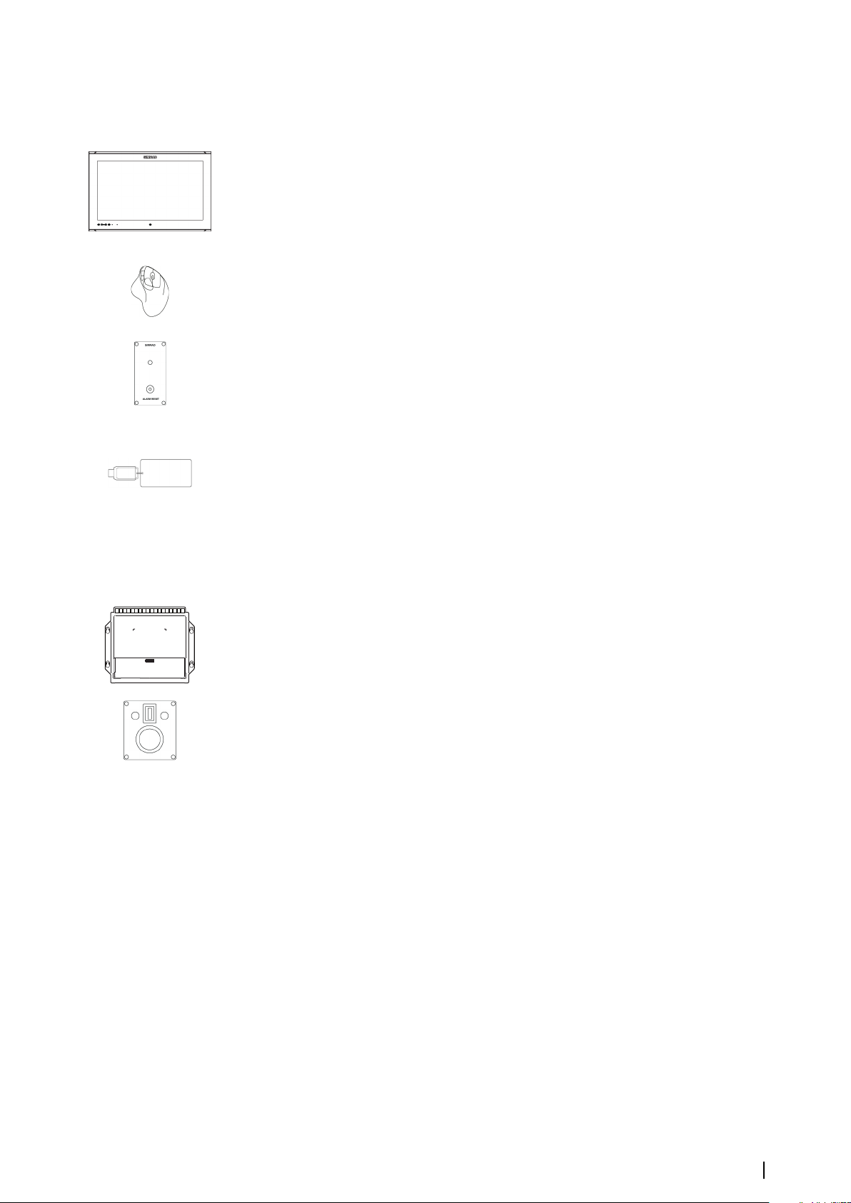
System components
The E5000 Processor
The E5000 Processor includes two independent CPUs, each with their own inputs and
outputs.
CPU1 is used for the ECDIS system. As an option, CPU2 can be used as part of an NSO MFD
(Multi-function Display).
The E5000 Processor is fitted with a MicroSD card slot. Both CPU1 and CPU2 may use the SD
card slot. If an SD card with charts (Navionics) is inserted into the slot, then the NSO (CPU2)
will automatically use the charts.
8
Introduction | E50xx ECDIS Operator Manual
Page 9
Two or more E5000 Processors can be connected through Ethernet to form a PLECDIS
(Paperless ECDIS) system.
TM
The Monitor
The E5024 system includes an M5024 monitor, the E5027 system includes an M5027 monitor.
The monitors are non-touch monitors, color calibrated and type approved for ECDIS.
A separate manual is delivered with the monitor. This manual includes installation and
operational instructions.
The trackball
A wireless trackball is used as pointing device in the system. The device is a standard
Logitech Wireless Trackball (M570).
The E0102 Alarm panel
The Alarm panel is the audio source for the system.
The unit gives an audible and a visual alert for any faults from the system, including power
supply failure.
Audible alerts are mandatory for any systems requiring Wheelmark certification.
The NavStick
A NavStick USB drive from NAVTOR is included in the system. The NavStick is used for chart
updates, and acts as the bridge between the E5000 Processor and a computer with internet
access.
When delivered from Navico the NavStick includes detailed world-wide charts. The detailed
charts on the NavStick are copied to the E5000 Processor when zones are purchased and
permit codes received from Navico.
SI80 Signal Interface unit
The optional SI80 Signal Interface unit is used for expanding the number of interface
channels. This unit includes a four channel NMEA 0183 interface computer board and
voltage supply for the CAN bus backbone.
LTSX50 Trackball
The optional LTSX50 is a panel mounted, water proof (IP68) trackball with scroll wheel.
The Chart database
The system is designed for using approved ENC charts in S57 or S63 formats.
A word-wide overview chart is pre-installed in the system. During installation and setup of
the system the required and detailed charts must be installed.
For details about chart installation procedure, refer to "Installing charts" on page 20.
Introduction | E50xx ECDIS Operator Manual
9
Page 10
The user interface
2
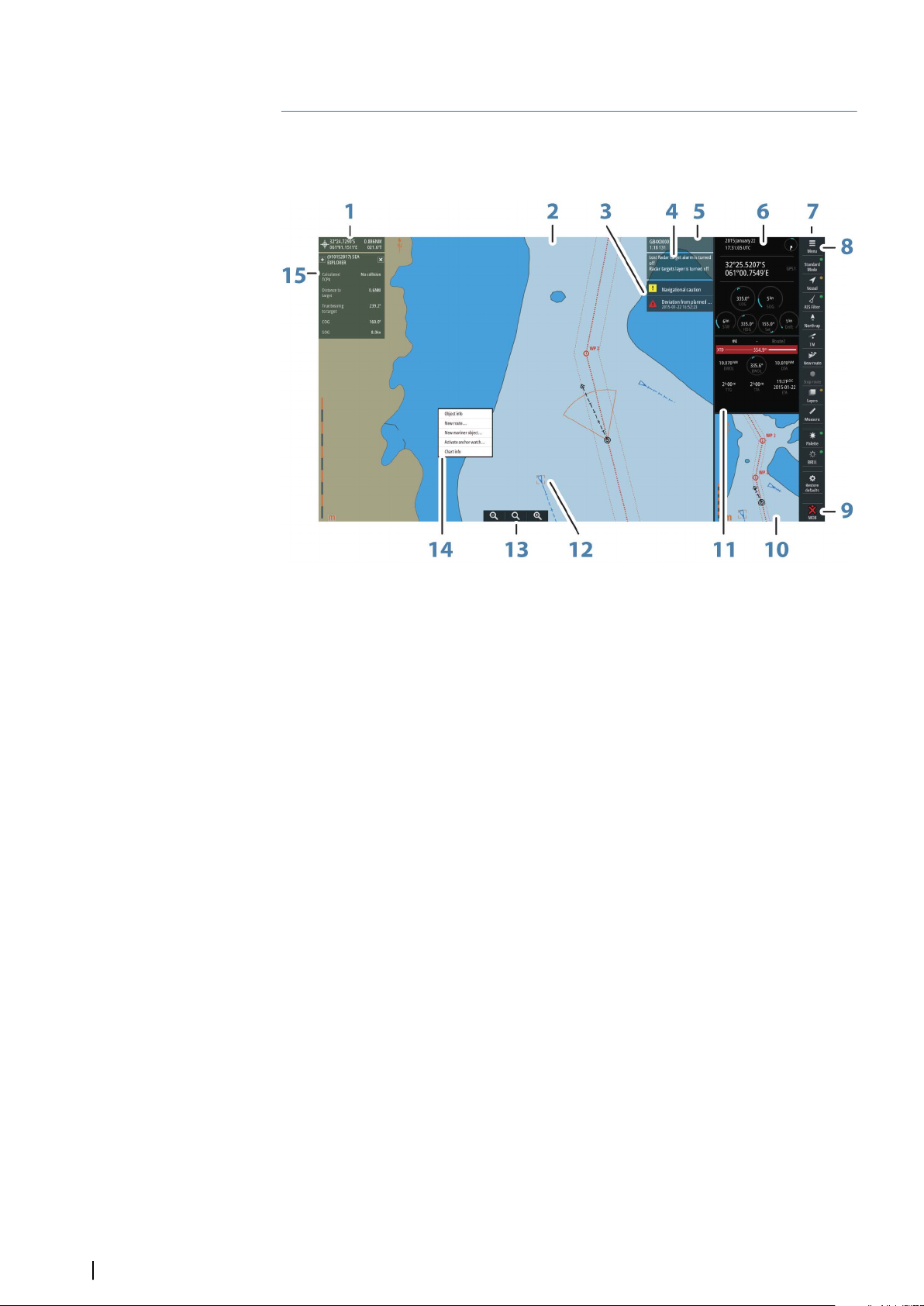
The main panel
The main panel is divided into predefined areas as shown in the figure below.
1 Cursor readout
2 Chart area
3 Alerts panel
4 Indications
5 Chart information
6 Instrument bar
7 Shortcut buttons
8 Menu button
9 Man Over Board button
10 Overview map
11 Navigation panel
12 Selected target
13 Zoom buttons
14 Panel menu
15 Target information
10
The user interface | E50xx ECDIS Operator Manual
Page 11
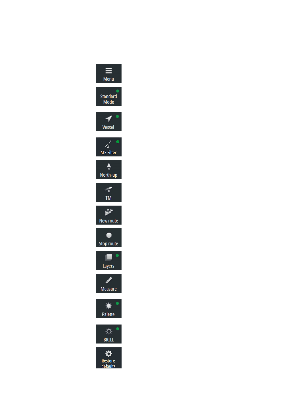
Shortcut buttons
Note: Some of the shortcut buttons have a light indicator that can be green or yellow.
Ú
Green indicates standard ECDIS mode, while yellow indicates non-ECDIS mode. Oneclick on a shortcut button with a yellow indicator reverts to ECDIS mode.
Menu
• Click to open the main menu
Display mode
• Click to return to Standard mode
• Right-click to show display mode options
Follow own vessel
• Click to move the chart view to the vessel position and then
follow the vessel. Vessel position in the chart depends on user
settings
AIS Filter
• Click to turn OFF AIS filter
• Right-click to display options
Orientation
• Click to loop through chart orientation options
• Right-click to display options
Motion
• Click to toggle vessel motion options
• Right-click to display options
New route
• Click to start creating a new route
Stop route
• Click to stop navigating an active route
Layers
• Click to turn OFF all layer options
• Right-click to display options
Measure
• Click to toggle measure function on/off
Palette
• Click to return to Night palette when Red and Black palette is
selected
• Right-click to display palette options
Brilliance
• Click to return to calibrated brightness for the selected palette
Restore defaults
• Resets settings to defaults set by the IEC standard.
The user interface | E50xx ECDIS Operator Manual
11
Page 12
Man Over Board (MOB)
• Click to create a MOB waypoint at the vessel's position
• Right-click to remove single or all MOB waypoints
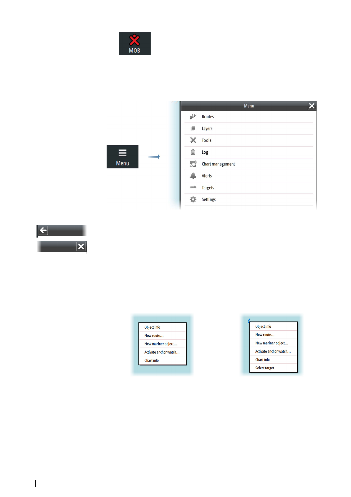
The Main menu
The Main menu is used for selecting options and for setting up the system.
The menu is displayed by selecting the Menu button.
You activate a menu item and toggle on/off a checkbox by selecting it.
A sub-menu is indicated with an arrow in the top left corner. Select this arrow to return to the
previous menu level.
You close the menu by selecting the X button.
The Panel menu
The Panel menu gives quick access to creating routes and mariner objects, and for displaying
details about chart and objects.
The Panel menu is displayed by pressing the right trackball key.
The content in the Panel menu depends on whether there are objects under the cursor
when you press the right trackball key.
Default Panel menu Panel menu when right-clicking a target
12
The user interface | E50xx ECDIS Operator Manual
Page 13

The Settings dialogs
The various Settings dialogs are used for setting up the ECDIS system.
All Settings dialogs are displayed as a full screen panel.
Sub-dialogs are indicated in the top of a dialog as shown below.
You close a Settings dialog by selecting the X button.
The user interface | E50xx ECDIS Operator Manual
13
Page 14

The Instrument bar
The Instrument bar includes time and position read from an EPFS (Electronic Position-Fixing
System) sensor, together with indicators for the system's main sensors.
Where multiple sensors exist, the information displayed is for the sensor with the highest
priority that is receiving data.
Valid sensors are indicated with a blue outline. Missing sensors or sensors sending invalid or
bad data have a yellow outline.
The Navigation panel
The Navigation panel is automatically activated when you start navigating a route. See
information in "Sailing along a predefined route" on page 54.
The Overview map
The Overview map makes it possible to display an overview or a detailed chart independent
of vessel position and chart scale in the main chart view.
In this panel the chart is always shown with north up.
There is no indication in the Vessel button if the vessel is not shown on the overview map.
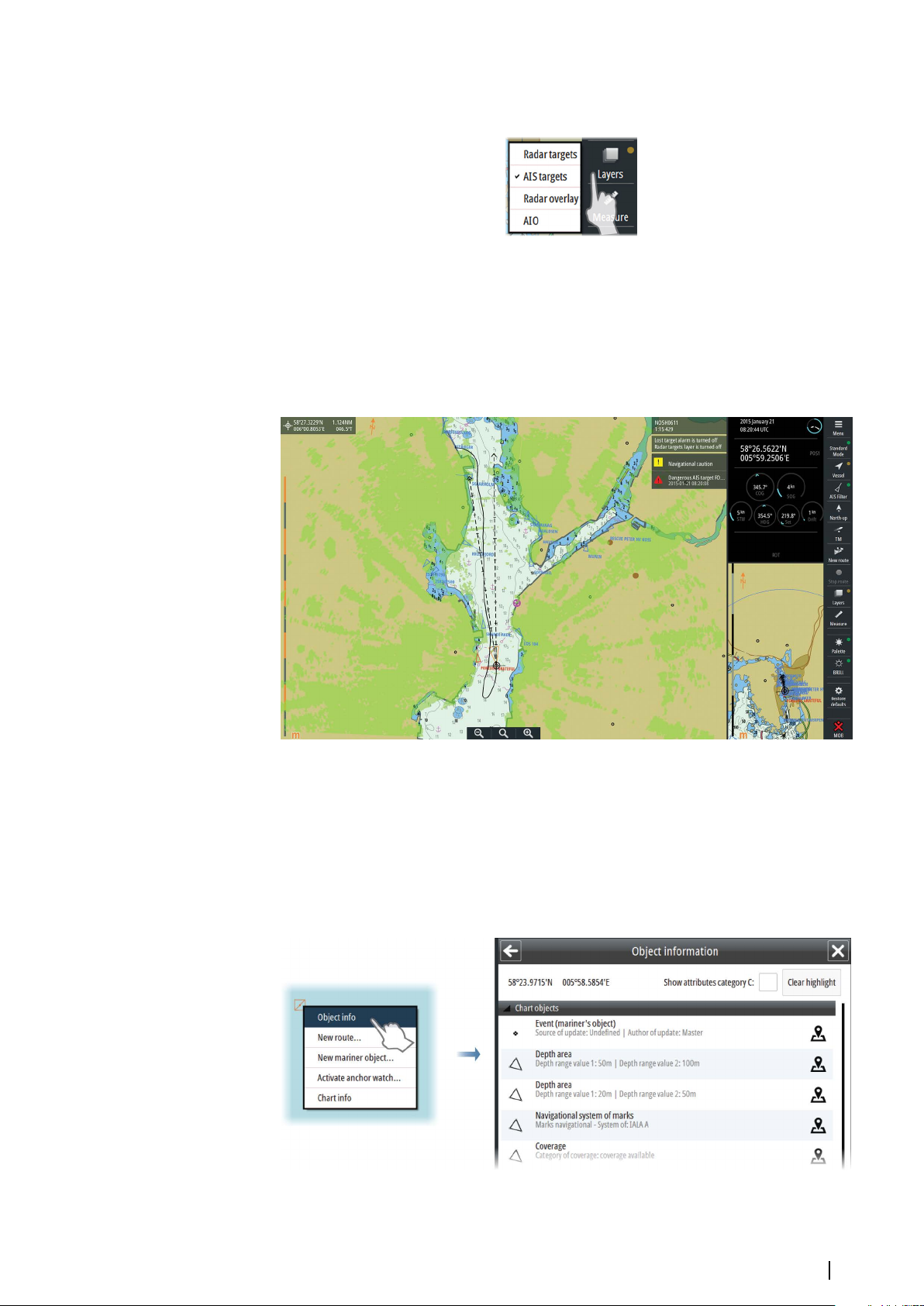
Layers
The system organizes chart overlay information in separate layers.
You turn these layers on and off from the Layers option in the main menu.
14
The user interface | E50xx ECDIS Operator Manual
Page 15
You can switch on and off all layers except User chart by right-clicking the Layers shortcut
button.
If any other layer than User chart is turned on, the light indicator in the Layers shortcut
button turns yellow.
You turn off all layers except User chart by left-clicking the Layers shortcut button.
Radar overlay
If a Simrad ARGUS radar is connected to the system, you can display radar overlay on the
chart.
Note: The Radar overlay has to be turned ON to see the radar image as an overlay on the
Ú
chart.
Object information
Information about an object is available in the Object information dialog.
The dialog is displayed by moving the cursor to the object and clicking the right cursor key.
The dialog shows a list of information for the selected object/area, and cursor position when
the right cursor key was pressed.
The number of objects in the Object information dialog depend on available information for
the selected area.
The user interface | E50xx ECDIS Operator Manual
15
Page 16
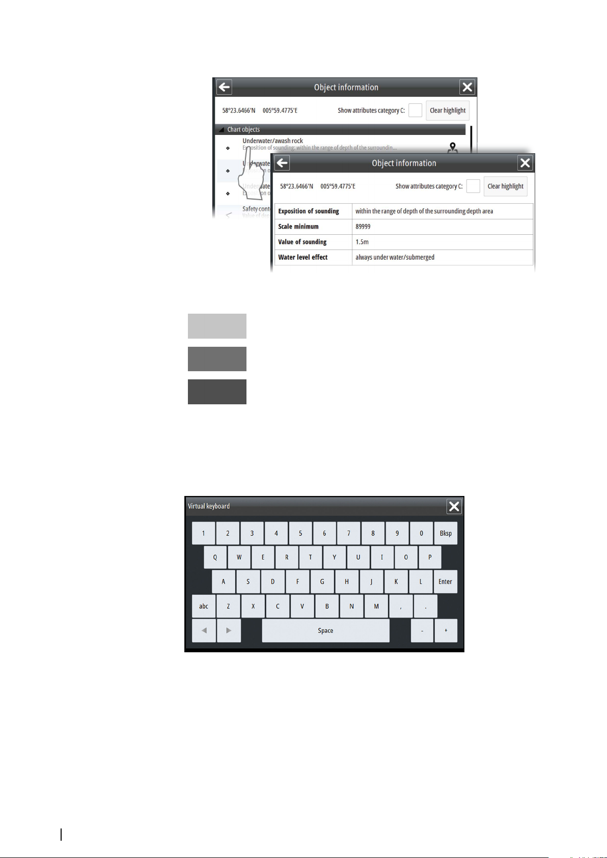
You display detailed object information by selecting an object item in the dialog.
Different icons are available in the Object information dialog:
Highlights the object in the chart, and moves chart center to the selected
object
Displays a txt file with additional object information in a separate window
Displays an image file related to the selected object
On-screen keyboard
A virtual keyboard is by default displayed when required for entering user information in
dialogs. The keyboard is operated by selecting the virtual keys.
You remove the keyboard from the panel by selecting the X in the upper right corner.
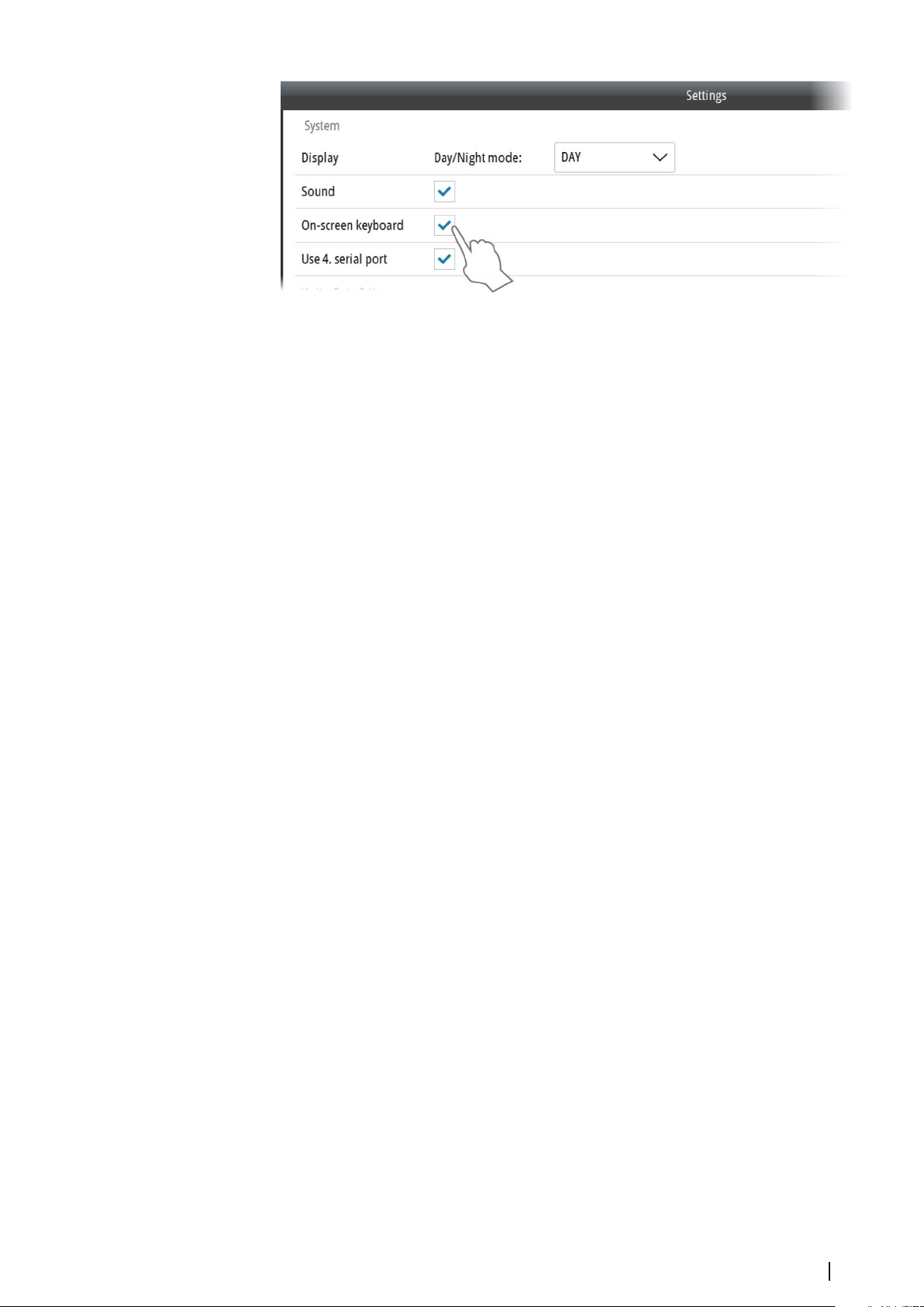
16
You can select to disable the keyboard from the System Settings panel.
The user interface | E50xx ECDIS Operator Manual
Page 17
The user interface | E50xx ECDIS Operator Manual
17
Page 18

Basic operation
3
Start-up
The system should be left with the power ON.
The system is switched on using the external power switch.
When power is switched on, the operating system will be started, automatically followed by
the system program.
When the system is switched on after the first-time initialization, the system will start with the
settings that were active when the system was turned off.
Turning the system off
The system is turned off by using the external power switch.
Note: Always let the system boot completely up before shutting it down.
Ú
Using the trackball
The trackball is used to position the cursor on the screen and to maneuver in menus and
dialogs.
The trackball keys have the following functions:
• Left key: used to click on buttons and operate menus.
• Right key: used to display the Object information dialog. Refer "Object information" on page 15
• The scroll wheel: used to increase/decrease the chart scale, for scrolling up/down in lists
and for editing values in text boxes
• The trackball: used for moving the cursor on the screen. The trackball can also be used for
panning the chart by holding down the left key.
Adjusting display brightness
Brilliance
The display brilliance is adjusted by the plus and minus keys on the M5024 and M5027
monitors.
The monitors are color calibrated from factory, and has its individual backlight brightness
setpoint in accordance with the ECDIS standard. ECDIS approved brilliance setting is
indicated with a green indicator in the BRILL shortcut button. If the brilliance is changed on
the monitors, the indicator changes to yellow.
Warning: Use of the Brilliance may inhibit visibility of information,
particularly when using the night pallete.
You return to ECDIS approved brilliance settings by selecting the BRILL shortcut button.
18
Basic operation | E50xx ECDIS Operator Manual
Page 19
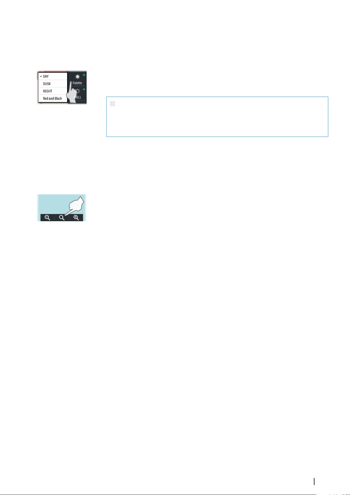
Display palettes
4 display palettes are available for optimum color contrast under different light conditions.
The Red and Black palette is not included in the ECDIS standard. When this palette is
selected, this will be indicated with a yellow indicator on the Palette button.
The display brightness is set by using the Palette button:
• Right-click to display and select palette options
• Left-click to return to ECDIS approved palette
Warning: Details in the chart may be less visible when one of the dark
palettes is selected. To increase the chart readability for the dark palettes,
select the 2 colors option in Portrayal settings. Refer "Portrayal settings" on page
25
Selecting the chart scale
Current chart scale is shown in the Chart Info panel.
The chart scale is changed by:
• scrolling up/down with the scrollwheel
• using the zoom buttons on the chart panel
Select the middle zoom button for selecting the best scale available for the vessel's position.
For more details see "Keep best scale" on page 28.
Moving the chart center
You move the chart by:
• Panning (moving the cursor while holding down the left cursor key)
• Left click to center the chart on the current cursor position
• Left clicking the Cursor read-out panel and then entering the selected position for the
chart center
You can also move the chart to a route or to a selected chart. See more information in
"Displaying a route" on page 48 and "Chart catalogs" on page 56.
Basic operation | E50xx ECDIS Operator Manual
19
Page 20

Installing charts
4
Installing charts from the NavStick
The system is delivered with a pre-installed overview chart. Detailed world-wide charts are
available on the NavStick USB drive included with the system.
The charts are installed and maintained by using the following services:
• NavTracker - a customized web interface from NAVTOR giving the navigator and ship
management full overview of chart usage, chart update history and chart management.
The customized NavTracker web interface is created and log-on details submitted to the
user when the charts are purchased
• NavSync - a PC program from NAVTOR used for receiving and updating the content on
the NavStick
The system allows for installing and using charts in S57 and S63 format from other chart
suppliers. Refer to "Installing charts from other suppliers" on page 23.
Before the charts can be copied from the NavStick to the system the following steps must be
performed:
1. Submit the User permit code to Navico
2. Verify your chart subscription from the NavTracker web site
3. Update the content of the NavStick to include chart updates and Chart permit codes
4. Copy content of the NavStick to the system
The next sections describe the required steps in detail.
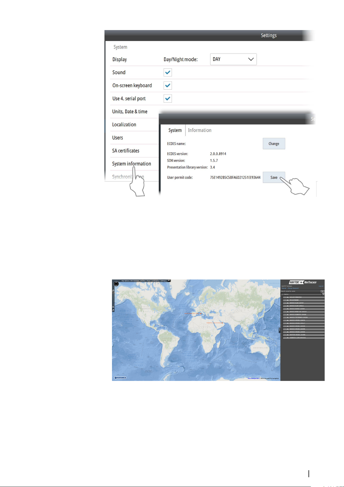
Submitting the User permit code to Navico
A chart permit code has to be obtained from Navico before the charts can be installed from
the NavStick. To obtain this code the system's User permit code must be submitted to
Navico.
The system's User permit code is automatically generated in the E5000 computer. If the
E5000 is replaced, a new User permit code has to be submitted to Navico to be able to use
the charts.
Insert a card in the SD card slot or a memory stick in the USB port on the E5000, and save the
User permit code from the System Information dialog. This code is sent to Navico by email
at chartservice@navico.com.
Note: You can NOT save the User permit code to the NavStick.
Ú
20
Installing charts | E50xx ECDIS Operator Manual
Page 21
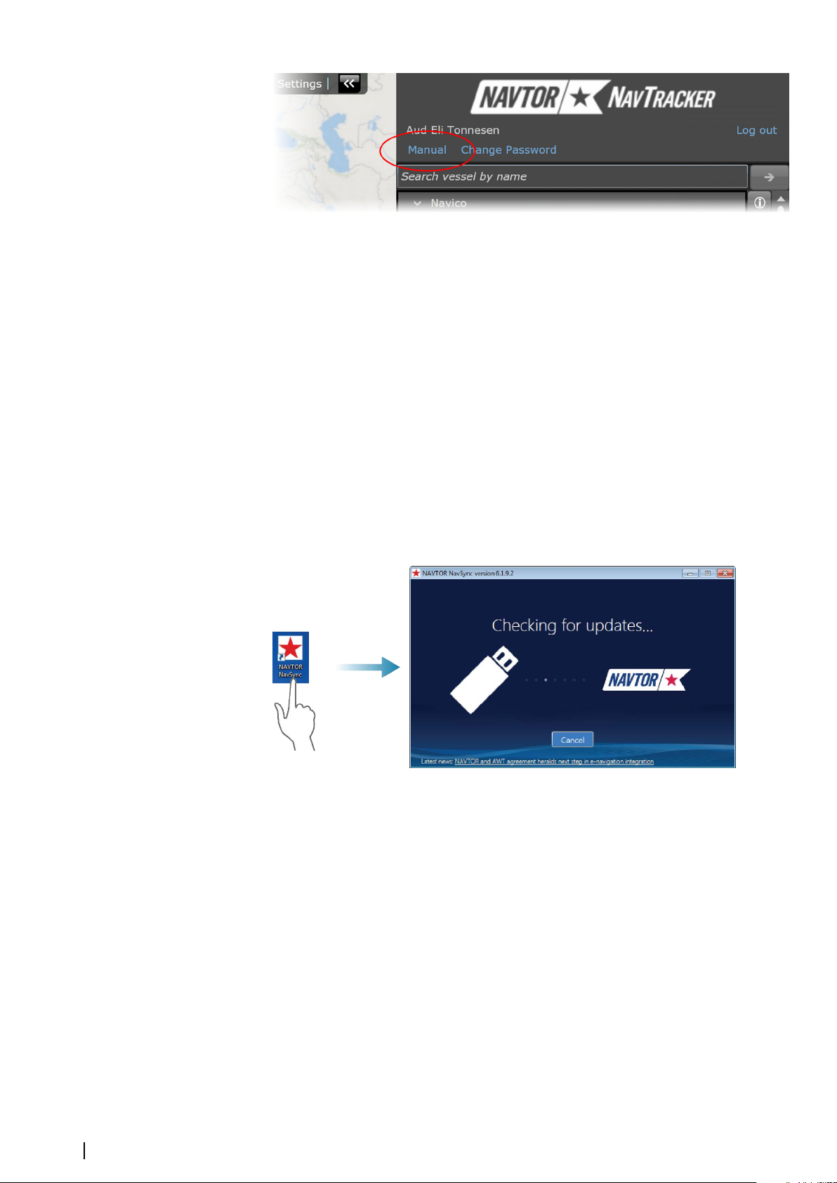
Verifying or changing your chart subscription
When Navico receives the User permit from the vessel and the chart subscription is agreed,
Navico creates a custom account and a customized web site in NAVTOR NavTracker. From
this web site you can view and manage your subscription.
You log on to this system via a web browser (http://navtracker.navtor.com/). You can use an
iPhone, iTouch or iPad app for viewing NavTracker information.
1. Log on to the NavTracker
2. Enter your email and password received from Navico when the subscription was agreed
3. Sign in to enter your customized NavTracker web site
4. Download the NavTracker User guide for detailed information about how to use the
NavTracker
Installing charts | E50xx ECDIS Operator Manual
21
Page 22
5. Verify that your subscription is correct, eventually request changes according to the
guidelines in the NavTracker User guide
When completed the NavTracker system updates your subscription information, and chart
updates and Chart permit codes for the purchased charts are prepared. These chart updates
and Chart permit codes are downloaded to the NavStick by using the NavSync program.
Note: The images from the NavTracker system are examples only.
Ú
Updating the content of the NavStick
When the chart subscription is agreed, available chart updates and Chart permit codes for
the purchased charts are prepared. These files are downloaded to the NavStick by using the
NAVTOR NavSync program.
1. Download and install the NavSync program from http://navsync.navtor.com/ on your PC
-
The NavSync icon are added to your desktop when the installation is completed
2. Insert the NavStick in the PC
3. Double-click on the NavSync icon to start the program
4. Follow the instructions on the screen to update the content of the NavStick with the
latest available charts
22
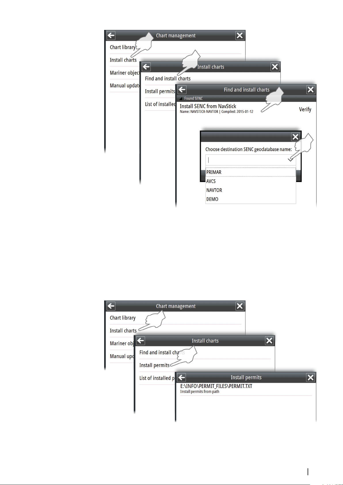
Copying the contents from the NavStick to the system
1. Insert the NavStick with the charts and the license code into the USB drive on the E5000
processor
2. Open the Chart management menu, and select Install charts
3. Select Find and install charts
-
The system will now automatically recognize the NavStick and list the content
4. Select the charts you want to install
Selected charts and license codes are now copied to the NAVSTICK-NAVTOR geodatabase.
Installing charts | E50xx ECDIS Operator Manual
Page 23
Installing charts from other suppliers
The chart suppliers have different procedures for submitting Chart permit codes and charts.
For chart suppliers other than NAVTOR it is required to install Chart permits before charts can
be copied to the system. Refer to the supplier documentation for details.
Note: A DVD drive is NOT included in the system type approval.
Ú
Note: Charts from vendors that use CD/DVD for distribution have to be copied to a USB
Ú
memory stick. The whole content of the CD/DVD has to be copied to the USB memory
stick before applying it to the E5000.
Chart permits are copied to the system by using the Install permits menu option.
When Chart permits are installed, the charts have to be copied from an USB or SD drive to
the system by using the Find and install charts menu option.
Installing charts | E50xx ECDIS Operator Manual
23
Page 24
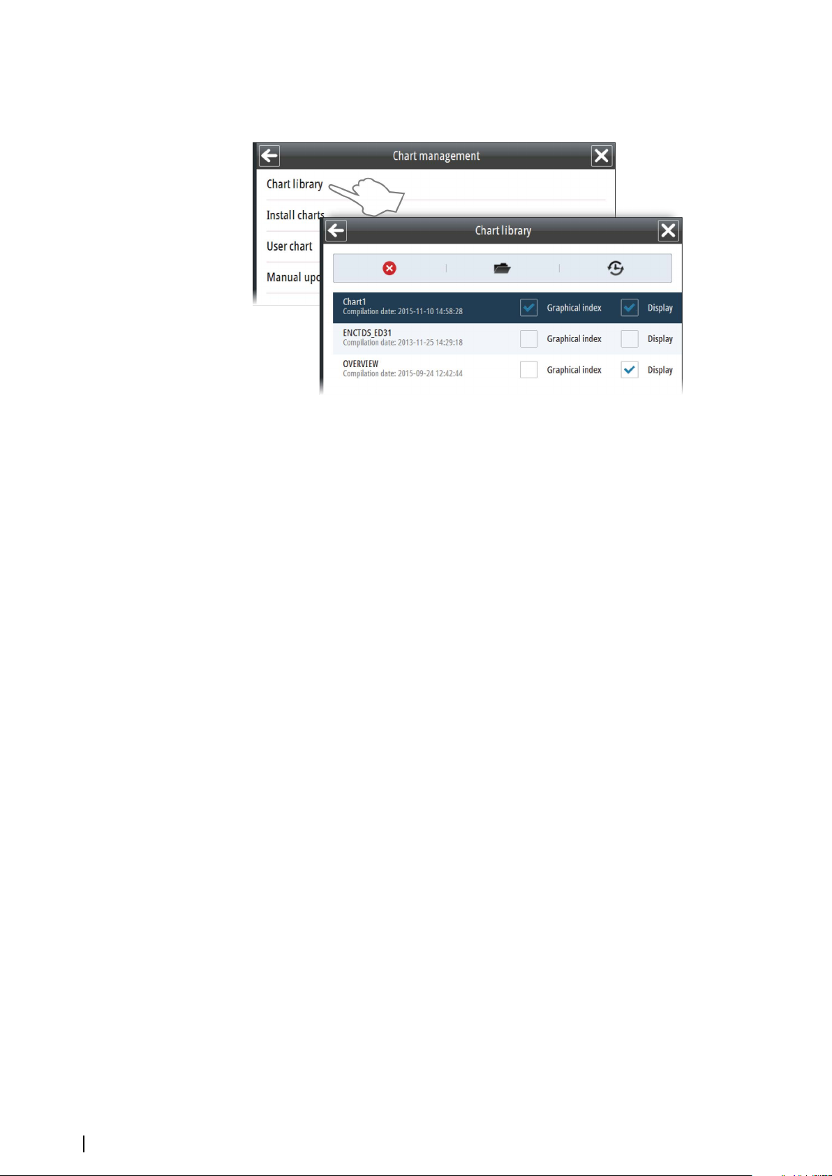
Selecting charts to display
All chart databases installed in the system are listed in the Chart library.
Select the Display option for the chart databases you want to use.
If you have more than one database available, you can select to show multiple charts. The
system will however only display one chart at the time, and it will automatically select the
best chart available based on your vessel's position .
24
Installing charts | E50xx ECDIS Operator Manual
Page 25
Setting up the chart panel
5
Chart settings
The chart settings are divided in 3 logical groups as described in the following sections.
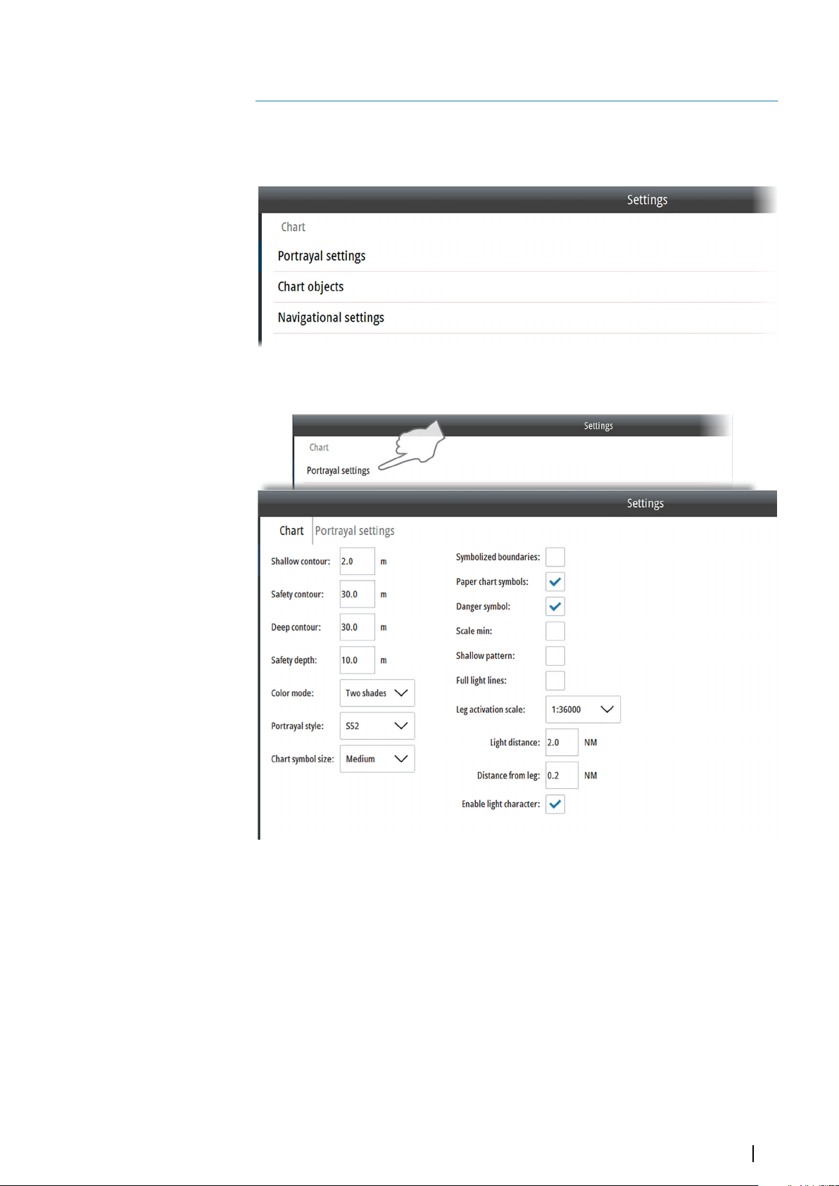
Portrayal settings
Setting up the chart panel | E50xx ECDIS Operator Manual
25
Page 26
Depth display settings
Various settings are available to visualize the depths and depth area:
• Shallow contour: Limit for shallow waters. Depth less than Shallow contour will be
displayed in dark blue color.
• Safety contour: Contour related to own vessel. To be used by the system to distinguish
between safe and unsafe water. Depths between Safety contour and Shallow contour
settings are displayed in medium blue color.
• Deep contour: Limit for deep waters. Depths between Deep contour settings and Safety
contour setting are displayed in light blue color.
• Safety depth: The ship's draft plus under keel clearance. Sounding are displayed in black
if they are equal to or more shallow than the safety depth settings. Soundings are
displayed in grey if they are deeper that the set value.
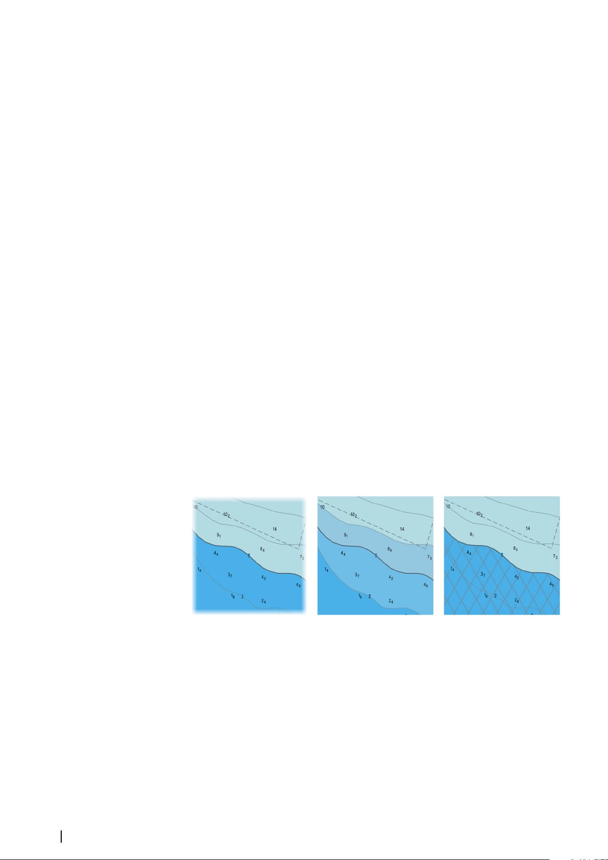
• Color mode: Number of colors used to indicate depth:
-
2 color mode: unsafe water (from the 0 meter contour to the safety depth) and safe
water (from the safety depth and deeper)
- 4 color mode: very shallow area (from the 0 meter contour to the shallow contour),
medium shallow area (from the shallow contour to the safety contour), medium deep
area (from the safety contour to the deep contour), and very deep area (from the deep
contour and deeper)
• Portrayal style: You can select to display the chart symbols in the S52 portrayal style or in
the INT1 portrayal style. The S52 portrayal style displays the chart symbols according to
the ECDIS standard, while the INT1 style displays the chart symbols and color as required
in the Symbols and Abbreviations Used on Admiralty Charts publication.
• Chart symbol size: Option for selecting size of chart symbols
• Symbolized boundaries: Displays boundaries lines as symbols rather than as plain lines
• Paper chart symbols: Displays navigation aids as paper chart symbols rather than as
simplified symbols. This option is available only for the S52 portrayal style.
• Danger symbol: Displays dangerous object with a danger symbol
• Scale min: Reduce the scale-dependent objects (objects with the attribute SCAMIN) scale
at which they are drawn. At display scales smaller than SCAMIN the object is not drawn.
For example, an object with a SCAMIN value of 50,000, indicating a scale of 1/50,000, is not
drawn on a display of 1/60,000.
• Shallow pattern: Fills the shallow area from the coast line to the safety contour with a
parallel pattern.
26
2 color mode 4 color mode Shallow pattern
• Full light lines: Displays light sector legs in real length rather than as short lines
• Leg activation scale: Set the scale to turn on the light sector feature. Additional options
appear:
Set the distance from the vessel to the navigation light (Light distance) and distance
from the vessel to the sector leg (Distance from leg) to determine when the sector
light is shown on the chart.
- Enable light character: Displays a blinking light character
Setting up the chart panel | E50xx ECDIS Operator Manual
Page 27
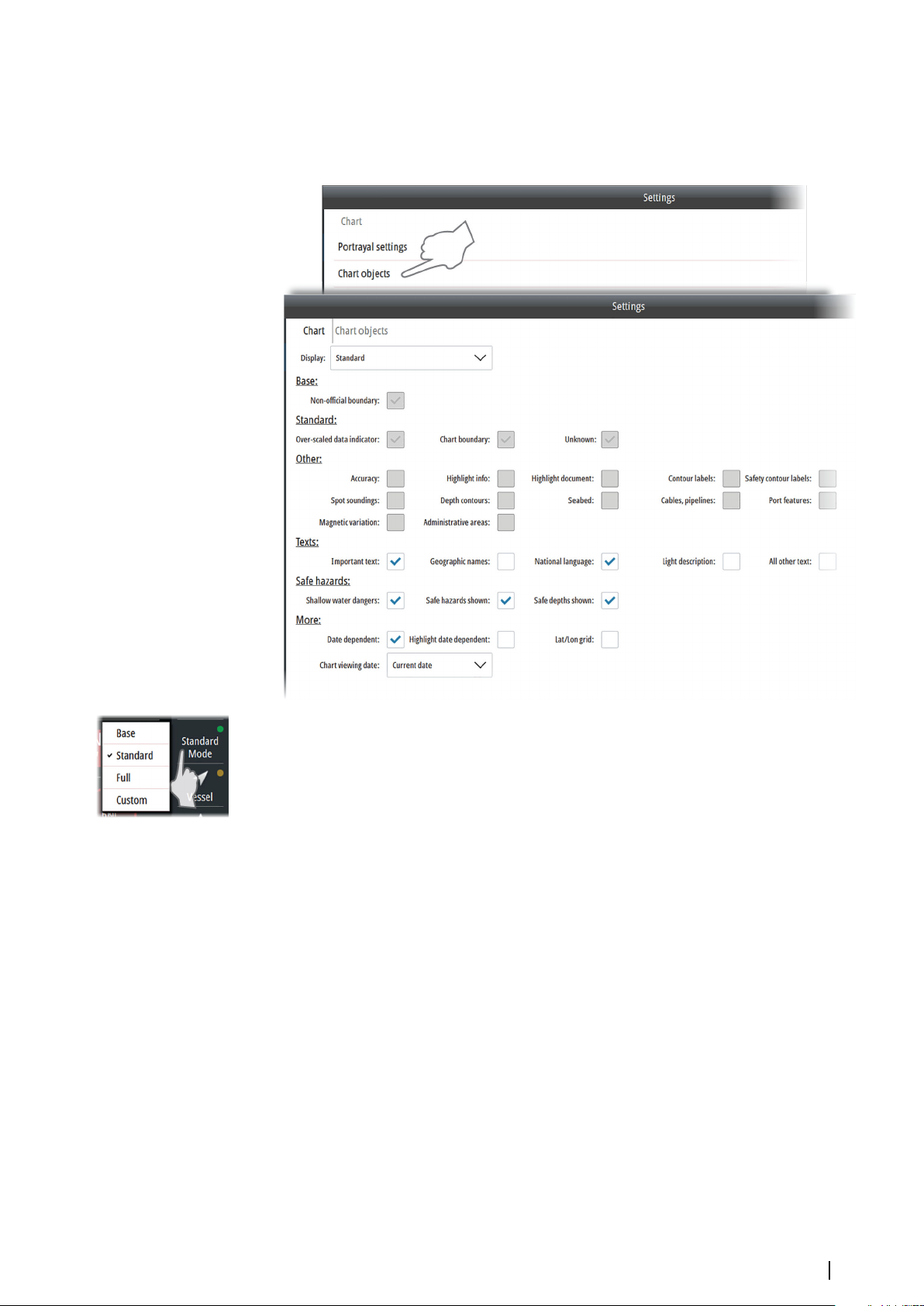
Chart objects
The system has 4 display modes. Base, Standard and Full mode have predefined standard
objects that are displayed. In addition these modes includes optional objects that manually
can be turned on. For the Custom mode all chart objects can be manually selected.
You select display mode by right clicking the Mode shortcut button, and you use the Chart
objects settings dialog to set up which optional chart object that should be displayed with
each mode.
Note: The Standard mode is the default ECDIS mode. If another mode is selected this is
Ú
indicated with a yellow indicator in the Mode shortcut button. You return to Standard
mode by selecting the Mode shortcut button.
Chart viewing date
Some objects on the chart can be date dependent. Change the chart viewing date in the
Chart objects settings dialog to see if new items appear, existing items have moved or are
removed from the chart on a particular date or date range.
Setting up the chart panel | E50xx ECDIS Operator Manual
27
Page 28
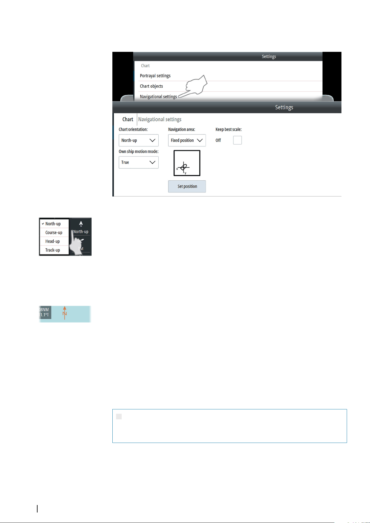
Navigational settings
Chart orientation
Several options are available for how the chart is rotated in the panel. You select the options
by right-clicking the chart orientation shortcut button.
• North-up: Displays the chart with north upward. Corresponds to the usual orientation of
nautical charts.
• Course-up: Displays the chart with the vessel’s course over ground directed upward. COG
is received from the active EPFS sensor.
• Head-up: Displays the chart with the vessel’s heading directed upward. Heading
information is received from a gyro compass or from a marine transmitting heading
device. If heading is not available, then the COG from active GPS is used.
• Track-up: Rotates the chart in the direction of the next waypoint when navigating a
route. If not navigating, the heading up orientation will be used until navigation is started
The north arrow in the top left corner of the panel shows the north orientation.
Navigational area
The Navigation area setting defines where your vessel is displayed in the chart view.
• Fixed position: Used for setting the position on the screen where you want to display
the vessel.
Press the Set position button to close the dialog and display the chart panel, allowing you
to manually select the preferred position for vessel. The display returns to displaying the
vessel in this position whenever you press the Vessel shortcut button
• Area: Used for manually defining the navigation area for true and relative motion.
In true motion the chart is redrawn with the vessel on the outer circle when the vessel
reaches the inner circle. In relative motion the vessel's position in the chart is on the outer
circle
Warning: The navigation area options must be used with care. The
manually selected vessel position and area must be set considering safe
navigation!
Keep best scale
When the Keep best scale option is selected, the system automatically displays the chart with
the largest scale available for the current position of the vessel.
28
Setting up the chart panel | E50xx ECDIS Operator Manual
Page 29
Note: The Keep best scale option is turned off when you manually zoom the chart. You
Ú
can temporarily display the best scale available by pressing the best scale zoom button,
but this does not turn on the Keep best scale option.
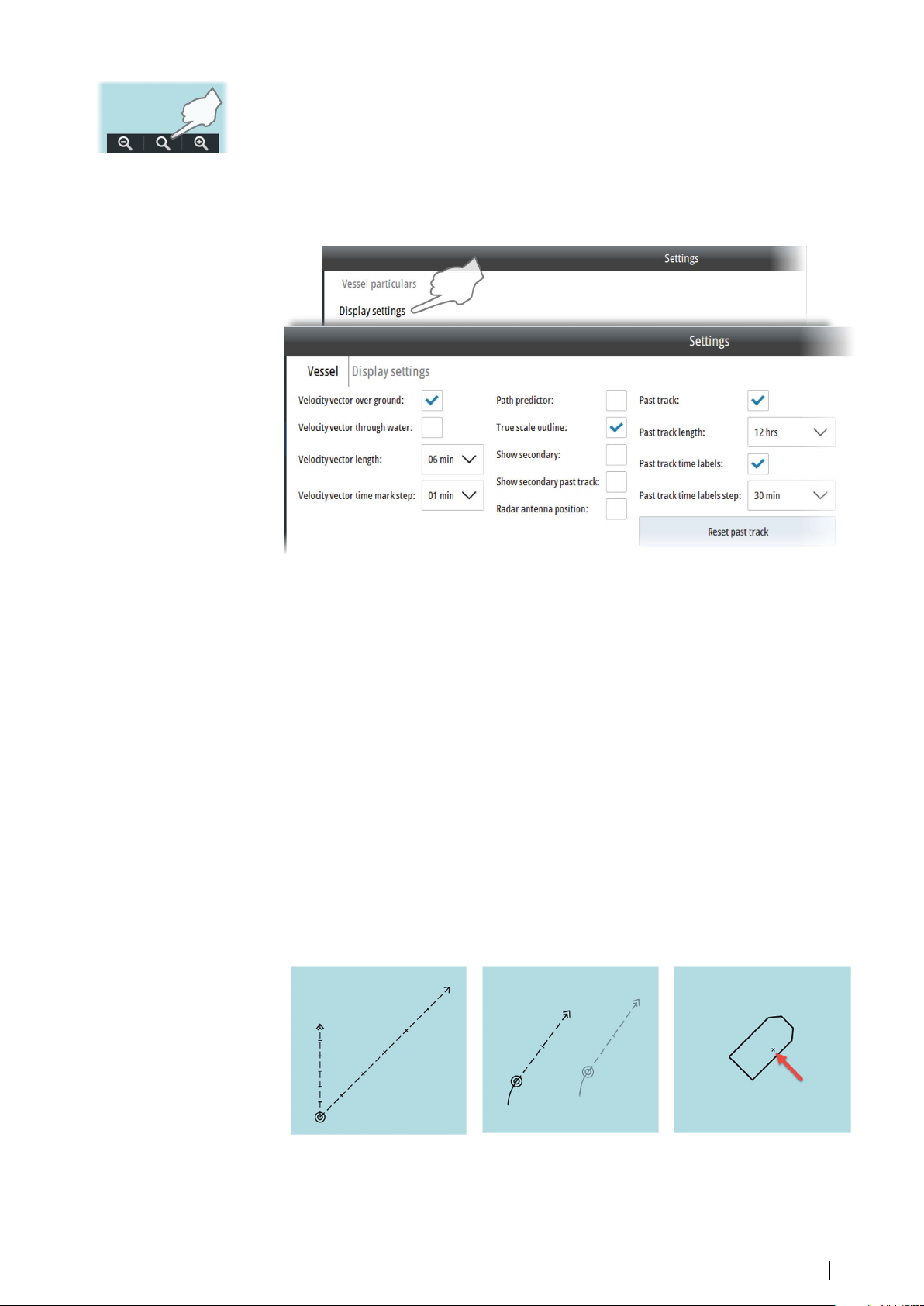
Own vessel's display settings
You select how your own vessel is displayed on the chart panel from the Vessel Display
settings dialog.
The following options are available:
• Velocity vector settings: Velocity vector of the vessel is a vector predicting position of
the vessel in a specified period of time based on the current speed and course. Two
velocity vectors are available: Velocity vector over ground based on speed over ground
and course over ground, and Velocity vector through water based on speed through
water and heading. You select the vector length in minutes and the time between the
marks on the vector
• Path predictor: Along with the velocity vectors you can display a path prediction vector.
Path predictor is based on speed over ground, course over ground and rate of turn
• True scale outline: Displays the vessel with a true scale symbol at large chart scale. The
symbol size is based on the vessel characteristics settings
• Show secondary/Show secondary past track: Displays the vessel's past position and
past tracks read from the secondary sensors. Data from the sensor in use is drawn with
black lines. If there is valid data from sensors not in use, these appear as greyed
• Radar antenna position: Indicates the radar antenna position on own vessel outline or
symbol
• Past track settings: Displays the vessel's past tracks on the chart. You select the track
length in minutes and the time between the marks on the track. The past track length,
time marks, mark steps and reset option affect tracks for both primary and secondary
sensors.
Velocity vectors
Setting up the chart panel | E50xx ECDIS Operator Manual
Primary and secondary sensors True scale outline with radar antenna
position
29
Page 30
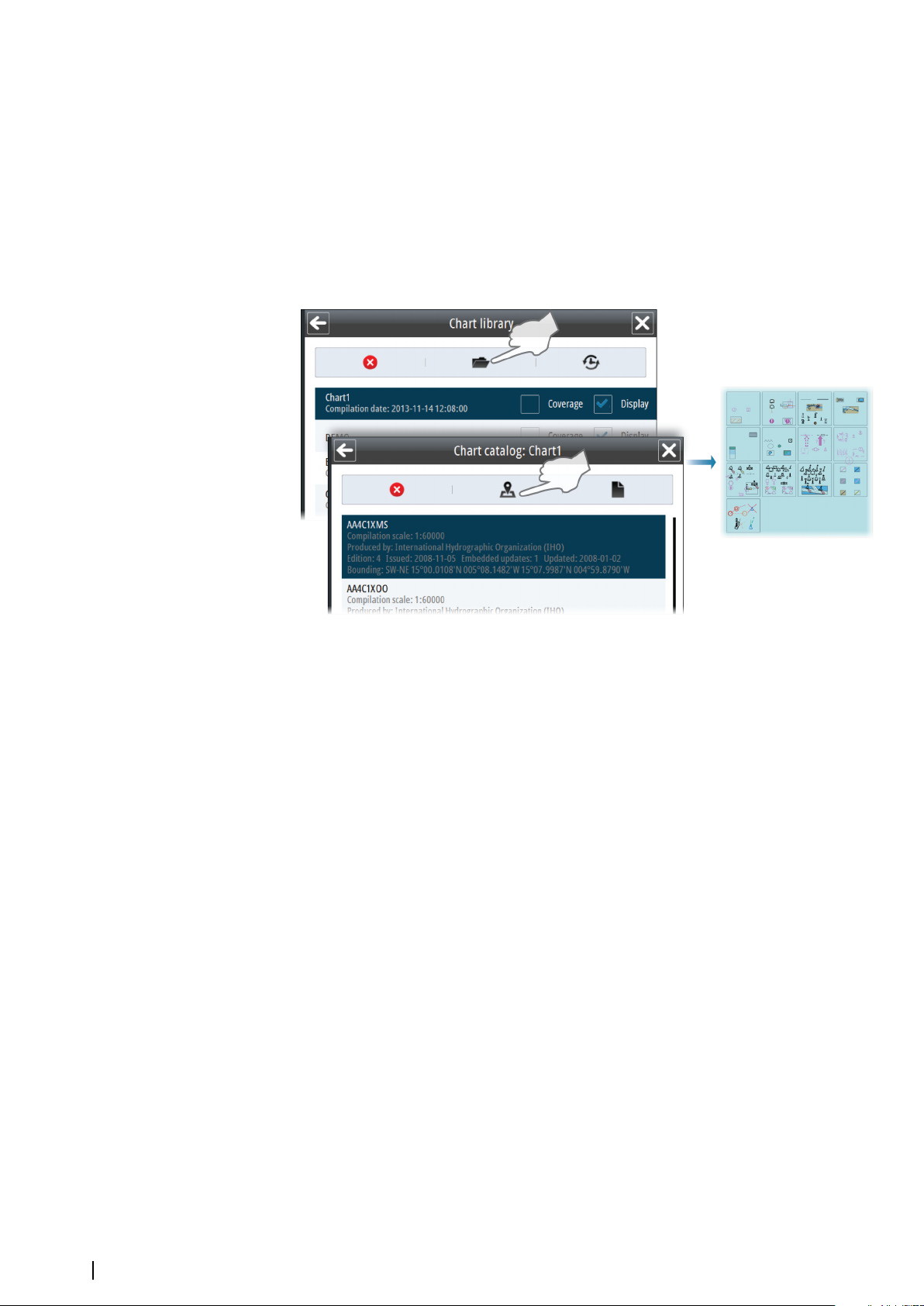
Chart symbols
All chart symbols used by the system can be displayed as follows:
1. Open the Chart library panel
2. Open the chart catalog for the Chart1 database
3. Select the Display Object icon for one of the datasets included in the database
-
The display moves and scales the chart to show all symbols included in the selected
dataset
4. Right-click a symbol to display object information
5. Return to the Chart library panel and select your preferred chart database to go back to
normal operation
30
Setting up the chart panel | E50xx ECDIS Operator Manual
Page 31
Tools for safe navigation
6
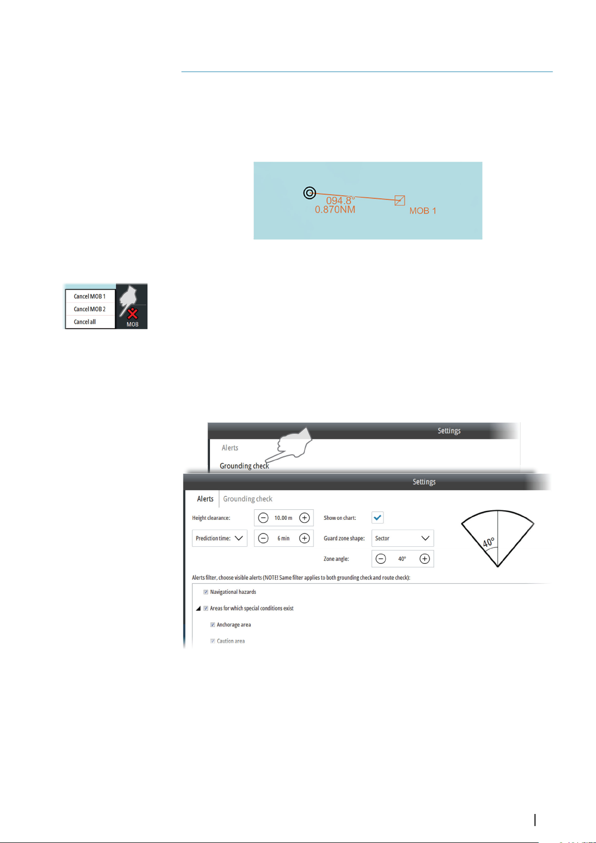
Man Over Board
If an emergency situation should occur, you can save a Man Overboard (MOB) waypoint at
the vessel’s current position by selecting the MOB shortcut button.
Bearing and Range from the MOB to the vessel’s position are displayed on the chart.
If the cursor is moved to the marker and the left cursor key pressed, the MOB position is
displayed in the Object information dialog.
A MOB cannot be moved. Individual or all MOBs are removed by right-clicking the MOB
button.
Setting a guard zone around the vessel
The grounding check option is used to warn you about dangerous and caution objects
inside a specified zone ahead or around your vessel.
The grounding alert is based on if your vessel will cross the Safety contour setting or the
Safety depth setting. Refer to "Depth display settings" on page 26.
If an object is within the guard zone, a navigational caution is displayed in the Alert panel.
This caution will remain in the Alert panel as long as the condition remains.
The following values should be defined:
• the height required for your vessel to pass under a crossing overhead object
• the prediction time or safety distance
• the guard zone shape
You should also set the Safety contour setting and the Safety depth setting. Refer to "Depth
display settings" on page 26.
You can select to display the guard zone on the chart.
Tools for safe navigation | E50xx ECDIS Operator Manual
31
Page 32

Guard zone: Sector Guard zone: Cardioid
Note: If the guard zone is displayed on the chart, dangerous objects inside the zone are
Ú
indicated as red, and caution objects indicated as yellow. There is no indication of
dangerous objects within the guard zone if the guard zone is not displayed on the chart.
Displaying information about navigational cautions
Navigational cautions are displayed in the Alerts panel.
You display details about a caution by right-clicking Navigational caution.
Filtering alert items on the chart
Too many visible alert items can clutter the chart. The visible alert items can be filtered so
they are shown or not shown on the chart. Toggle ON/OFF the visible alert items in the
Grounding check dialog.
Note: This filter does not filter alert messages. Alert messages continue to appear in the
Ú
Alerts panel regardless of this filter setting. It only filters the visible alert items on the
chart. For example, if you filter off Navigational hazards, then the hazards are not
displayed on the chart but a hazard alert will appear in the Alerts panel if you sail into a
hazard.
Showing distance lines and zone rings
The system includes two options for indicating a distance from your vessel to other chart
objects:
• Parallel index lines
• Range rings
Note: Index lines and range rings do not activate any alerts.
Ú
32
Tools for safe navigation | E50xx ECDIS Operator Manual
Page 33

Parallel index lines
One or two index lines can be positioned on the chart. A single Index line is used to visualize
a distance to the vessel or to land objects, either parallel to or in front of the vessel. Two
index lines can be used to indicate a corridor - typically used to visualize an area you want to
maneuver within.
The bearing of an index line is measured from the true north direction. To draw a line parallel
to the vessel the bearing must be set equal to the vessel's true heading. To draw a bearing
line on the opposite side of the vessel the bearing must be offset with 180°.
Note: The bearing of parallel index lines do not follow the vessel's heading!
Ú
The distance to an index line is measured along the perpendicular from the own vessel's
Common Reference Point (CPR) to the index line.
Single Index line - perpendicular to vessel's heading Index lines parallel to vessel heading
Range rings
The range rings are used to indicate up to ten circular distances to your vessel. The rings are
fixed relative to the vessel and will move with the vessel.
You define the distance from the vessel to the first range ring and the steps between the
rings.
Measuring distance and bearing
The cursor panel shows the cursor's coordinates, range and bearing from the vessel to the
cursor. You can therefore use the cursor to measure a distance from your vessel to any chart
object.
You can also use Electronic Bearing Lines (EBL) and Variable Ranger Marker (VRM) feature to
measure distance and bearing.
Tools for safe navigation | E50xx ECDIS Operator Manual
33
Page 34

1. Select the Measure shortcut button to activate the EBL/VRM feature
-
A circle is drawn with the center at the vessel position
- An information panel in the display's lower right corner shows range and true bearing
from the circle center to cursor position. The first line shows range and bearing along
the great circle line, the second line shows range and bearing along the rhumb line
2. Move the cursor to the object to which you want to measure range and bearing
3. Move the cursor to an object and press the left cursor button to move the circle center.
You can then move the cursor to measure the distance between the new circle center
and another object in the chart.
4. Re-press the left cursor button to move circle center back to the vessel
You stop the measuring function by re-selecting the Measure shortcut button.
Navigational calculations
Geodesic calculation
This is a tool used for calculating a position based on a known starting position, the bearing
and the distance to the position you want to calculate. You can also do the calculation in
reverse and calculate bearing and distance between two known positions.
You can select whether you want to use rhumb line or great circle calculation.
34
Great circle approximation
The system can calculate waypoints between two coordinates using great circle
computation.
1. Enter the latitude and longitude for start and end point for the route
2. Select method for positioning the waypoints, either with equal distance or equal arc
3. Select distance between the waypoints
4. Select Calculate to display the list of the calculated waypoints
Tools for safe navigation | E50xx ECDIS Operator Manual
Page 35
Datum transformation
This function is used for converting position information from the active dataset format to a
selected target data format.
Enter latitude and longitude, and select the Forward or Inverse buttons to convert the
position to the selected format.
Manually calculating vessel position
When no GPS is available, the Lines Of Position function (LOP) can be used to calculate your
vessel's position.
The LOPs can be positioned based on known bearing and/or on distance to the selected
objects. The following guidelines apply:
• Two bearing LOPs or 2 distance LOPs will give you an inaccurate position
• Three bearing LOPs give an accurate position if the length of the line from the objects to
the crossing point is less than 0.5 NM
• A combination of 1 bearing LOP and 1 distance LOP gives an accurate position
The system will automatically calculate an estimated position based on the plotted LOP’s.
You can use this information to update the own ship position during dead reckoning
operation.
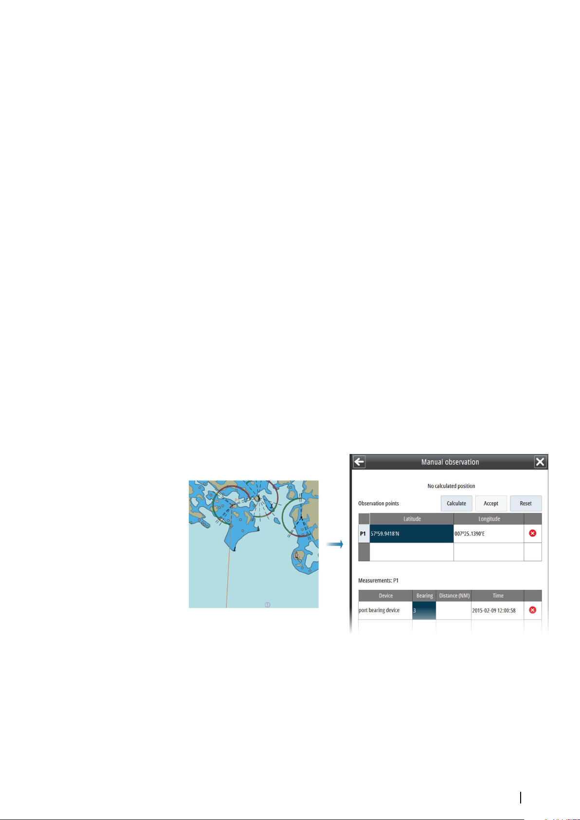
In the example and illustrations below two bearing LOPs are used to calculate the position.
1. Select Manual observation from the Tools menu to display the manual observation menu
2. Select the empty Latitude field in the Observation points table
The object is labelled with P1 and an observation object symbol, and the object's
3. -
coordinates are listed in the Observation points table
Move the cursor to the first observation point in the chart and press the left cursor button
- A second empty row is added to the Observation points table
4. Double-click any of the observation point fields if you want to manually edit the position
5. Select the identification of the equipment used to measure bearing to the observation
point, and enter the bearing to the observation point
- The first bearing LOP is drawn in the chart based on the input values
6. Repeat step 2, 3, 4 and 5 to position the second observation point (P2)
The second LOP is drawn in the chart based on the input values
-
- Previously taken measurements are automatically corrected according to the distance
own ship traveled between the measurements
Tools for safe navigation | E50xx ECDIS Operator Manual
35
Page 36

7. Select the Calculate button to confirm the observation points' position and
measurement
-
The calculated position is displayed in the upper right part of the manual observation
menu, and the estimated position (EP) is indicated in the chart
8. Select the Accept button to use the calculated position for dead reckoning
The Dead reckoning values are updated
-
- The labelled position in the chart is changed from EP to DR
9. Select Enable correction if you want to manually update the dead reckoning position
The vessel's icon is moved to the calculated dead reckoning position.
36
Anchor watch
The system provides an anchor watch feature. When activated, the system sends an alert
when the vessel moves a set distance from the anchor spot.
Anchor watch setup
Use the Vessel performance characteristics dialog to set the Anchor location relative to the
common reference point and the swing circle radius.
Tools for safe navigation | E50xx ECDIS Operator Manual
Page 37

Activating the anchor watch
To activate the anchor watch feature, right-click the chart when you drop your anchor and
select the Activate anchor watch panel menu option. When you activate the anchor watch
feature, the system displays the swing circle radius setting in the Anchor watch dialog. You
can change the setting in the Anchor watch dialog.
Turn off the anchor watch
To deactivate the anchor watch feature, right-click the chart and select the Deactivate
anchor watch panel menu option.
Tools for safe navigation | E50xx ECDIS Operator Manual
37
Page 38
7
Other vessels on the chart panel
Other vessels’ movement can be displayed in the chart by connecting an AIS system or an
ARPA radar to the system.
The system can alert the user about potentially dangerous targets and loss of
communication with a target.
AIS and ARPA targets are displayed in separate layers. The layers can be toggled on/off by
right-clicking the Layers shortcut button.
Note: If any other layer than Mariner objects is turned on, the light indicator in the Layers
Ú
shortcut button turns yellow. You turn off all layers except Mariner objects by leftclicking the Layers shortcut button.
The system does not have any limits for maximum number of AIS or ARPA targets. However,
warnings are issued as follows:
• ARPA targets:
- A 95% limitation warning is issued when 38 targets is reached
- A 100% limitation warning is issued when 40 targets is reached
• AIS targets:
- A 95% limitation warning is issued when 950 targets is reached
- A 100% limitation warning is issued when 1000 targets is reached
AIS targets
AIS target symbols
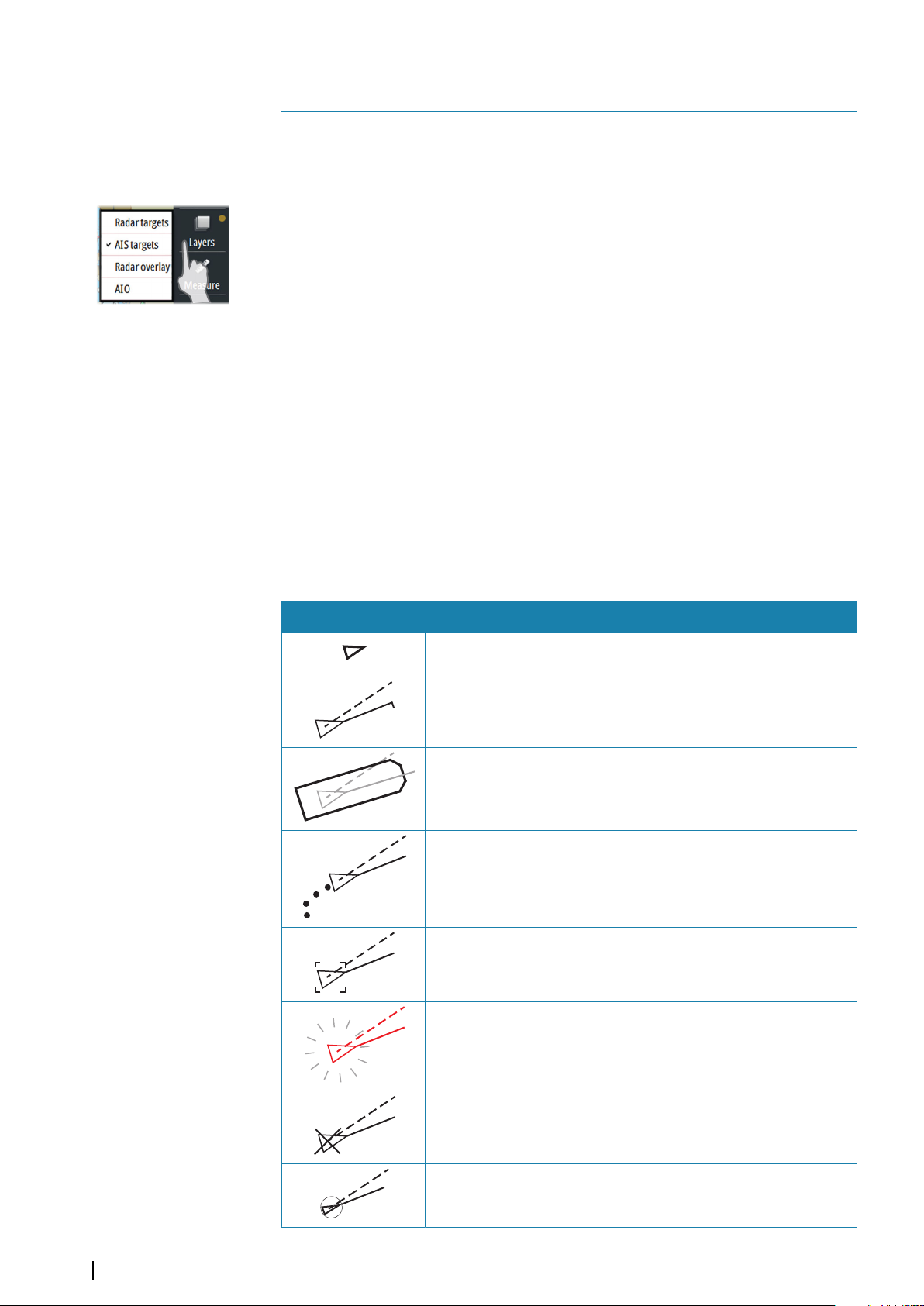
The following icons are used for AIS targets in the system:
Symbol Description
Sleeping AIS target, aligned with received heading information or
with COG information if heading is not available
AIS target with heading line and SOG/COG (dotted line), and with
indicated turn direction
AIS target with true scaled outlines
AIS target with past track
Selected AIS target, indicated with a square (dotted line) around
the target symbol
38
Dangerous AIS target indicated with bold line and with red color.
The symbol flashes until the target alarm is acknowledged by the
operator
Lost AIS target, indicated with crossed lines centered on the target
symbol. The symbol is located at the last received position from the
target
Associated target - using AIS data
Other vessels on the chart panel | E50xx ECDIS Operator Manual
Page 39
Symbol Description
+
AIS SART (AIS Search And Rescue Transmitter)
AIS Base station
Real AtoN (Aids To Navigation)
Virtual AtoN
For a complete list of AIS and AtoN symbols, refer to "Target symbols" on page 81.
Note: A symbol is drawn with a dotted line if the collision avoidance cannot be
Ú
calculated.
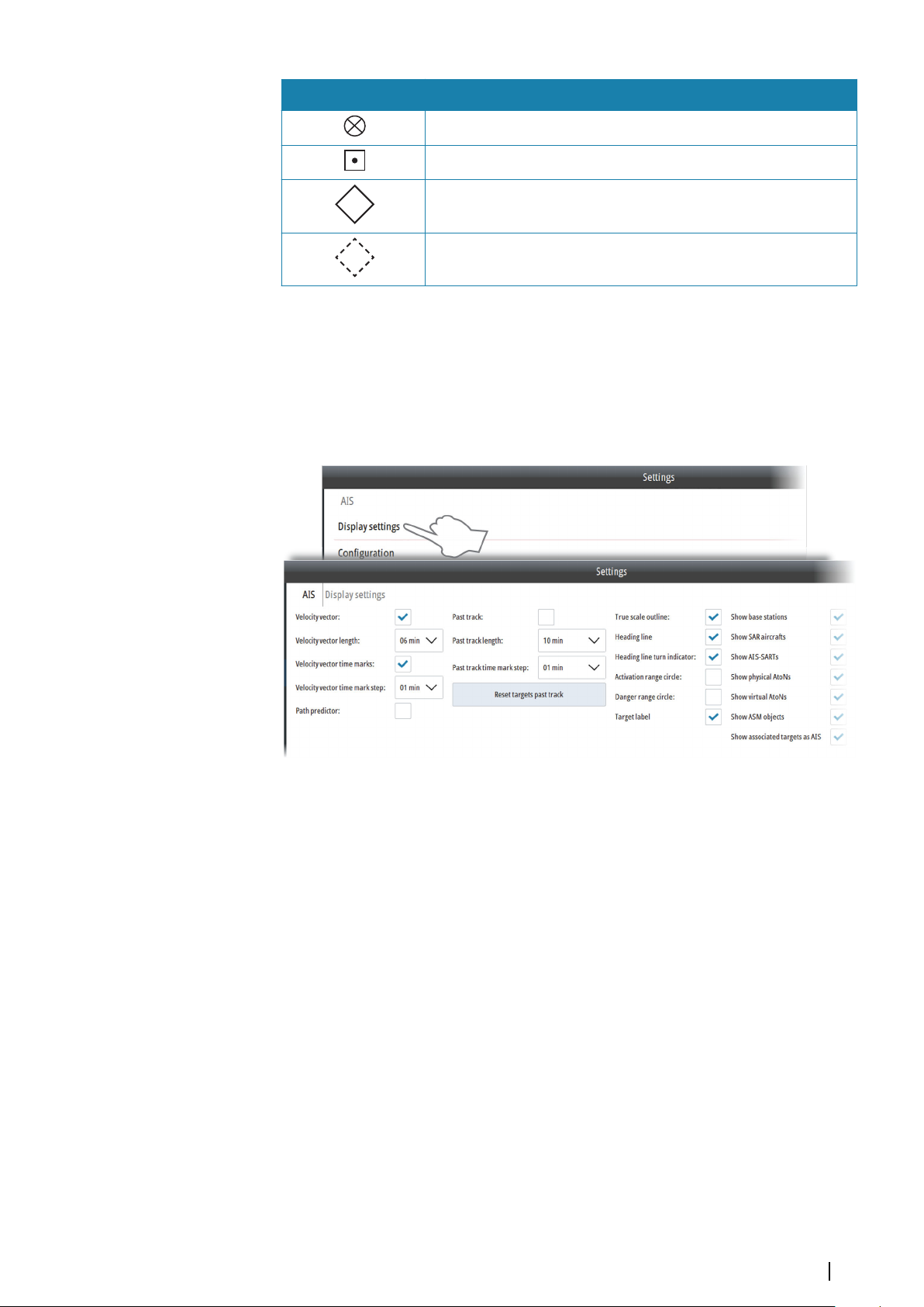
Display settings for AIS targets
You select how the AIS targets are displayed on the chart panel in the AIS Display settings
dialog.
• Velocity vector: Predicted position of the target in a specified period of time based on
the target's current speed and course over ground (SOG and COG). Time marks and steps
between each mark can be defined and added to the view
• Path predictor: Predicted vector based on speed over ground (SOG), course over ground
(COG) and rate of turn
• Past track: The target's track over a set time period. Time stamps can be added to the
track line
• True scale outline: Displays the targets as true scale symbols in large chart scale. The
displayed size is based on dimensions received in the target's AIS messages
• Heading line: The target's heading and eventually turn direction pointing in the direction
of the turn
• Range circles: Circles added relative to own vessel position to show the ranges where a
target is visible, active or defined as dangerous
• Target label: Target name as received in the AIS message
• Show AIS targets: Select to show specific AIS target types on the chart
• Show associated targets as AIS: Displays associated Radar/AIS targets as AIS. To enable
AIS/Radar targets associations, refer to "Configuring Radar targets" on page 43.
Configuring AIS targets
You specify the distance for when an AIS target should be activated and considered
dangerous from the AIS Configuration dialog. From this dialog you also define when a lost
AIS target are removed from the chart view.
Other vessels on the chart panel | E50xx ECDIS Operator Manual
39
Page 40

Note: You specify when an AIS target should be visible on the chart using the AIS Filter,
Ú
refer to "AIS functions" on page 40.
Note: You can select to display the distance limits. See Display settings for AIS targets.
Ú
AIS functions
Use the AIS Filter option to filter the AIS objects on the chart, set your vessel AIS status, and
for communicating with another vessel's AIS system.
Right-click the AIS Filter shortcut button to display options. Select the Filter enabled option
to apply the filter.
AIS target filter settings
Use the AIS Filter settings option to specify when and which AIS sleeping targets should be
visible on the chart. Hiding sleeping targets can reduce chart clutter.
Note: You specify the distance for when an AIS target should be activated and
Ú
considered dangerous using the AIS Configuration dialog. From the AIS Configuration
dialog you also define when a lost AIS target are removed from the chart view. Refer to
"Configuring AIS targets" on page 39.
40
Other vessels on the chart panel | E50xx ECDIS Operator Manual
Page 41

AIS messages
Use the AIS messages option to create and view sent or received AIS messages.
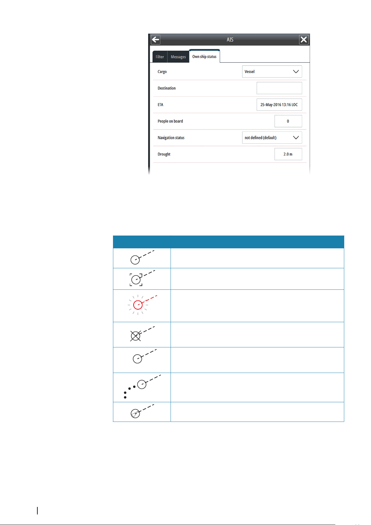
AIS own ship status
Use the AIS own ship status to set the status of your vessel which is seen by other vessels.
Other vessels on the chart panel | E50xx ECDIS Operator Manual
41
Page 42
Radar targets
R
18
Radar target symbols
The following symbols are used for radar targets in the system:
Symbol Description
Tracked Radar target with velocity vector
Selected Radar target, indicated with a square (dotted line)
around the target symbol
Dangerous Radar target, indicated with bold line and with red
color. The symbol flashes until the target alarm is acknowledged by
the operator. It remains red until the system no longer defines it as a
dangerous target
Lost Radar target, indicated with crossed lines centered on the
target symbol. The symbol is located at the last received position
from the target
Reference target
Radar target with past position and velocity vector
Associated target - using radar data
Display settings for Radar targets
You select how the Radar targets are displayed on the chart panel in the Radar Targets
Display settings dialog.
42
Other vessels on the chart panel | E50xx ECDIS Operator Manual
Page 43

Configuring Radar targets
You specify the distance for when a Radar target should be defined as dangerous from the
Radar Configuration dialog. From this dialog you also define time limits for when a target
should be considered lost, and when it should be removed from the chart panel.
You can use this dialog to enable AIS/Radar targets associations if your radar supports
associations. To show associated targets as AIS, refer to "Display settings for AIS targets" on page 39.
Viewing target information
You can view a list of all tracked targets and basic information for each targets from the
Targets menu option. This list shows all tracked targets, independent on AIS or Radar target
display settings.
The following example shows a list of AIS targets.
Other vessels on the chart panel | E50xx ECDIS Operator Manual
43
Page 44

You can view more details about a single target by right-clicking it in the chart panel. This will
open the target panel on the left side of the screen.
Select the + sign on the upper left side of the target panel to expand the panel to show all
available information for the selected target.
Finding a target on the chart panel
You can display a tracked target by using the display option in the Radar or AIS target list.
44
Other vessels on the chart panel | E50xx ECDIS Operator Manual
Page 45
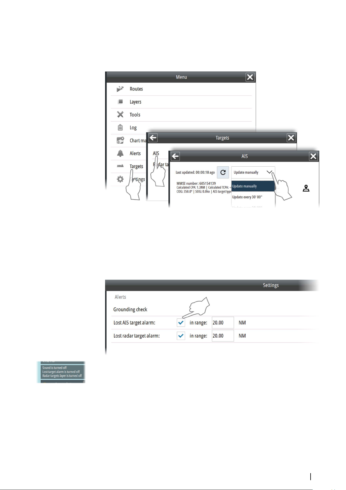
Target update frequency
The update frequency for AIS targets and Radar targets is defined in the Targets menus. The
frequency is set individually for AIS and Radar targets. From within these menus you can also
select to manually update the target information.
Lost target warnings
A warning is automatically triggered if an AIS target or Radar target is lost.
By default a lost target warning filter is enabled for both AIS and Radar targets. The filter will,
if enabled, only generate warnings for lost targets within a specified range. The filter is
intended to minimize the number of alerts presented to the user while still following general
guidelines for safety. The filter can be disabled by unchecking the checkbox. Settings for AIS
and Radar targets can be configured independently.
If any of the lost target warnings are turned off this will be indicated in the Indication panel.
Other vessels on the chart panel | E50xx ECDIS Operator Manual
45
Page 46
8
Route planning
Routes may be planned independent of the actual vessel position. The routes may be stored
and recalled whenever necessary. There are no limitations to the number of waypoints in a
route that can be stored in the system.
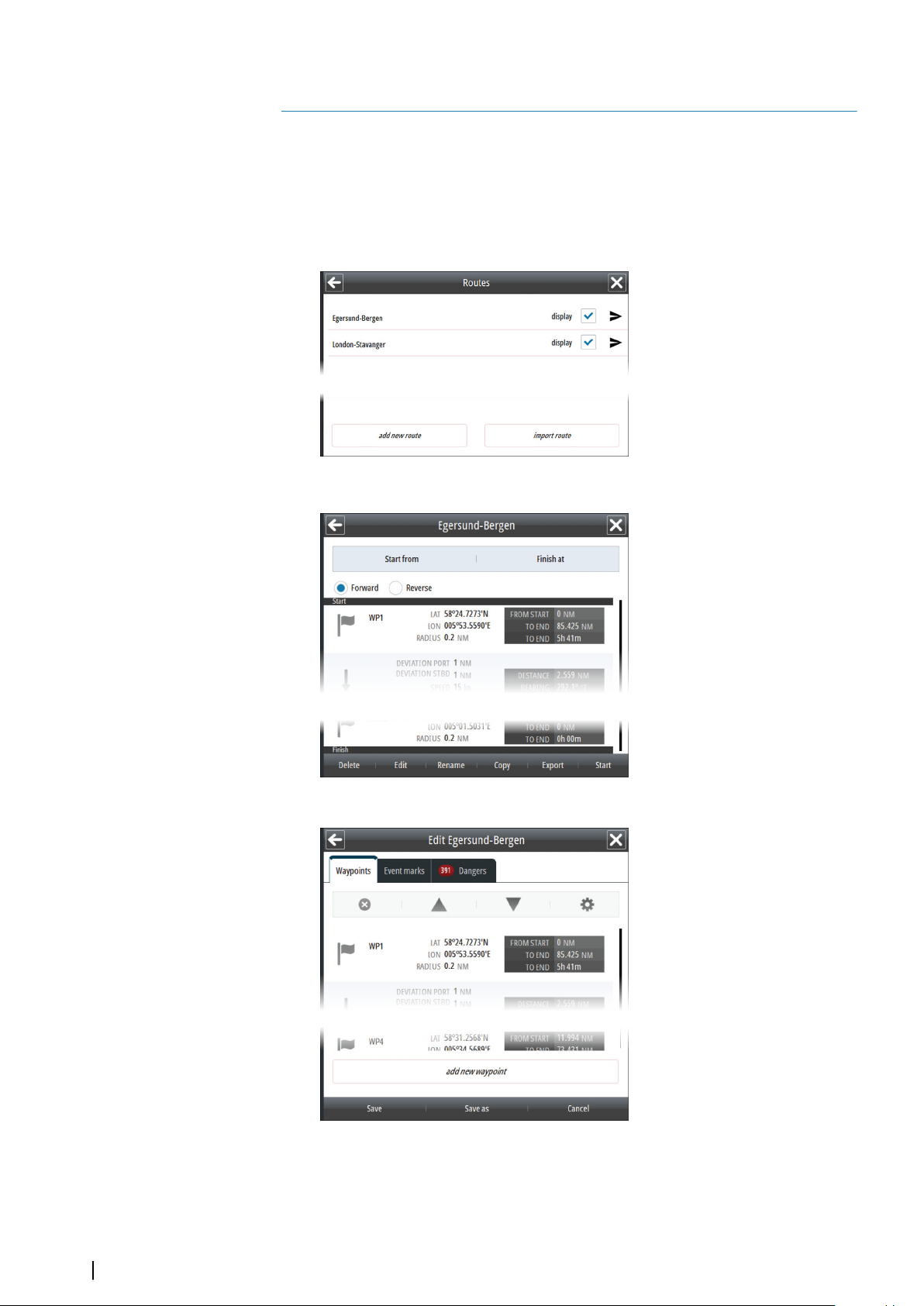
The route menus
Routes are managed by using the following menus:
The Route list, displayed by
selecting the Routes option
in the main menu.
The Routes list displays all
saved routes in the system.
From this list you can select
which routes to display and
edit, add new routes, transfer
routes to other ECDIS
systems, or import routes
from other ECDIS systems.
The Route Details menu,
displayed when you save a
route or when you select a
route in the Route list.
The Route details menu
shows details for all
waypoints and legs in a
route.
This menu includes options
for reversing, deleting,
editing, renaming, copying,
exporting and start
navigating a route.
46
The Route Edit menu,
displayed when you start
creating a new route or
when you select the Edit
option in the Route Details
menu.
The menu includes options
for adding new waypoints,
editing waypoint and leg
details, re-ordering the
waypoints, adding event
marks, and for displaying
dangers in the route.
Route planning | E50xx ECDIS Operator Manual
Page 47
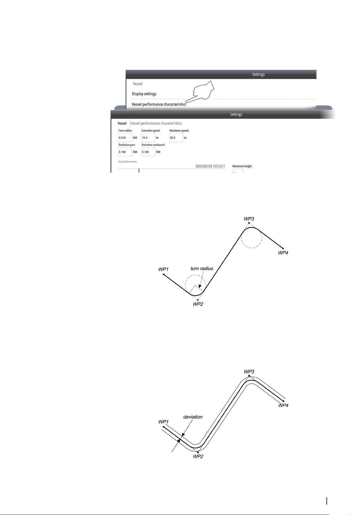
Route settings
When a new route is created or when a waypoint is added to a route, the system will use the
vessel's performance characteristics defined in the Vessel settings.
The route settings may be set individually when creating or editing a route.
• Turn radius: Each waypoint in a route, except the first and the last, has an associated turn
radius defined. This turn radius will make the ship turn over before the waypoint is
reached.
• Economic speed: Used for calculating estimated time of arrival (ETA). During route
navigation Current speed is used for calculating ETA.
• Maximum speed: Defines the vessel's maximum speed.
• Deviation: Defines the vessel’s offset distance from leg before an alert is given. The
caution and dangerous objects (in the Dangers tab) are also determined by this
parameter.
Route planning | E50xx ECDIS Operator Manual
47
Page 48

Creating a new route
Two methods may be used when creating a new route:
• Plotting the waypoints in the chart
• Manually enter waypoints into the Route Edit dialog
Plotting waypoints is used when a rough position of the waypoints is sufficient, while the
waypoint’s coordinates may be exactly defined in the dialog. Generally, a combination of
these two methods may be the best.
1. Start creating a new route by selecting the New route shortcut button, by selecting the
New route option from the panel menu activated by right-clicking in the chart panel, or
by selecting the Add new route option in the Routes list
2. Enter the new route name, and confirm your selection
-
The Route Edit dialog is displayed
3. Move the cursor to the position of the first waypoint, and press the left cursor key
- The waypoint with waypoint number is positioned on the chart and waypoint details
are shown in the Route Edit dialog
4. Continue entering new waypoints by moving the cursor to new positions and pressing
the left cursor key
5. Save the route by selecting the Save button in the Route Edit dialog
- The Route Edit dialog is replaced with the Route Details dialog
If it should be required to move the chart while using the cursor for planning a route, the
chart can be panned to selected position.
Displaying a route
You display a route in the chart by selecting the Display option in the Routes list.
48
Route planning | E50xx ECDIS Operator Manual
Page 49
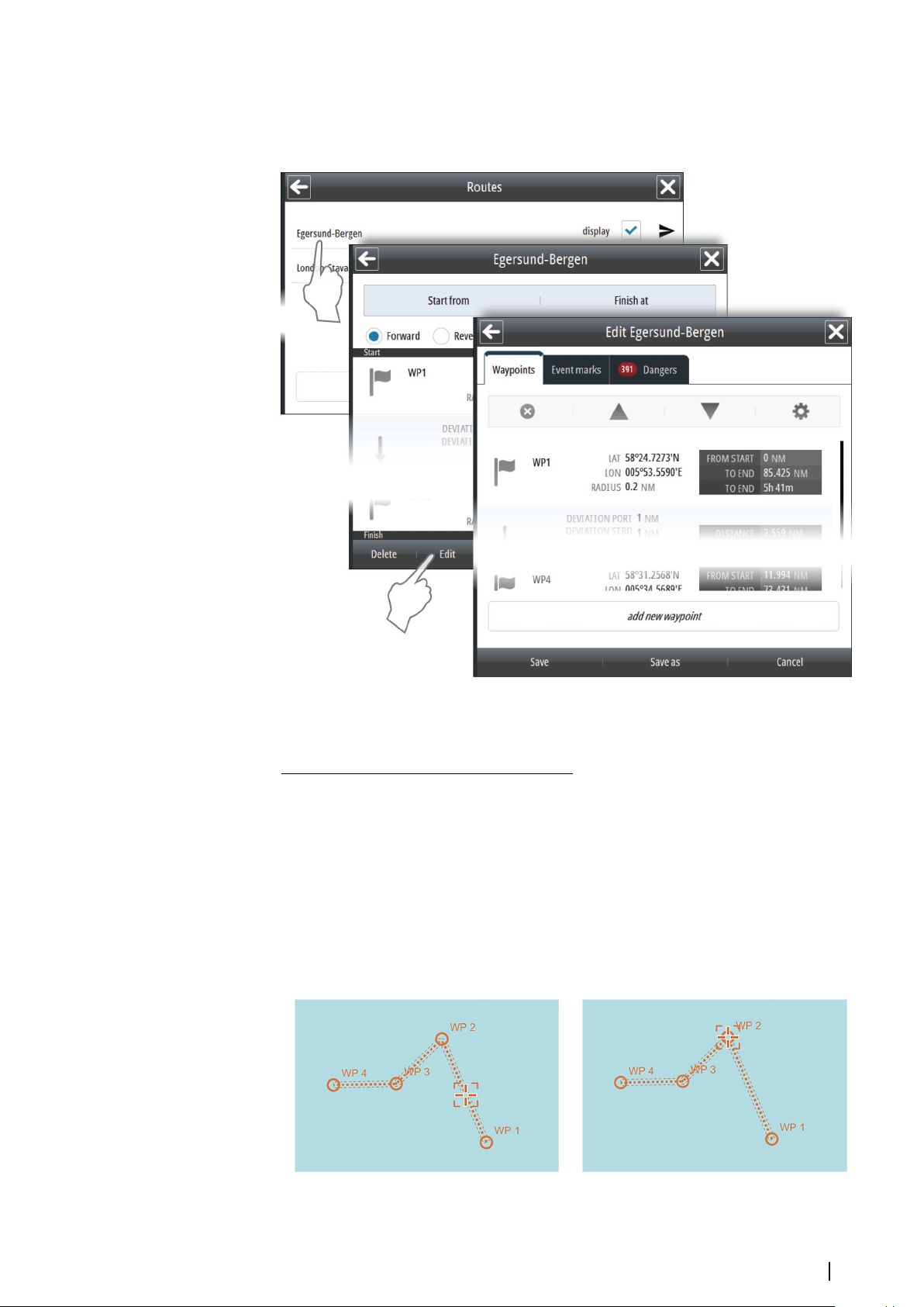
Modifying routes
Some parameters in a route may be modified from the Route dialog when the route is
created or after the route has been saved.
Note: You need to select the Edit button to turn a saved route into edit mode.
Ú
Adding and moving waypoints
To add or move a waypoint by using the cursor
1. Move the cursor to the waypoint you want to move or to the leg where you want to
insert a new waypoint
-
A dotted square is displayed under the cursor to indicate edit mode
2. To add a new waypoint: press the left cursor key on the leg where you want to position a
new waypoint
Note: The new waypoint is added as the last waypoint in the route if the cursor is not
Ú
positioned on a leg when you press the left cursor key.
3. To move a waypoint: press the left cursor button on the waypoint to unfix it, move the
cursor to the new position, then repress the left cursor button to fix the waypoint to the
new position
New waypoint to be created on leg Movable waypoint
Route planning | E50xx ECDIS Operator Manual
49
Page 50
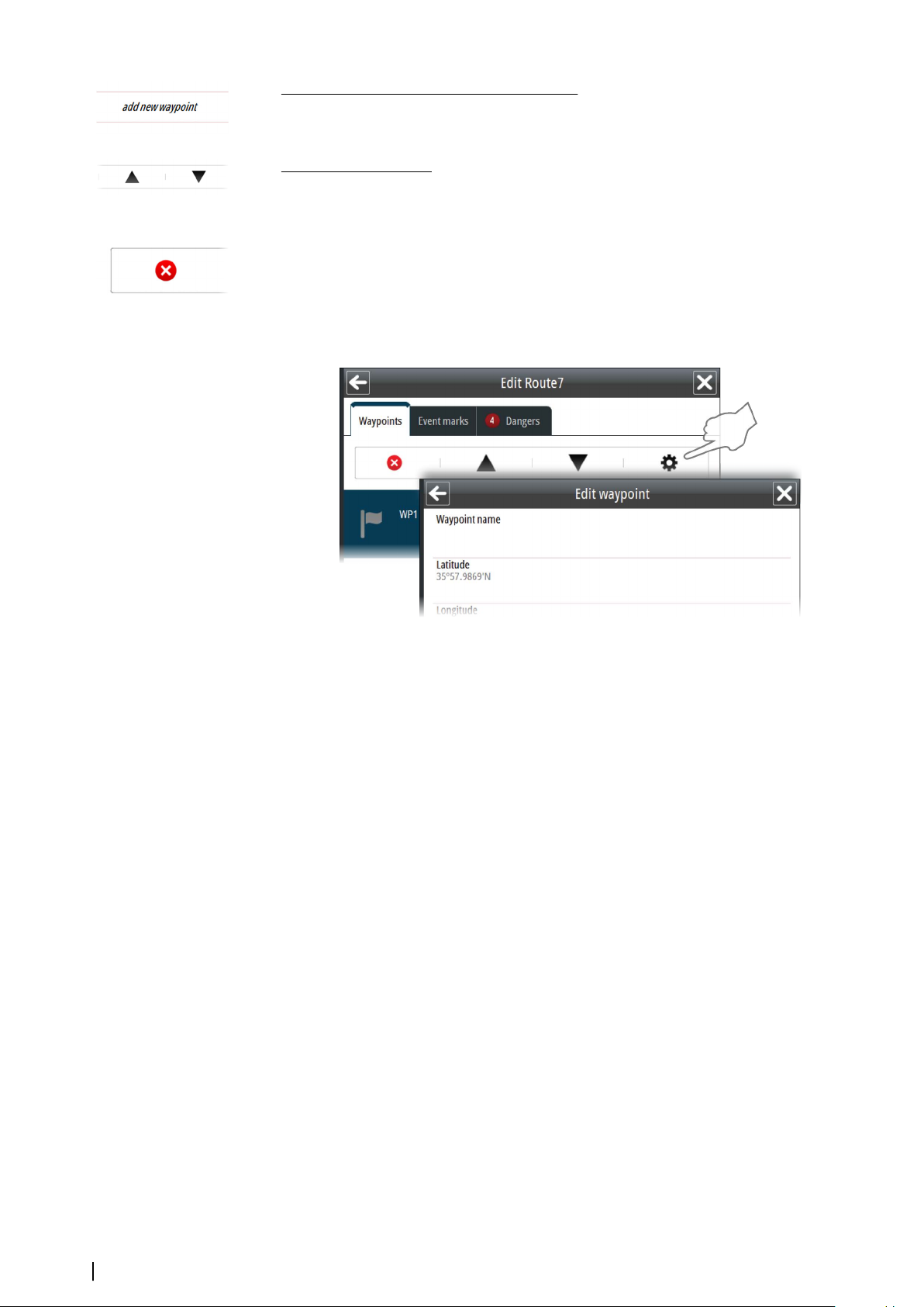
To add a new waypoint by entering coordinates
Select the Add new waypoint option in the Route Edit dialog.
Note: Using this option you can only add a waypoint to the end of the route.
Ú
To re-arrange waypoints
Use the arrow keys in the Route Edit dialog.
Deleting a waypoint
A waypoint is deleted by selecting the Delete icon in the Route Edit dialog.
When confirmed the waypoint is deleted from the list of waypoints and from the chart view.
Edit waypoint details
You edit waypoint details from the Route Edit dialog.
Reversing a route
A route may be reversed by selecting the Reverse option key in the Route window. The
waypoints will immediately be shown in reversed order in the Waypoint table, and will be reordered in the chart view when you start the voyage.
Note: The reversing is a navigational setting to a route, and the renumbering of
Ú
waypoints will not be saved as a permanent modification to the route.
Adding an event mark
You can add event marks to a route to inform about an event that is planned to happen.
A warning will be triggered within the specified time or distance before the event mark is
reached.
You can add an event mark when a route is created or when a route is modified.
1. Select the Event Marks tab in the Waypoint list
2. Select the Add new event mark button
-
A new event mark will be positioned in the center of the chart panel, and the Edit
event mark dialog is displayed
3. Enter details for the event mark, including warning time as either time or distance to the
event. If you enter a description for the event this text will be displayed in the navigation
panel when the event is triggered.
4. If required, move the cursor to the event mark to activate it, then drag it to a new position.
Confirm the new position by pressing the left cursor key
5. Save your changes to leave the route's edit mode and to return to the route's list of
waypoints
50
Route planning | E50xx ECDIS Operator Manual
Page 51
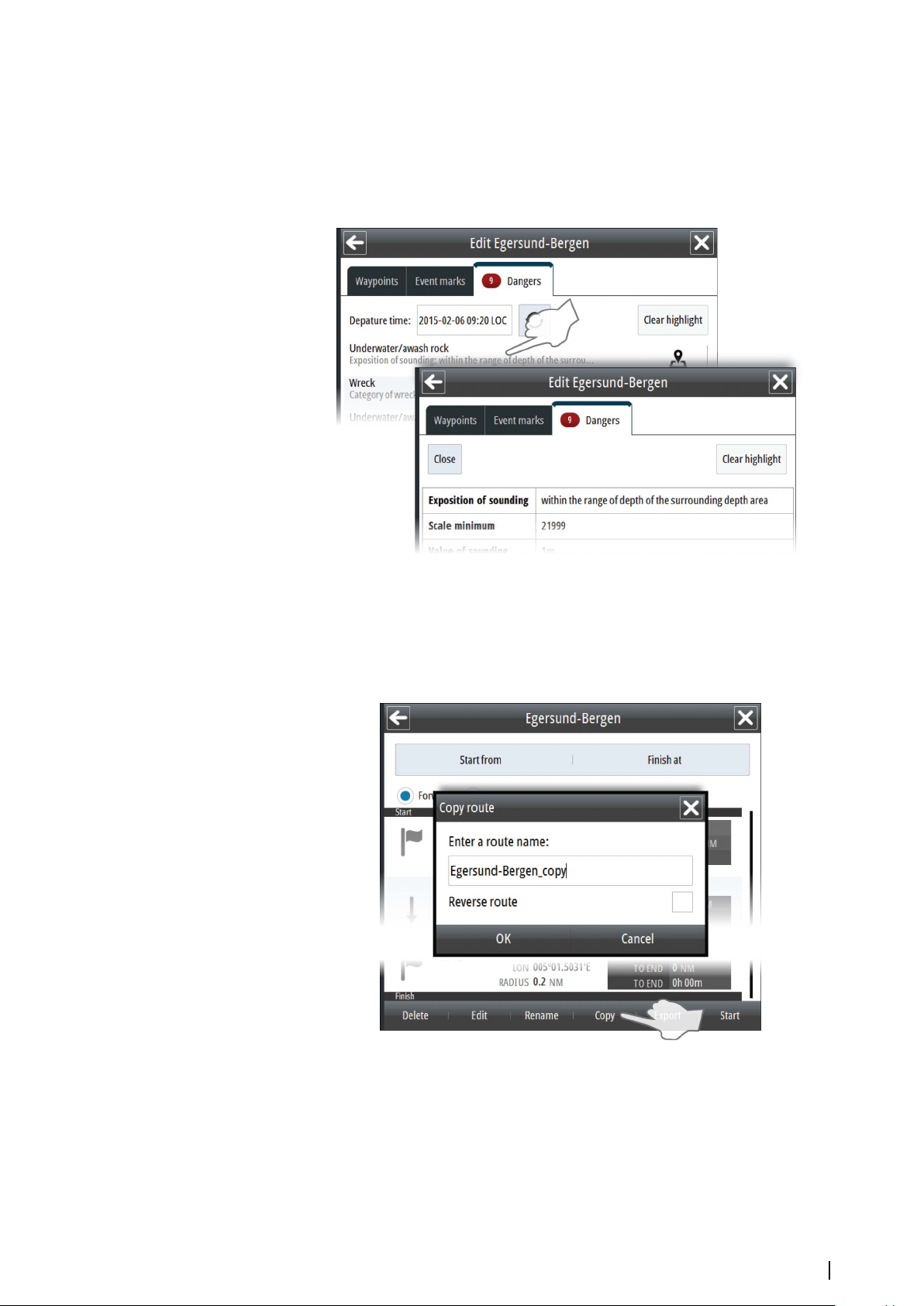
Displaying information about danger objects in a route
The system will automatically check for danger and caution objects when you create a route
or when you open a route for modification.
The list of all danger and caution objects in a route is displayed in the Routes dialog.
You display details about an object by selecting it.
Copying a route
You copy a route from the Route Details dialog.
Select the route you want to copy, enter a route name and whether you want to reverse the
route.
When confirmed the route is copied to the Route list.
Note: This feature creates a copy of the route in the system. See also "Exporting routes" on
Ú
page 52
Route planning | E50xx ECDIS Operator Manual
51
Page 52
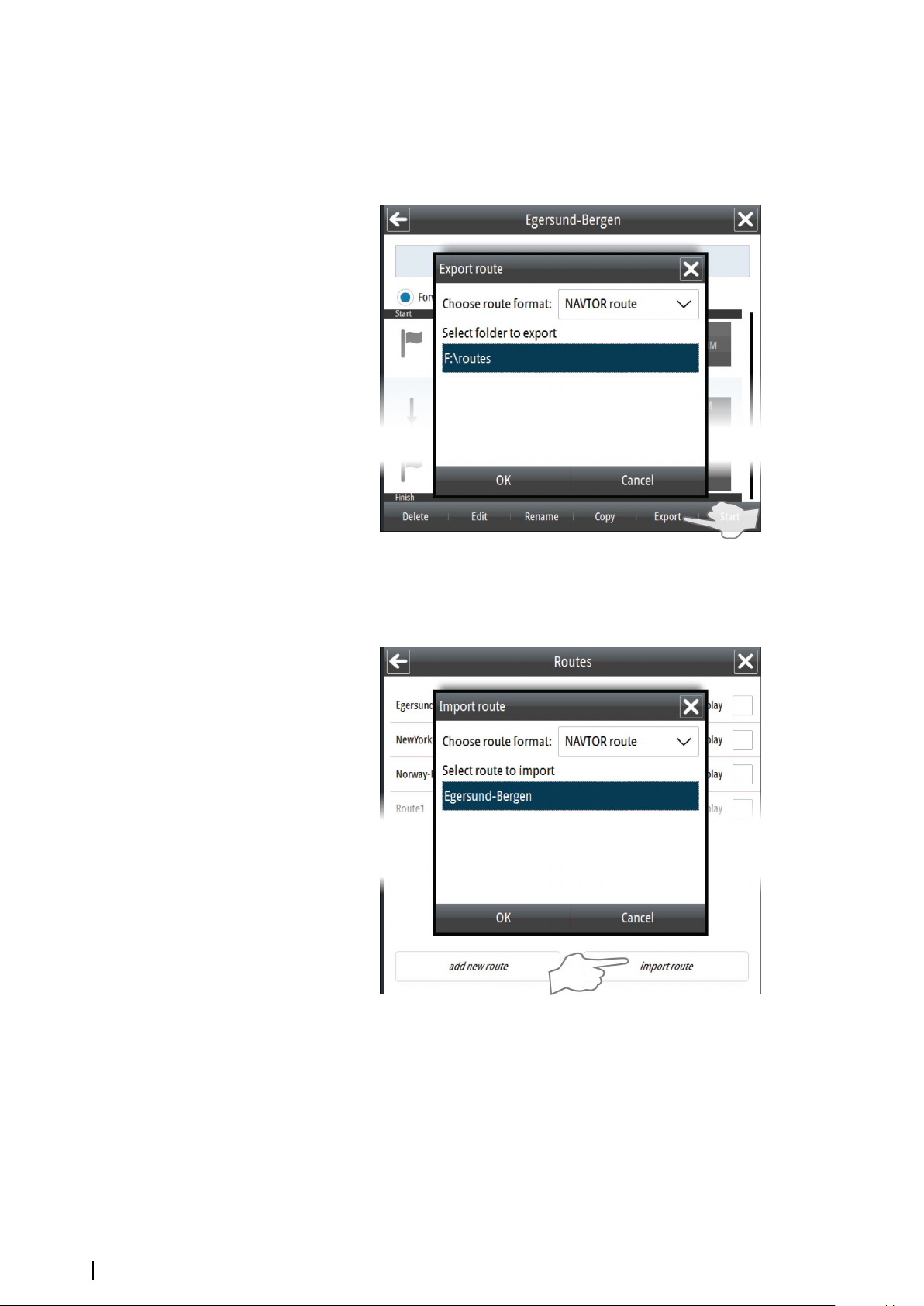
Exporting routes
You export a route to an SD card or to a USB drive from the Route Details dialog.
When format is confirmed the route is copied to the selected media. The exported route
name will be identical to the original route name.
Importing routes
You can import routes from an SD card or from an USB drive.
When the route is confirmed the route is copied to the system and listed in the Routes list.
52
Note: Only routes stored on the root level or in the "routes" folder of the device will be
Ú
found.
Route planning | E50xx ECDIS Operator Manual
Page 53

Transferring routes
You can transfer (send) routes to another unit on the network. Select the Transfer route icon
next to the route to send it to the destination unit. For destination unit ID information refer to
the E50xx ECDIS Installation manual.
When a route is transferred, the destination unit receives a message that a route transfer
needs acceptance or rejection. When the route transfer is accepted or rejected, the sending
unit receives a message that the route transfer is accepted or rejected by the destination
unit.
You can see the status of the transfer by selecting the Route transfer status option in the
Tools dialog. You open the Tools dialog from the main menu.
Route planning | E50xx ECDIS Operator Manual
53
Page 54
9
Sailing along a predefined route
The Route function in the ECDIS system makes it possible to sail along any preplanned route.
The system will give an alert if the vessel’s heading or position differs from predefined values
defined when the route was planned. The system will also give a wheel over warning before
a planned turn.
• The SOLAS convention requires that all charts must be updated for intended voyages.
Before planning or editing a route it is required to receive the latest chart updates. Refer to
"Installing charts" on page 20.
When the Route function is started, the Navigation panel is activated to show current voyage
information.
Starting a voyage
A voyage is started by selecting the Start button in the Route dialog.
When the route is started, the following changes appear:
• The route is labelled as Active in the route dialog
• The Navigation panel is displayed, showing route information
• The Stop Route shortcut button becomes available
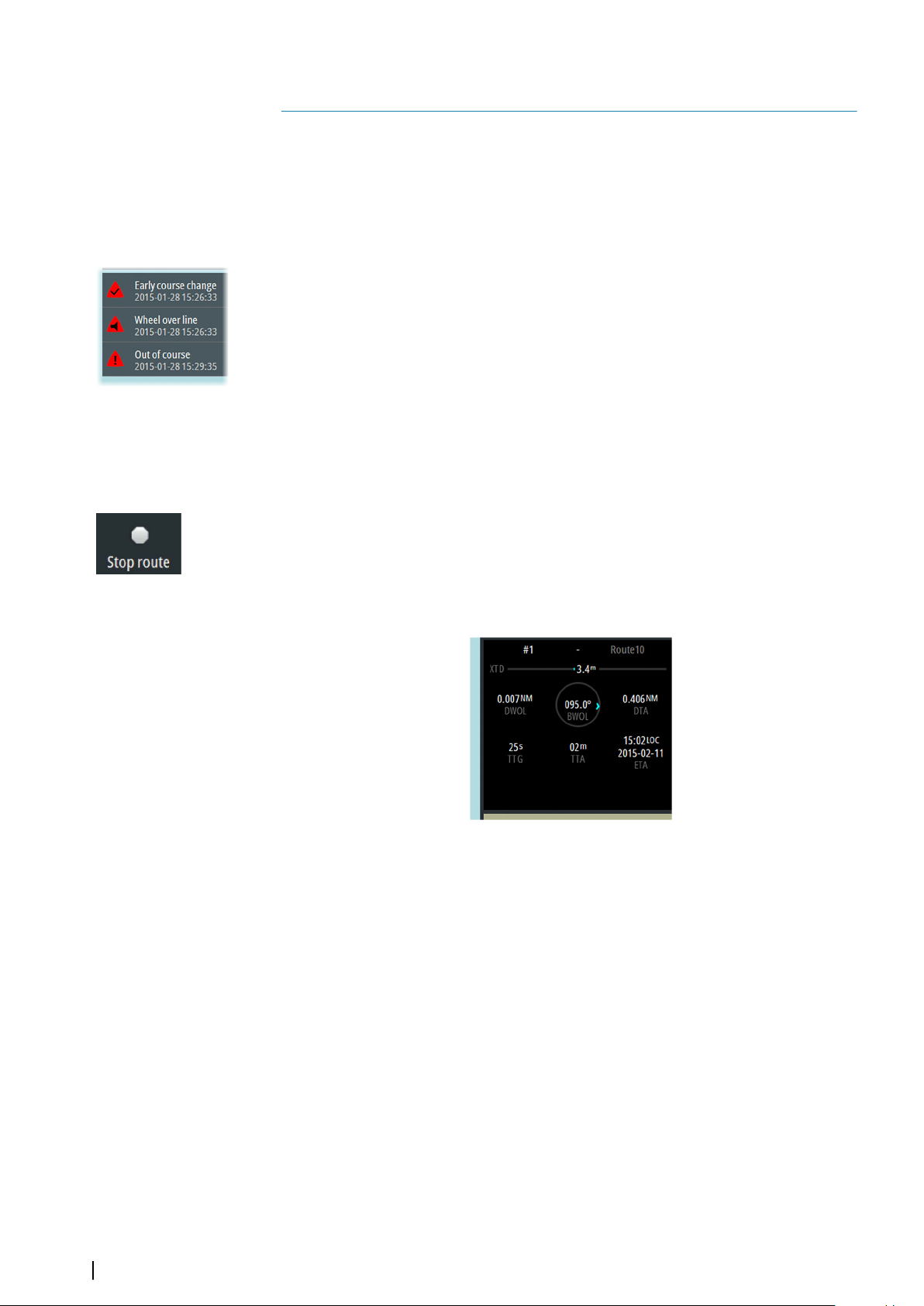
Stopping the voyage
An active voyage is stopped by selecting the Stop route shortcut button. The voyage can
also be stopped from within the Route dialog.
The Navigation panel
The Navigation panel is automatically activated when you start navigating a route.
The upper part of the panel displays active waypoint number and route name. The following
additional information is available:
• XTD: Cross Track Distance. Blue color indicates that the vessel is within the allowed
deviation for the active leg. If the vessel's distance from track exceeds the allowed
deviation the color indication turns red.
• DWOL: Distance from the current position to the next wheel-over line
• BWOL: Bearing from the current position to the next wheel-over line
• DTA: Distance from the current position to last waypoint in the route
• TTG: Time to go from the current position to the next wheel-over line using the vessel’s
current speed
• TTA: Time to go from the current position to the end of the route. The time is calculated
by using the vessel’s current speed until next wheel over point, then using the route's
planned speed for the remaining legs
• ETA: Estimated time and date of arrival at the last waypoint
54
Sailing along a predefined route | E50xx ECDIS Operator Manual
Page 55

10
Managing the chart database
The charts are managed from the Chart management option in the main menu.
Note: The system must use authorized charts to be ECDIS approved. When not using an
Ú
official chart, this will be indicated with text in the Indication panel.
The Chart database
The system is designed for using approved ENC charts in S57 or S63 formats.
A word-wide overview chart is pre-installed in the system. During installation and setup of
the system the required and detailed charts must be installed.
For details about chart installation procedure, refer to "Installing charts" on page 20.
Displaying chart information
The currently displayed chart cell and scale is displayed in the Chart information panel.
The official authority’s summary report for the active chart is displayed from the object
information menu, activated by right-clicking anywhere in the chart.
Managing the chart database | E50xx ECDIS Operator Manual
55
Page 56
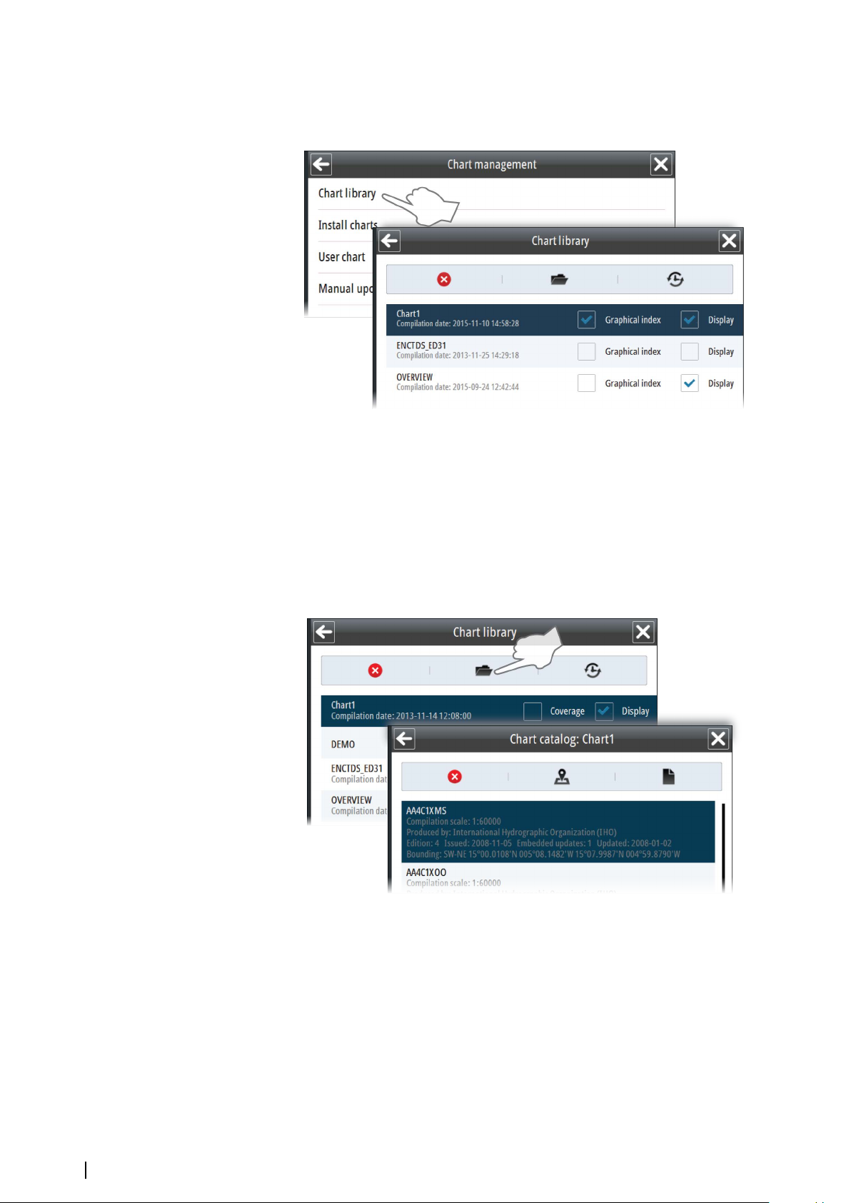
The Chart library
All Chart databases installed in the system are listed in the Chart Library.
From the chart library you can delete a chart database, access the chart catalog for a selected
database, and display the history for a selected chart database.
Chart catalogs
The Chart catalogs lists all datasets included in a chart database with detailed information
about the charts.
From the list you can delete a dataset, display the dataset, and display a text file with
additional information if this is available.
You can also search or filter chart cells by name.
56
Managing the chart database | E50xx ECDIS Operator Manual
Page 57
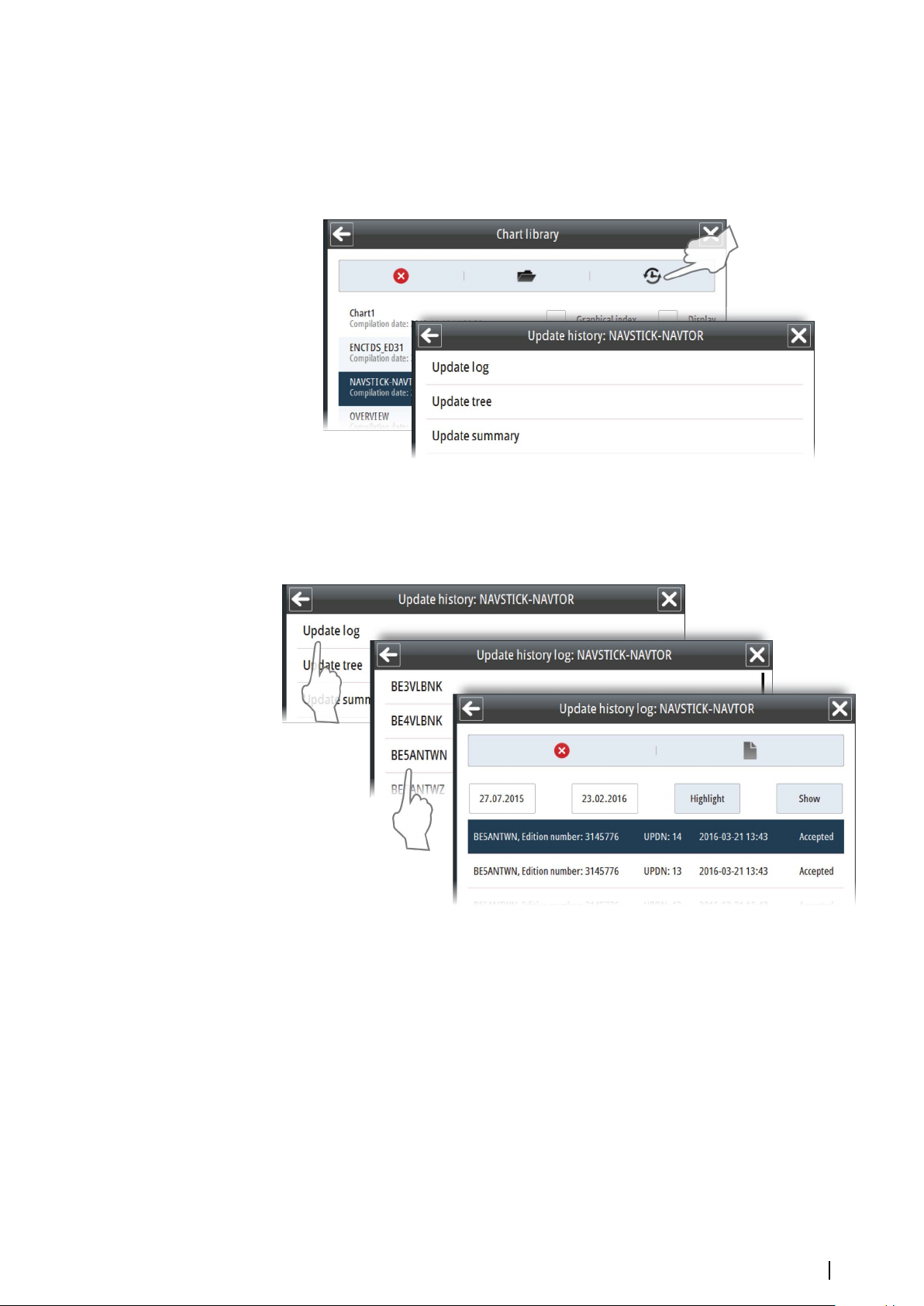
Viewing the chart update history
You can view all updates added to a database. You can show historical updates on the chart
panel with highlights. You can also show history as an update tree with detailed information
about each updated object sorted by agency or issue date or as a summary with brief
information.
Showing updates on chart panel
Select a log and then the Show button to display the log on the chart panel. Select Highlight
to highlight changes on the chart.
Managing the chart database | E50xx ECDIS Operator Manual
57
Page 58

Manual chart updates
You can manually edit a dataset by adding new objects and modify existing objects by using
the Manual update function.
Note: The Manual update option is only to be used for official chart updates. Other chart
Ú
information can be added to the chart by using the User chart function. Refer to "User
chart objects" on page 58.
Adding a Manual update
1. Move the chart to show the area where you want to position the new object
2. Right-click on the chart and select Chart info to display the name of the chart cell where
you want to add the new object
3. Select the Add object in the Manual update menu
-
A list of chart cells available for the current chart view is displayed. This list includes all
chart cells for the shown area, also those not displayed
4. Select the chart cell to which you want to add the new object
- The chart view is moved and scaled to show the selected chart cell and the coverage
for this
- A list of object categories is displayed in the menu area
5. Select a category and then the type of object you want to add
- The selected object type is displayed in the menu area
6. Select the geometry icon to display option for shape and position
7. Position the object by either entering the coordinates manually or by positioning the
cursor in the chart
8. Continue entering new positions if the object shape is an area or a line
9. Select the Apply button to confirm the object shape and position
10. Edit details for the object if required by using the Settings icon, eventually add child
objects by using the Child icon
11. Select the Save button to save the object
The object is now saved to the selected chart cell.
58
Note: When selecting a chart cell, the chart view is moved and scaled to display the
Ú
selected chart cell and it's coverage. It is not allowed to plot or edit an object outside the
selected chart cell.
User chart objects
You can plot your own markers or areas to identify events, hazards, mariner objects, etc. in
the chart. User chart objects are not saved to a specific chart dataset, but to a separate layer
that can be turned on and off.
Managing the chart database | E50xx ECDIS Operator Manual
Page 59

Adding user chart objects
User chart objects are added by using the User chart option in the Chart management
menu.
1. Select the Add object in the User chart menu
-
A list of object categories is displayed in the menu area
2. Select a category and then the type of object you want to add
- The selected object type is displayed in the menu area
3. Select the geometry icon to display option for shape and position
4. Position the object by either entering the coordinates manually or by positioning the
cursor in the chart
5. Continue entering new positions if the object shape is an area or a line
6. Select the Apply button to confirm the object shape and position
7. Edit details for the object if required by using the Settings icon, eventually add child
objects by using the Child icon
8. Select the Save button to save the object
You can quickly place Mariner objects from the Panel menu. This option has only a few
Mariner object categories available. You also need to use the geometry dialog to position the
object, as you do when you add mariner objects from the main menu.
Managing the chart database | E50xx ECDIS Operator Manual
59
Page 60
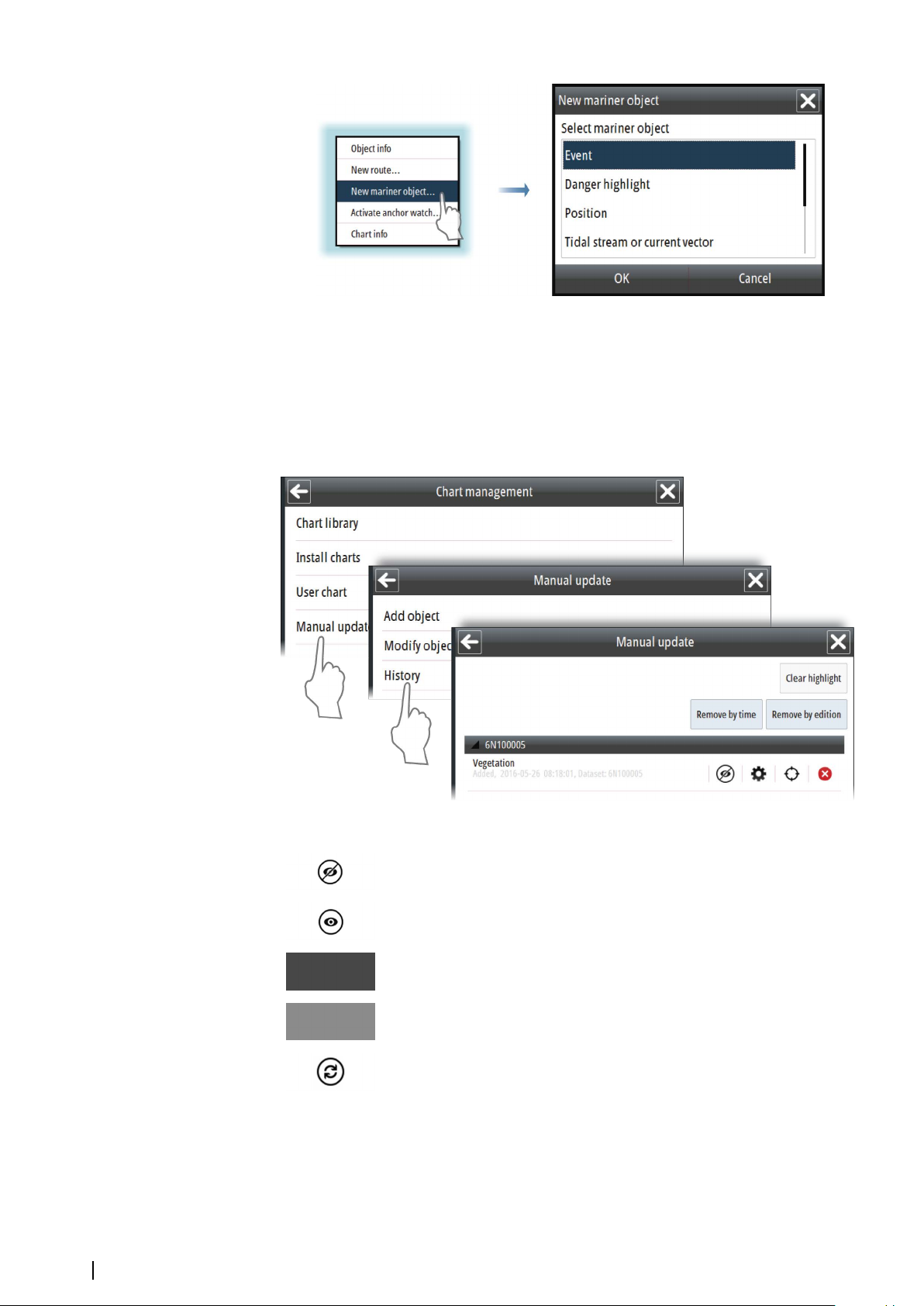
Manual updates and User chart objects update history
The History option for Manual updates and User chart (including Mariner objects) in the
Chart management menu includes a list of all changes. The history options also allows for
editing item details.
The example shows the Manual update history menu.
60
The following options are available:
Hide item
Show item
Edit item details
Move chart to display item in center of the chart panel
Refresh the list of items
Managing the chart database | E50xx ECDIS Operator Manual
Page 61
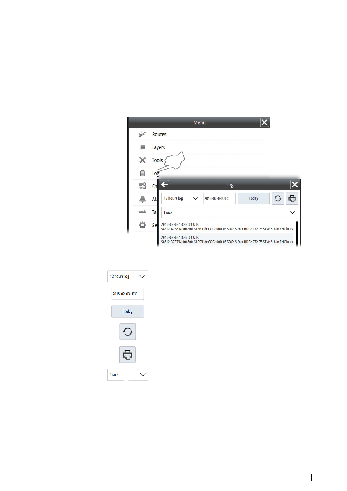
11
The Log book
System information and vessel movements are automatically logged and saved to an internal
database in the system.
Two log books are recorded at the same time: the 12-hour log book where records are done
at 1 minute intervals, and the 3-month log book where records are done at 15 minute
intervals.
Note: Records of the 12-hour log book are available two days back from the current
Ú
date. Records of the 3-month log book are available 90 days back from the current date.
The Log book is accessed from the Main menu.
The following options are available:
Drop-down list for switching between the 12-hours log book and the 3months log book.
Field for entering a specific date for the log
Displays today's log
Refreshes the log
Opens the logs to be converted to pdf format and copied to a
removable media.
Drop-down list for selecting log type
The Log book | E50xx ECDIS Operator Manual
61
Page 62

12
PLECDIS systems
A Simrad PLECDISTM system consists of two identical type approved E5024 or E5027 ECDIS
systems via the Ethernet ports on the E5000 processor. When type approved charts are used
in the system, a PLECDIS system allows the ship to operate without paper charts onboard.
A PLECDIS system can be set up to automatically synchronize chart database, mariner
objects, routes, permits and configuration between all connected E5000 processors. The
backup system ensures that a system failure does not result in a critical situation, and
provides safe navigation for the remaining part of the voyage in case of failure in the primary
ECDIS system.
Defining main and backup ECDIS systems
Main and back-up systems are recognized by the systems' name and IP address.
The main system has to be labeled ECDIS 1. This is the default settings for all E5024 and
E5027 systems when delivered from factory. The second system can have any number to
identify it as backup system.
You change the name of the system from the System Information dialog.
62
PLECDIS systems | E50xx ECDIS Operator Manual
Page 63

Automatic data synchronization
When two systems are interconnected, the system can be set up to automatically
synchronize data between the systems.
This setting is done in the System Synchronization dialog.
1. Double-click the Node name field
-
The system will automatically assume a name for the first ECDIS that are to be included
in the synchronization setup
2. Re-name the node's system name if required
3. Enter the node's IP address
4. Tick the Automatic backup field if the system should be included in the automatic backup
5. Confirm and save the configuration by selecting the Apply button.
Any changes to manual updates, mariner objects, routes, data permits, and configuration
files will now automatically be synchronized between the ECDIS systems included in the
synchronization setup.
PLECDIS systems | E50xx ECDIS Operator Manual
63
Page 64

Manual data synchronization
You can manually back up data on one ECDIS system with other interconnected ECDIS
systems. The back up can include the chart database with manual updates, mariner objects,
routes, data permits, and configuration files. The manual update is started from the Backup
arrangement dialog.
Select the Synchronize option to start the backup process. The status indication will change
from Idle to Uploading on the ECDIS sending the data, and to Downloading on the receiving
ECDIS.
Note: During backup both the sending and the receiving ECDIS system must be
Ú
running. Data that are being updated on the receiving ECDIS are not available for use.
64
PLECDIS systems | E50xx ECDIS Operator Manual
Page 65

Maintenance
13
Maintenance philosophy
All units in the system are “repair by replacement” units, and the operator is therefore
required to perform only a very limited amount of preventive maintenance.
Checking the connectors
The connectors should be checked by visual inspection only.
Push the connector plugs into the connector. If the connector plugs are equipped with a
lock, ensure that it is in the correct position.
Verifying the display color
The system includes a color test area to enable the user to detect the stage at which the
display can no longer be used to discriminate important features by color.
1. Open the Chart library panel
2. Open the chart catalog for the Chart1 database
3. Select the Display Object icon for the AA5C1WOO dataset
-
The display moves and scales the chart to 1:14 000. This scale should not be changed
4. Verify that the color for the diagonal lines can be clearly distinguished from the
background. If not, the monitor has to be sent to Simrad for recalibration
5. Return to the Chart library panel and select your preferred chart database to go back to
normal operation
Maintenance| E50xx ECDIS Operator Manual
65
Page 66

Backup and restore of system data
The system includes a backup and restore function, making it possible to back-up and
restore local system data.
Note: This is not a backup of the full system image, merely the configuration and
Ú
settings. For route back-up, each route has to be exported to external storage or another
ECDIS.
It is recommended to have backup routines that are carried out regularly.
Note: It is strongly recommended to make a complete system backup when the system
Ú
is installed and configured.
Backup and restore are initiated from the System Backup and restore user settings dialog.
Select Backup to external media to save your system data to an external memory device
located in the USB reader or in the SD-card reader on the E5000 unit.
Select Restore from external media to restore files from an external memory device.
Select Restore from internal storage to restore to factory settings.
Note: For back-up and synchronization between multiple ECDIS systems, refer to "PLECDIS
Ú
systems" on page 62.
Software upgrades
Software version, the SDK version and the Presentation library version are listed in the System
Information dialog.
66
The latest software is available for download from our website, www.navico.com/
commercial.
Maintenance| E50xx ECDIS Operator Manual
Page 67

Detailed instructions for how to install the software are included with the upgrade files.
Maintenance| E50xx ECDIS Operator Manual
67
Page 68

System messages
14
The ECDIS message system
The system will continuously check for danger situations and system faults while the system
is running.
In the system, the alert escalation is set to 60 seconds and users are not able to change the
alert escalation time.
There are 3 types of messages displayed in the Alerts panel:
• Alarms: This is the system's highest priority alert, activated when situation occurs that
might result in collision with other vessels, when you enter shallow water area, or for
conditions that critically effect the capability or performance of the system. You must
critically examine all alarm messages to determine their cause and effect.
Alarms are followed by an acoustic alarms. The alarm icon is flashing until the alarm is
acknowledged.
• Warnings: This is alerts of lower priority, announcing conditions that could result in
unwanted system response or eventual failure if no action is taken
Warnings are sounded with two beeps every minute while active.
-
- All warnings are repeated as warnings except the following which are repeated as
alarms:
• Early course change (timeout = 30 sec.)
• Actual course change (timeout = 30 sec.)
• Outside the anchor watch swing circle (timeout = 2 min.) which are repeated as
alarms.
• Navigational cautions: Information about danger and caution objects within the guard
zone defined for your vessel. See "Setting a guard zone around the vessel" on page 31.
Alert notifications
When an alert is triggered, the alert icon appears in the alert panel. The alerts are also added
to the Alerts list, displayed from the main menu.
Alarms trigger an audible signal unless the sound is turned off in the System Settings dialog.
Alarms and Warnings have different states:
• Active - not acknowledged
• Active - acknowledged
• Rectified - not acknowledged
When a rectified alert is acknowledged it will disappear from the alerts panel and from the
Alerts list.
Cautions are not acknowledged, and they disappear from the system when they are no
longer present. Cautions have therefore only an active state.
The table below shows alert icon and behavior depending on if the alert is active,
acknowledged or rectified.
Type Icon State Sound
Single short sound
repeated every 7
second
None
Alarm
Active - not
acknowledged
Active acknowledged
68
System messages| E50xx ECDIS Operator Manual
Rectified - not
acknowledged
None
Page 69
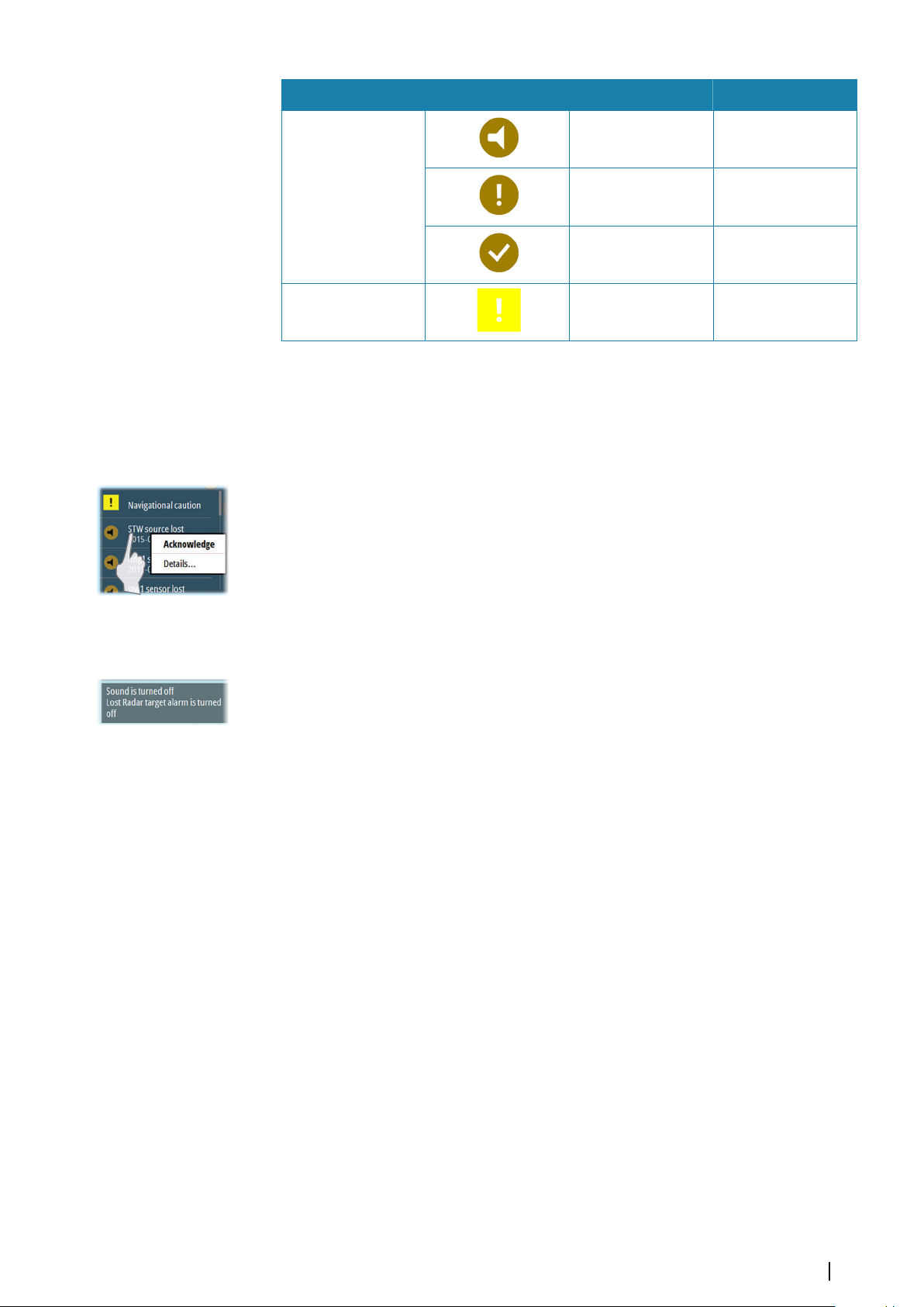
Type Icon State Sound
Active - not
acknowledged
Warning
Caution Active None
Active acknowledged
Rectified - not
acknowledged
None
None
None
Acknowledging alerts
You acknowledge an alarm or a warning by right-clicking the relevant alert in the Alert panel.
If several alerts are active they must be acknowledged separately in the Alert panel. All unacknowledged alerts can be acknowledged at the same time from the Alarms list. Refer
"Alarms list" on page 70.
When an Alarm or Warning is acknowledged, the alert icon stops flashing. For alarms the
sound is also muted.
All Alarms remain in the Alerts panel and in the Alarms list until the reason for the alarm is
removed.
Warnings are removed from the alert panel when they are acknowledged.
Indications
Indication messages inform you of conditions that are noteworthy, but that have no serious
effect on the performance of the system. No sound is triggered for indications.
All indication messages are displayed in the Indications panel. They will remain in the panel
as long as the condition remains.
Power failure alarm
By a power failure an acoustic alarm will be activated and the visual alarm on the E0102
Alarm panel will be lit.
The power failure alarm is muted by pressing the Alarm reset key on the E0102 Alarm panel.
The visual alarm in the Alarm reset key will remain lit as long as the alarm condition is
present.
If not muted, the sound and the light indication will remain until the ECDIS application is
restored to normal operation.
External bridge alert systems
The system supports Bridge Alert Management (BAM) and Bridge Navigational Watch Alarm
Systems (BNWAS).
Bridge Alert Management (BAM)
All system alerts are transferred to the bridge alert system if this is connected to the system.
An alert generated by the system - e.g. Danger target alarm - can only be acknowledged
from the system itself. Global alarms - e.g. Position timeout or Gyro failure - can be
acknowledged on both the system control unit and on the bridge alert system.
Bridge Navigational Watch Alarm Systems (BNWAS)
If a BNWAS is connected to the system, the system outputs an 'EVE' sentence to the BNWAS
when an user interaction with the system occurs. The 'EVE' sentence remotely resets the
BNWAS timer to confirm wheelhouse crew activity.
System messages| E50xx ECDIS Operator Manual
69
Page 70
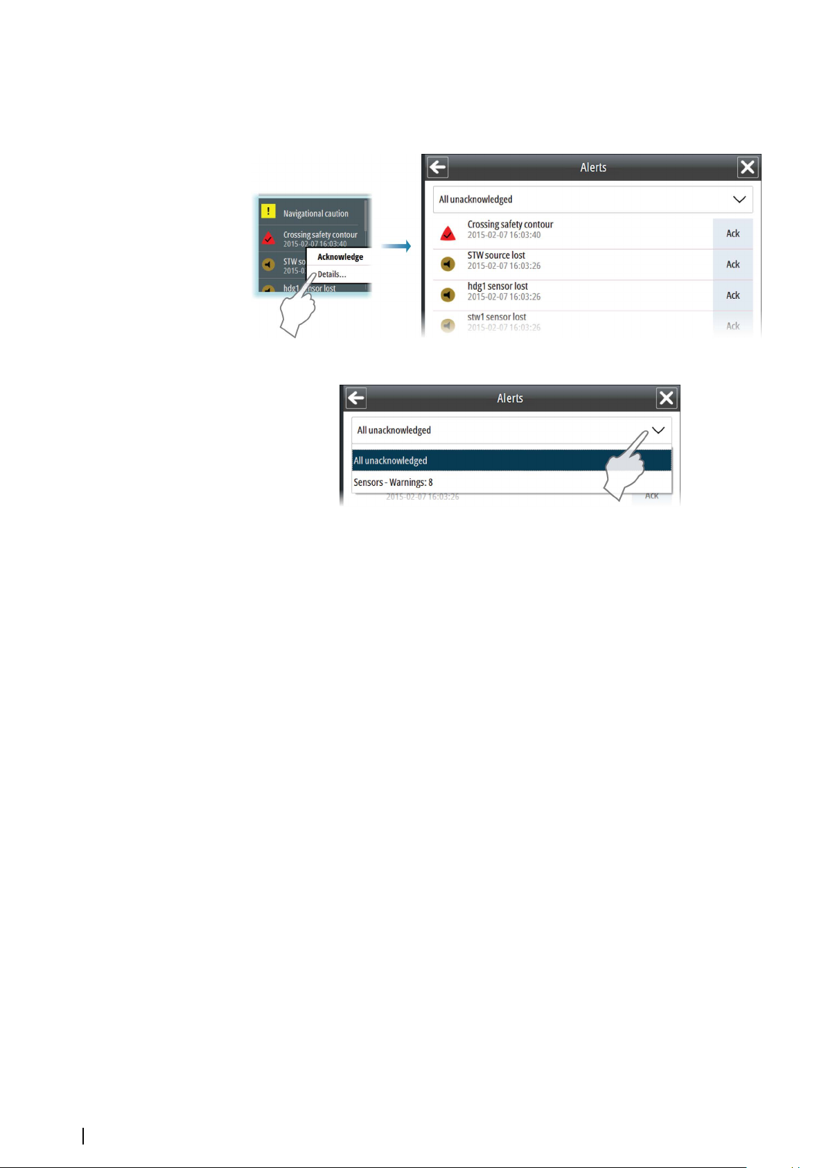
The Alerts list
You display a list of all active alarms and warnings by right-clicking an alarm or warning icon
in the Alert panel. You can also display the Alerts list from the menu.
You can list all active alerts, or you can list them by group selected from the drop-down list.
From the Alerts list you can acknowledge alerts individually or all at the same time.
70
System messages| E50xx ECDIS Operator Manual
Page 71

15
Fault finding
If an error situation has occurred, the fault is normally identified from the symptoms
observed. It is therefore important to record all these observations to help the maintenance
person or service engineer. All error messages shown on the screen should be logged for this
purpose. If you are not able to correct the error situation yourself, you should contact your
nearest Simrad service office for advice or to request service on board.
Fault identification
The fault-finding table below assumes that the problem is caused by the units included in
the system or the connected sensors, and that no other external factors are involved.
Observation Potential causes Possible solutions
• Check power cable is
properly seated and
retaining nut locked
• Ensure power source is on
and capable of providing
power
• Check fuses
Device not on – no LED
Power not plugged in or
switched on
Application not loading –
error screen, SIMRAD logo or
black screen
Monitor not on – black
screen and control panel
icons not lit
Monitor on but no image –
red LED on
Application loaded but no
charts displayed
No sensor data – sensors
indicated yellow
Corrupt file system or other
system malfunction
Power not plugged in or
switched on
HDMI not plugged in
properly
Charts not loaded/activated
or display not switched on
Sensors not switched on
• Simrad technician required
• Check power cable is
properly seated and
retaining nut locked
• Ensure power source is on
and capable of providing
power
• Check fuses
• Check HDMI plugged in
• Check HDMI cable not
working
• Refer to operation manual
to ensure charts are loaded
and display activated
• Ensure sensors are
powered on and plugged
in the CAN bus network or
the appropriate NMEA0183
ports
No sensor data – sensors
indicated yellow
Fault finding| E50xx ECDIS Operator Manual
Sensors not configured
properly
• Refer to installation manual
for sensor configuration
• Ensure baud rates are
correct where applicable
• Ensure CAN bus sensors
configured and activated
as per installation manual
71
Page 72

Observation Potential causes Possible solutions
• Ensure Audio is switched
on in settings (refer
No audible alarms
Trackball not working
PLECDIS not synchronizing
Audio off or E0102 Alarm
panel not functioning
Trackball not switched on or
battery depleted
Ethernet cable not plugged
in or configuration
operational manual)
• Ensure E0102 Alarm panel
installed as per installation
manual
• Ensure receiver plugged
into USB port on E5000
processor
• Ensure trackball unit is
switched on
• Ensure that the battery in
the trackball is not
depleted
• Ensure Ethernet cable is
plugged in properly
• Refer to installation manual
and operational manual for
PLECDIS configuration
Smoke coming out of E5000
processor unit
Unit no longer serviceable
• Unplug all cables from unit
• Simrad technician required
72
Fault finding| E50xx ECDIS Operator Manual
Page 73

16
Terms and abbreviations
AIS
Automatic Identification System. System where vessel information (location, course, speed,
etc.) is broadcast by VHF radio, for use by other vessels in navigation and collision avoidance.
ARGUS
Simrad professional X-band radar.
ARPA
Automatic Radar Plotting Aid.
ATON
Aids To Navigation.
BTW
Bearing To Waypoint. Bearing to a specified waypoint from present position. The correct
acronym for the more commonly used BPW (Bearing Position Waypoint).
BWOL
Bearing from the current position to the next wheel-over line.
CAN bus
Controller Area Network, a bus standard designed to allow microcontrollers and devices to
communicate with each other.
COG
Course Over Ground. The actual direction of progress of a vessel between two points, with
respect to the surface of the earth. The vessel’s heading may differ from the course over
ground due to the effects of wind, tide and currents.
Chart permit code
Code required to install charts on the system. The code is generated by the chart supplier
when they have received the User permit code.
CPA
Distance in Nautical miles to Closest Point of Approach for the ARPA target.
CPR
Common Reference Point.
CPU
Central Processor Unit.
DR
Dead Reckoning.
DTA
Distance from the current position to last waypoint in the route.
DWOL
Distance from the current position to the next wheel-over line.
EBL
Electronic Bearing Line.
ECDIS
Electronic Chart Display and Information System, type approved ECS system according the
ECDIS regulations.
ENC
Electronic Navigational Chart. An official database created by a national hydrographic office
for use with an Electronic Chart Display and Information System (ECDIS).
EP
Estimated Position.
Terms and abbreviations| E50xx ECDIS Operator Manual
73
Page 74

EPFS
Electronic position-fixing system.
ETA
Estimated time of arrival at the last waypoint.
GPS
Global Positioning System. A satellite based navigation tool. This system is based on satellites
in fixed orbits, circling the earth at an altitude of approximately 20,200 km. The system will
provide the user with 24 hour a day all weather position coverage, with an accuracy of 5 to
30 meters.
HDG
Heading.
IHO
International Hydrographic Organization.
IMO
International Maritime Organization.
Leg
The straight segments of a route between waypoints. A route with four waypoints has three
legs.
LOP
Line Of Position.
MFD
Multi-Function Display.
MOB
Man Over Board.
NavStick
USB drive from NAVTOR included in the system. Used for chart updates, and acts as the
bridge between the E5000 Processor and a computer with internet access.
NAVTOR
Supplier of product and services portfolio for international maritime operation. Web site:
www.navtor.com
NavTracker
A customized web interface from NAVTOR giving the navigator and ship management full
overview of chart usage, chart update history and chart management.
NavSync
PC program from NAVTOR used for receiving and updating the content on the NavStick.
NMEA
National Marine Electronics Association.
NMEA 0183
A format (language) designed to permit communication between various types of marine
electronic equipment. In essence this is a two-wire shielded, serial data link, permitting one
device to talk while other devices listen. Numerous different sentences are available,
permitting communication between various different devices.
74
NSO
Product name for a Simrad Multi-Function Display.
PLECDIS
TM
Paperless ECDIS system.
Route
A stored sequence of waypoints. These waypoints will be listed in the order in which you
desire to follow them.
Terms and abbreviations| E50xx ECDIS Operator Manual
Page 75

S57
The standard vector format for official ENC charts, stated in the International Hydrographic
Organization (IHO) Special Publication S-57.
S63
The International Hydrographic Organization standard for encrypting and securing electronic
navigational chart data.
S64
The International Hydrographic Organization test data set for chart data presentation.
SART
Search And Rescue Radar Transponder.
SI80
Signal Interface unit used for expanding the number of interface channels to the system.
Sleeping targets
Reported targets provided by the AIS can be filtered according to user-defined settings
based on range from own vessel. Targets may be sleeping, or may be activated. An AIS
“sleeping target” symbol can be visible or hidden to reduce chart clutter. Additional
information is presented when the target is activated.
SOG
Speed Over Ground. The actual speed of the vessel relative to the ocean floor.
SOLAS
SOLAS is the IMO convention to ensure Safety Of Life At Sea.
SPD
Speed.
STW
Speed Through Water
TCPA
Time in minutes to Closest Point of Approach for the ARPA target before an alarm is
activated.
TTA
Time to go from the current position to the end of the route using the route's planned
speed.
TTG
Time to go from the current position to the next wheel-over line using the route's planned
speed.
USB
Universal Serial Bus.
User permit code
A code automatically generated in the E5000 computer. This code is specific for each E5000
computer.
VRM
Variable Range Marker.
XTD
Cross Track Distance.
Terms and abbreviations| E50xx ECDIS Operator Manual
75
Page 76
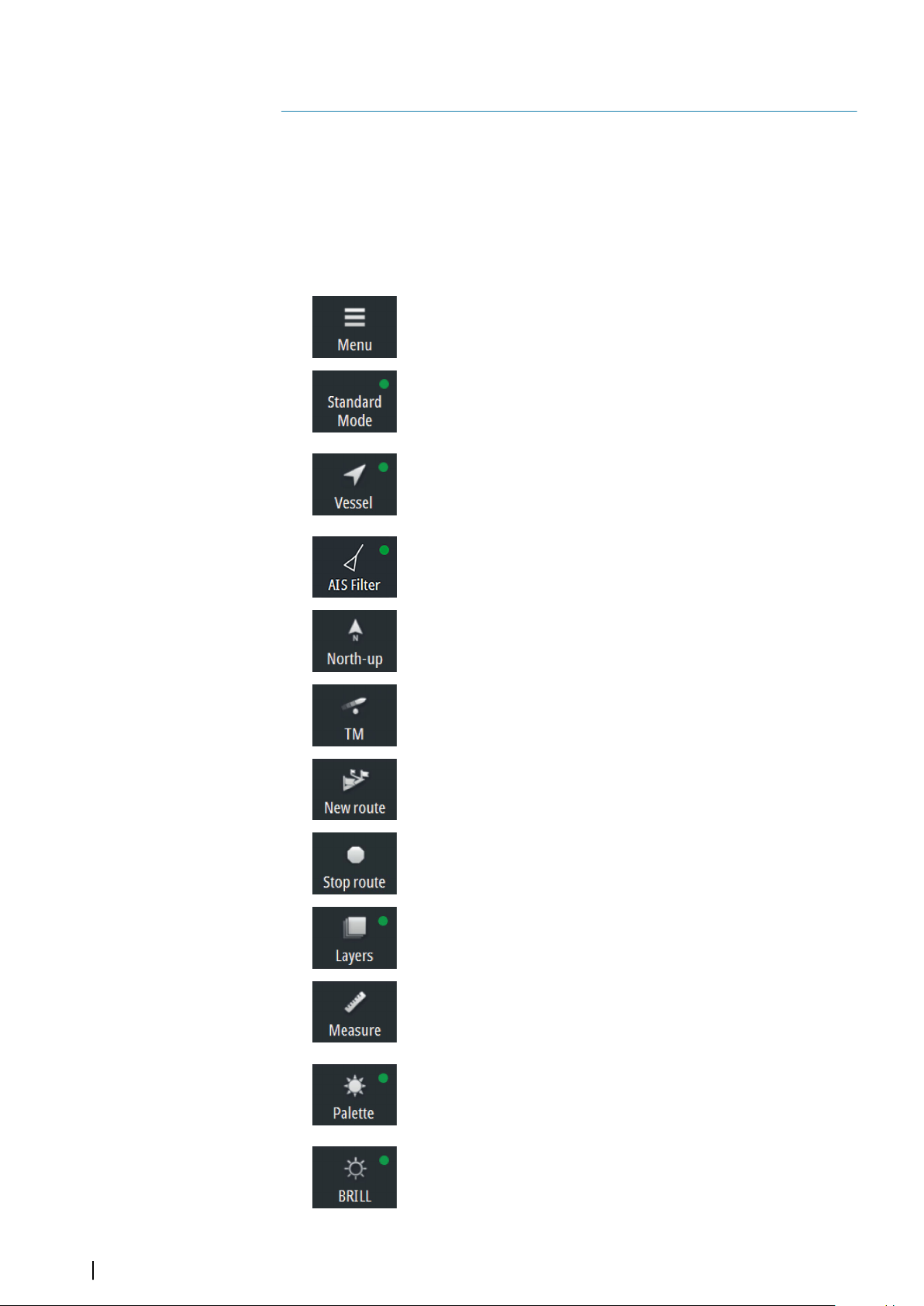
17
Icons
This section includes all icons used in the E50xx system.
If a function or an option not is available, the icon appears greyed.
Shortcut buttons
Note: Some of the shortcut buttons have a light indicator that can be green or yellow.
Ú
Green indicates standard ECDIS mode, while yellow indicates non-ECDIS mode. Oneclick on a shortcut button with a yellow indicator reverts to ECDIS mode.
Menu
• Click to open the main menu
Display mode
• Click to return to Standard mode
• Right-click to show display mode options
Follow own vessel
• Click to move the chart view to the vessel position and then
follow the vessel. Vessel position in the chart depends on user
settings
AIS Filter
• Click to turn OFF AIS filter
• Right-click to display options
Orientation
• Click to loop through chart orientation options
• Right-click to display options
Motion
• Click to toggle vessel motion options
• Right-click to display options
New route
• Click to start creating a new route
Stop route
• Click to stop navigating an active route
Layers
• Click to turn OFF all layer options
• Right-click to display options
Measure
• Click to toggle measure function on/off
Palette
• Click to return to Night palette when Red and Black palette is
selected
• Right-click to display palette options
76
Brilliance
• Click to return to calibrated brightness for the selected palette
Icons| E50xx ECDIS Operator Manual
Page 77
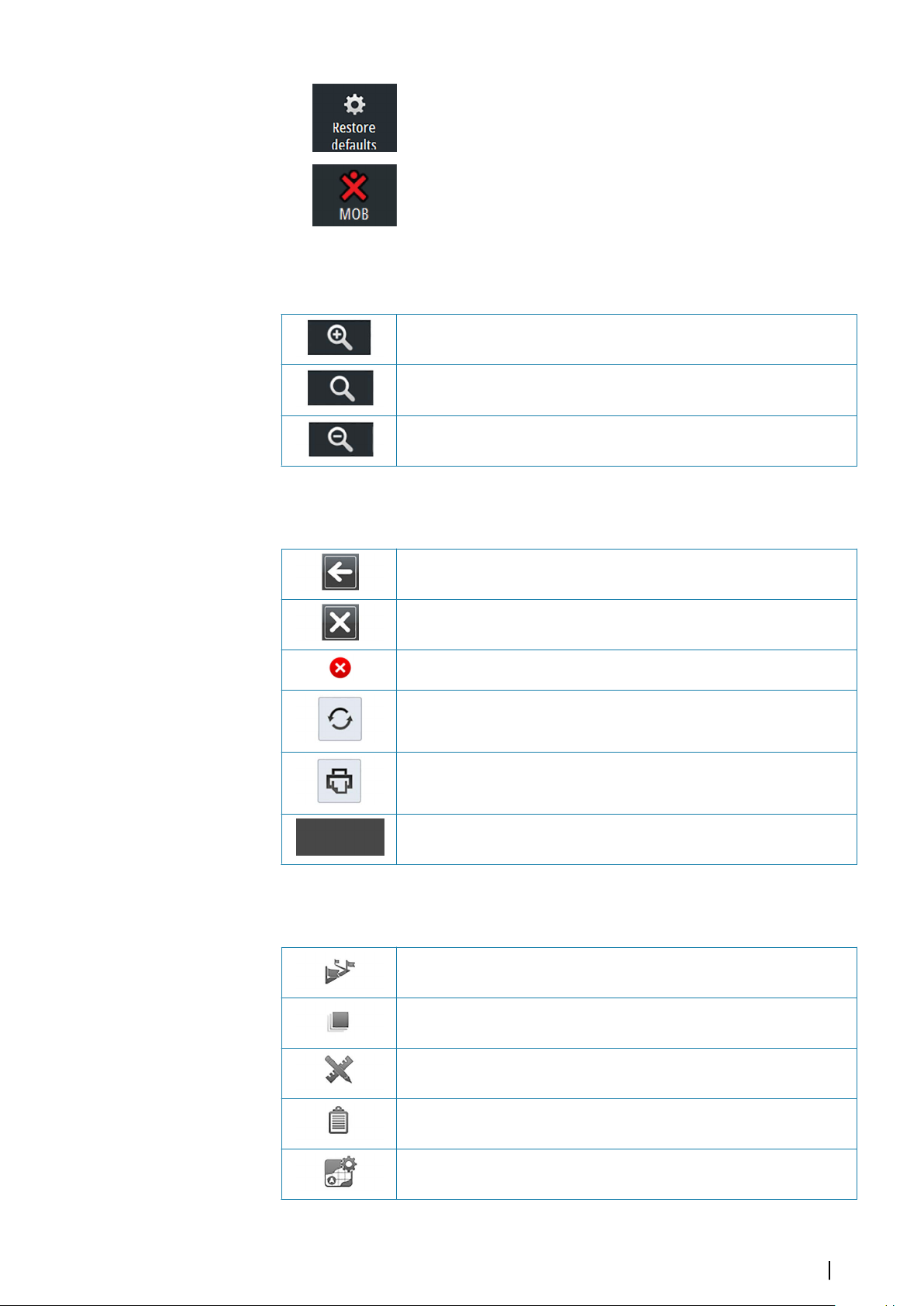
Restore defaults
• Resets settings to defaults set by the IEC standard.
Man Over Board (MOB)
• Click to create a MOB waypoint at the vessel's position
• Right-click to remove single or all MOB waypoints
Chart panel icons
Increases the chart scale
Zooms the chart to best available scale
Decreases the chart scale
General interface icons
Returns to the previous menu/dialog
Closes the menu/dialog
Deletes a selected item
Refreshes data in the opened menu/dialog
Prints data in the opened menu/dialog
Opens settings configuration for a selected item
Main menu icons
Opens the Routes menu.
Opens the Layers menu.
Opens the Tools menu.
Opens the Log book.
Opens the Chart management menu.
Icons| E50xx ECDIS Operator Manual
77
Page 78
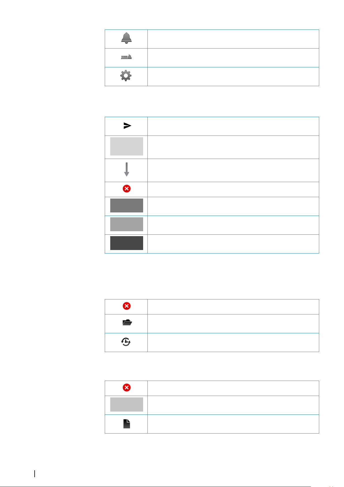
Route icons
Opens the Alerts menu.
Opens the Targets menu.
Opens the Settings dialogs.
Transfers the route to another unit
Indicates a waypoint in the route menu
Indicates a leg in the route menu
Deletes a selected waypoint/event mark
Moves a selected waypoint up in the list of waypoints
Moves a selected waypoint down in the list of waypoints
Opens the waypoint/event mark edit menu
Chart management icons
Chart library
Deletes a selected database
Opens the chart catalog of a selected database
Searches for updates for a selected database
Chart catalog
Deletes a selected dataset
78
Highlights the dataset in the chart, and moves chart center to the
selected dataset
Opens additional information for a selected dataset
Icons| E50xx ECDIS Operator Manual
Page 79

Icons in Manual update menus
Refreshes the list of datasets currently displayed in the chart view
Add Manual update object
Opens the child editing menu
Opens the attribute editing menu
Opens the geometry editing menu
Modify Manual update objects
Opens the child editing menu
Opens the object editing menu
Opens the geometry editing menu
Highlights the object in the chart, and moves chart center to the
selected object
Deletes the selected object
Manual update history
Displays/hides the object in the chart
Opens the object editing menu
Highlights the object in the chart, and moves chart center to the
selected object
Deletes the selected object
Icons| E50xx ECDIS Operator Manual
79
Page 80
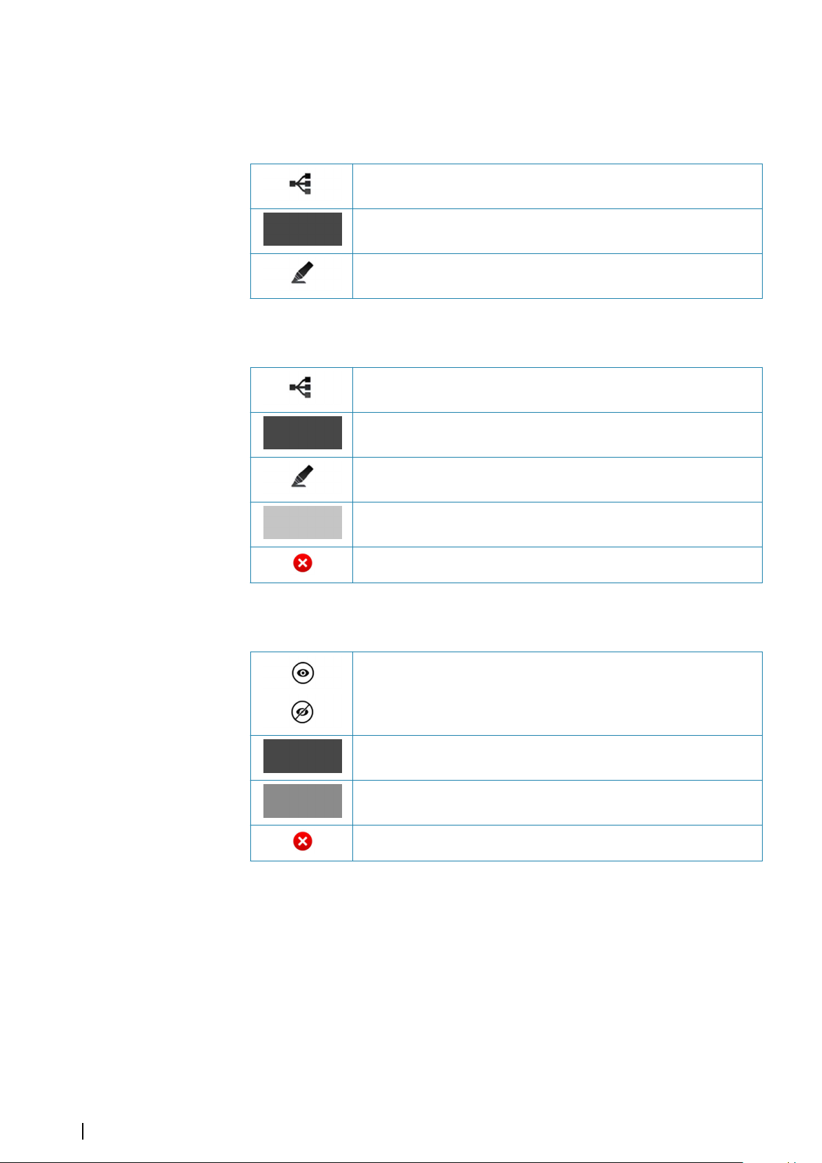
User chart objects menu icons
Add User chart object
Opens the child editing menu
Opens the attribute editing menu
Opens the geometry editing menu
Modify User chart object
Opens the child editing menu
Opens the object editing menu
Opens the geometry editing menu
Highlights the object in the chart, and moves chart center to the
selected object
Deletes the selected object
User chart objects, icons in history menus
Displays/hides the object in the chart
Opens the object editing menu
Highlights the object in the chart, and moves chart center to the
selected object
Deletes the selected object
80
Icons| E50xx ECDIS Operator Manual
Page 81

System settings icons
SA certificates
Refreshes the SA certificates list
Removes the SA certificate
Installs the SA certificate
Grounding check
Increases the value of a setting
Decreases the value of a setting
Object information icons
Highlights the object in the chart, and moves chart center to the
selected object
Displays an image file related to the selected object
Displays a txt file with additional object information in a separate
window
Target symbols
This section lists the target symbols used in this system.
Symbol Description
AIS Base station
AIS SAR aircraft
AIS SAR vessel
AIS SART (AIS Search And Rescue Transmitter)
AIS target - Dangerous, indicated with bold line and with red
color. The symbol flashes until the target alarm is acknowledged by
the operator
AIS target - Lost, indicated with crossed lines centered on the
target symbol. The symbol is located at the last received position
from the target
Icons| E50xx ECDIS Operator Manual
81
Page 82

Symbol Description
+
Off Posn
Racon err
AIS target - Selected, indicated with a square (dotted line) around
the target symbol
AIS target - Sleeping, aligned with received heading information
or with COG information if heading is not available
AIS target, activated - True scaled outlines
AIS target with heading line and SOG/COG (dotted line), and with
indicated turn direction
AIS target with heading line, SOG/COG (dotted line) and past track
Associated target - using AIS data
Physical AIS AtoN, basic shape (AIS aids to navigation)
Physical AIS AtoN - East cardinal mark
Physical AIS AtoN - Emergency wreck mark
Physical AIS AtoN - Isolated danger
Physical AIS AtoN - North cardinal mark
Physical AIS AtoN - Off position
Physical AIS AtoN - Port hand mark
Physical AIS AtoN - Racon failure
82
Physical AIS AtoN - Racon
Physical AIS AtoN - Safe water
Physical AIS AtoN - South cardinal mark
Icons| E50xx ECDIS Operator Manual
Page 83
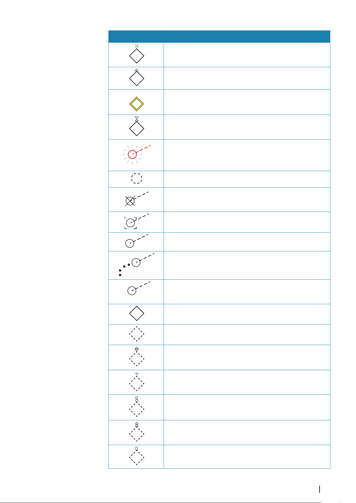
Symbol Description
Unlit
18
R
SS
+
+
+
+
+
+
Physical AIS AtoN - Special mark
Physical AIS AtoN - Starboard hand mark
Physical AIS AtoN - Unlit (failure of lights)
Physical AIS AtoN - West cardinal mark
Radar target - Dangerous, indicated with bold line and with red
color. The symbol flashes until the target alarm is acknowledged by
the operator. It remains red until the system no longer defines it as a
dangerous target
Radar target - in acquisition state, indicated as a broken circle
centered at the position of target acquisition
Radar target - Lost, indicated with crossed lines centered on the
target symbol. The symbol is located at the last received position
from the target
Radar target - Selected, indicated with a square (dotted line)
around the target symbol
Radar target - Tracked, with velocity vector
Radar target with past position and velocity vector
Reference target
Signal station
Virtual AIS AtoN, basic shape
Virtual AIS AtoN - East cardinal mark
Virtual AIS AtoN - Emergency wreck mark
Virtual AIS AtoN - Isolated danger
Virtual AIS AtoN - North cardinal mark
Virtual AIS AtoN - Port hand mark
Icons| E50xx ECDIS Operator Manual
83
Page 84
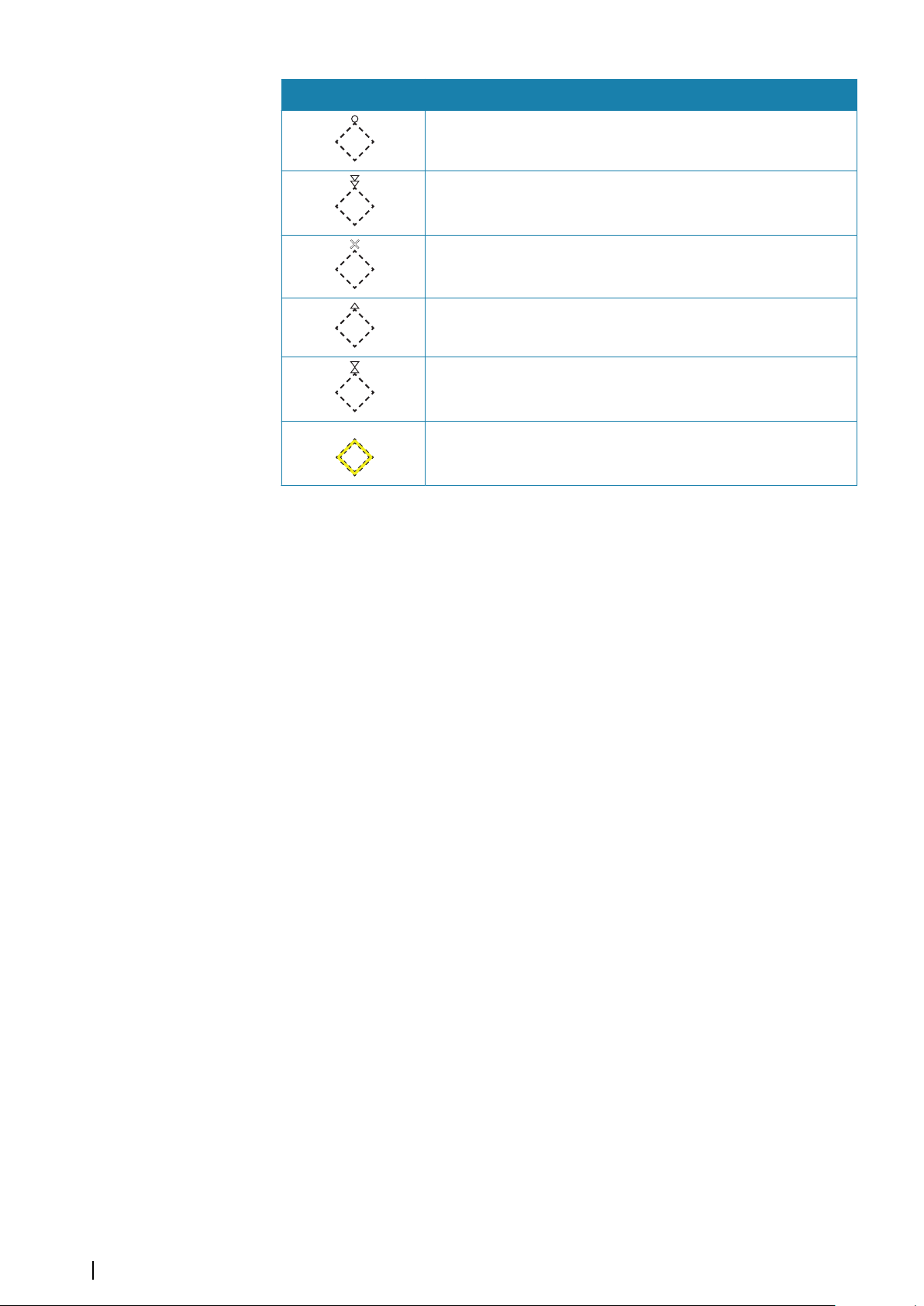
Symbol Description
+
+
+
+
+
Missing
Virtual AIS AtoN - Safe water
Virtual AIS AtoN - South cardinal mark
Virtual AIS AtoN - Special mark
Virtual AIS AtoN - Starboard hand mark
Virtual AIS AtoN - West cardinal mark
Virtual AIS AtoN Missing
84
Icons| E50xx ECDIS Operator Manual
Page 85

Index
A
Abbreviations
Acknowledging alerts 69
Activating
Anchor watch 37
AIS 38
Communicating with other vessels 40
Create messages 41
Filters, enabling 40
Own ship AIS status 41
Setting own vessel status 40
Target filter settings 40
View sent or received AIS messages 41
AIS Filter 11, 76
AIS targets 38
Configuring 39
Display settings 39
Heading line 39
Hide AIS targets 39
Past track 39
Path predictor 39
Range circles 39
Show associated as AIS 39
Symbols 38
Target label 39
True scale outline 39
Velocity vector 39
Alarm panel
E0102 Alarm panel 9
Alarms
Power failure 69
Alert graphics
Filtering visible alert items 32
Alert notifications 68
Alerts list 70
Anchor watch 36
activating 37
Deactivating 37
Setup 36
Area 28
ARPA radar 38
ARPA targets 38
B
Backup
User data 66
Best scale 19, 28
Brightness 18
Brilliance 11, 18, 76
C
Chart center 19
Moving 19
Panning 19
Chart library 24
Chart objects 27
Adding mariner objects 59
Adding user chart objects 59
73
Chart orientation 11, 28, 76
Course-up
Head-up 28
North-up 28
Track-up 28
Chart permit code 20, 22
Chart permits 23
Installing 23
Chart scale 19
Selecting 19
Zooming 19
Chart scale: scrolling 19
Chart settings 25
Portrayal settings 25
Chart subscription 21
Chart symbol size 26
Chart symbols 30
Chart viewing date 27
Charts
Catalogs 56
Chart library 56
Database 9, 55
Display 24
Displaying information about 55
Highlight chart updates 57
Management 55
Manual update history 60
Manual updates 58
Mariner objects 58
Mariner objects history 60
Show update history on chart 57
Update history 57
User chart objects 58
User chart objects update history 60
Color calibration 18
Color mode 26
Course-up 28
Create AIS messages 41
Create new route 11, 76
D
Danger objects 51
Danger symbols 26
Date
Chart view date 27
Datum transformation 35
Deactivating
Anchor watch 37
Dead Reckoning 36
Enable correction 36
Deep contour 26
Depth display settings 26
Color mode 26
Deep contour 26
Safety contour 26
Safety depth 26
Shallow contour 26
Shallow pattern 26
Display brightness 18
28
Index | E50xx ECDIS Operator Manual
85
Page 86

Brilliance 18
Display mode
Base 27
Custom 27
Full 27
Standard 27
Display palettes 19
Display
Verifying color 65
Distance from leg 26
E
E0102 Alarm panel 69
E5000 Processor 8
EBL 33
ECDIS Requirement 8
Economic speed 47
Electronic Bearing Lines 33
Enable correction 36
Enable light character 26
EPFS 14
Estimated position 36
Event marks 50
Adding 50
Exporting routes 52
F
Fault finding 71
Filter settings option
AIS 40
Filter
Alert items on chart 32
Filters
Enabling AIS filters 40
Fixed position 28
Follow own vessel 11, 76
Full light lines 26
G
Geodesic calculation 34
Great circle approximation 34
Grounding check 31
Guard zone 31
Cardioid 31
Defining 31
Sector 31
H
Head-up 28
Heading line
Display AIS targets 39
Hide AIS targets 39
I
Icons 76
Chart management 78
Chart panel 77
General interface 77
11, 27, 76
Main menu 77
Manual updates
Object information 81
Route menus 78
System settings 81
User chart objects 80
IMO 8
Importing routes 52
Indications 69
Installing charts 20
NavStick 20
Other suppliers 23
Instrument bar 14
K
Keep best scale 28
Keyboard 16
L
Layers 11, 14, 38, 76
Leg activation scale 26
Light distance 26
Light indicator 11, 76
Lines Of Position 35
Log book 61
Logitech 9
LOP 35
LTSX50 9
M
M570 Trackball 9
Main menu 11, 12, 76
Main panel 10
Maintenance 65
Connectors 65
Man Over Board 12, 31, 77
Manual observation 35
Manual
About 4
Version 4
Mariner objects 15
Adding 59
Maximum speed 47
Measure 11, 76
Measuring 33
Bearing 33
Distance 33
Messages 68
Acknowledging 69
AIS 41
Alarms 68
Alert notifications 68
Indications 69
Navigational cautions 68
Warnings 68
MOB 12, 31, 77
Displaying 31
Removing 31
Saving 31
79
86
Index | E50xx ECDIS Operator Manual
Page 87

Monitor 9
Move chart center
N
Navigation panel 14, 54
Navigational area 28
Area 28
Fixed position 28
Navigational calculations 34
Datum transformation 35
Geodesic calculation 34
Great circle approximation 34
Navigational cautions 32
Displaying information about 32
Navigational settings 28
Navigations 54
NavStick 9, 20
Copy content 22
Updating 22
NavSync 20
NAVTOR 9
NavTracker 20, 21
North-up 28
O
Object information 15
On-screen keyboard 16
Other vessels 38
Overview map 14
Own ship AIS status 41
Own vessel's display settings 29
Past track 29
Path predictor 29
Radar antenna position 29
Track 29
True scale outline 29
Velocity vectors 29
P
Palette 11, 76
Palettes 19
Panel menu 12
Panning 19
Paper chart symbols 26
Parallel index lines 33
Parallel indexing 32
Past track 29
Display AIS targets 39
Path predictor 29
Display AIS targets 39
Permits
Chart permits 23
PLECDIS 9, 62
Automatic data synchronization 63
Defining main and backup systems 62
Manual data synchronization 64
Portrayal settings 25
Chart symbol size 26
Danger symbols 26
16
Distance from leg 26
Enable light character
Full light lines 26
Leg activation scale 26
Light distance 26
Paper chart symbols 26
Scale min 26
Symbolized boundaries 26
Portrayal style 26
INT1 26
S52 26
Power failure alarm 69
Power off 18
R
Radar 15
Radar antenna position 29
Radar overlay 15
Radar targets 42
Configuring 43
Display settings 42
Symbols 42
Range circles
Display AIS targets 39
Range rings 33
Regulatory statements 3
Restore defaults 11, 77
Restore
To factory settings 66
User settings 66
Routes 46
Adding an event mark 50
Adding and moving waypoints 49
Copying 51
Create new 48
Danger objects 51
Deleting a waypoint 50
Deviation 47
Displaying 48
Economic speed 47
Exporting 52
Importing 52
Maximum speed 47
Menus 46
Modifying 49
Navigating 54
Planning 46
Route details 46
Route edit menu 46
Route list 46
Settings 47
Transfer to another unit 53
Turn radius 47
S
S57 9, 20, 55
S63 9, 20, 55
Safety contour 26
Safety depth 26
26
Index | E50xx ECDIS Operator Manual
87
Page 88

Scale min 26
Scale-dependent objects
SCAMIN 26
Scrolling 19
Send
AIS message 41
Route to another unit 53
Sensors 14
Invalid 14
Missing 14
Valid 14
Settings dialogs 13
Shallow contour 26
Shallow pattern 26
Shortcut buttons 11, 76
Show associated targets as AIS 39
SI80 Signal Interface unit 9
Signal Interface unit 9
Software upgrades 66
SOLAS 8
Start-up 18
Stop route 11, 76
Sub dialog 13
Submenus 12
Symbolized boundaries 26
System start-up 18
26
Calculating 35
View sent or received AIS messages
Voyage
Starting 54
Stopping 54
VRM 33
W
Warnings
Lost targets 45
Warranty 3
Wheelmark 3
Z
Zoom buttons 19
Zooming 19
41
T
Target information 43
Target label
Display AIS targets 39
Targets
Finding 44
Lost 45
Update frequency 45
Terms 73
Track 29
Track-up 28
Trackball 9, 18
Transfer
Route to another unit 53
True scale outline 29
Display AIS targets 39
Turn off
Anchor watch 37
Turning the system off 18
U
User chart objects 58
adding 59
Update history 60
User permit code 20
88
V
Variable Range Marker 33
Velocity vector 29
Display AIS targets 39
Vessel motion 11, 76
Vessel position 35
Index | E50xx ECDIS Operator Manual
Page 89

Page 90

*988-10782-002*
www.navico.com\commercial
 Loading...