

Page 1

Manual
Navico DSC1400
Class D DSC Controller
Page 2

Page 3Page 2
CONTENTS
1. General
1.1 Introduction
1.2 Technical Summary
1.3 MMSI Number
1.4 Keypad
1.5 Softkeys
1.6 Distress Button
1.7 Working Channels
2. Sending a Call
2.1 General
2.2 Routine
2.3 Urgency & Safety
2.4 Group Call
2.5 Distress Alert
3. Receiving a Call
3.1 General
3.2 Routine
3.3 Urgency & Safety
3.4 Group Call
3.5 Distress Alert
4. Additional Functions & Configuration
4.1 Call Log
4.2 Directory
4.3 Backlighting
4.4 Contrast
4.5 Sound
4.6 MMSI
4.7 Group ID
4.8 Date & Time
4.9 Manual Position
4.10 Channels
5. Installation
5.1 Fitting the DSC1400
5.2 Electrical Installation
5.3 Interfacing via NMEA
5.4 Startup
6. Operating Procedures
6.1 Sending a Distress Alert
6.2 Cancelling a Distress Alert
6.3 Acknowledging a Distress Alert & Relaying Alert
6.4 Alerting All Vessels Within Range
6.5 Calling a Coast Radio Station
6.6 Making an Intership Call
7. Appendix
7.1 Warning to Users
7.2 Important Information
7.3 Service & Warranty
The technical data, information and illustrations contained in this publication were to the best of our knowledge correct at the time of going to print. We reserve the
right to change specifications, equipment, installation and maintenance instructions without notice as part of our policy of continuous development and improvement.
No part of this publication may be reproduced, stored in a retrieval system or transmitted in any form, electronic or otherwise without prior permission from
Simrad Navico Ltd.
No liability can be accepted for any inaccuracies or omissions in the publication, although every care has been taken to make it as complete and accurate as possible.
MDL 2/12/98
E02610 Issue 1.2
© 1999 Simrad Navico Ltd
Simrad Navico Ltd
Star Lane, Margate, Kent CT9 4NP, UK
Telephone +44 (0) 1843 290290
Facsimile +44 (0) 1843 290471
E-Mail : sales@simrad-navico.co.uk
Page 3
Page 5Page 4
1 General
1.1 Introduction
The DSC1400 is a Class D Digital Selective Calling (DSC) Controller designed for use with the
Axis RT1400 VHF radio. With a DSC1400 the RT1400 will support the latest GMDSS requirements
for non-SOLAS vessels from the International Maritime Organisation (IMO). It will enable you to
make digitally selected calls, which are quicker and simpler to make than traditional voice calls
using Channel 16. Should a distress situation occur, with the DSC1400 you can quickly raise an
alert, indicating your identity, your position and automatically establish distress communication
on the emergency voice channel.
Thank you for choosing Simrad
If you are pleased with your DSC controller we hope you will be interested in our range of marine
electronic equipment, which is manufactured to the same high standards as Axis. Please contact
your nearest Simrad Agent for a catalogue showing our full range of high tech marine electronic
equipment.
Simrad Navico operate a policy of continual development and reserve the right to alter and
improve the specification of their products without notice.
Axis
®
is a Registered Trade Mark of
Simrad Navico Ltd
DSC1400 Class D Digital Selective Calling Controller
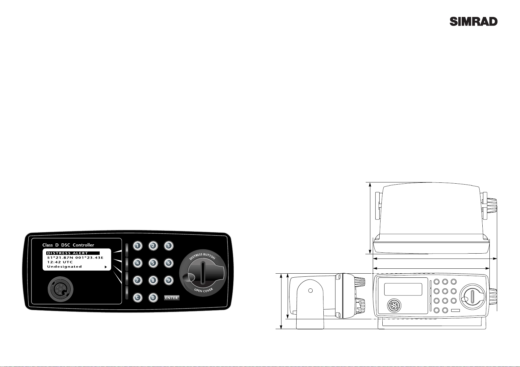
1.2 Technical Summary
Display 122 x 32 pixels
54.8 x 19.1mm (2.19 x 0.76 in) viewing area
Controls ITU Keypad
4 multi function softkeys
Distress button with safety cover
Connections Front 7 way plug for handset / fistmike
Rear cable with 7 way socket for RT1400 connection
Rear cable for NMEA0183 position input
Power 12v DC (Supplied by RT1400)
Weight 0.5 kg
Mounting Desktop, bulkhead or panel mount (uses same mounting accessories as RT1400)
Type Approval Meets EN301-025, Class D DSC Specification
Operating Temp -15 to +55¼C
Humidity 0 to 95% non-condensing
168mm (6.72 in)
180mm (7.20 in)
105mm (4.20 in)
60mm (2.40 in)
90mm (3.60 in)
Fig 1.1 - Dimensions
Page 4
Page 7Page 6
2 Sending a Call
2.1 General
Making a DSC call using the DSC1400 is very
simple. First, choose the call type (Routine,
Safety, Urgency, Group or Distress Alert). If
required, enter the destination and working
channel, then press ENTER.
2.2 Routine
To make a routine call, either enter an MMSI
number with the keypad from the main screen
or press Call and use theTo key to cycle through
the numbers which have been previously
entered into the directory (see section 4.2).
If the call is to a coast station, then the channel
will be displayed on the screen as --, as the
acknowledgement from the station will automatically tune the VHF to the working channel,
which is selected by the coast station (Fig 1.5).
If the call is to another vessel, a working channel can be specified by pressing the channel
softkey to select a channel from the list (see section 4.10). Alternatively, this can be selected
using the channel knob on the RT1400.
Press ENTER to send the call. The DSC1400
will indicate that it is waiting for a reply. When
the reply is received, the RT1400 will automatically set to the specified working channel. A
voice call can then be made in the normal way.
2.3 Urgency & Safety
While the Routine DSC call will only be heard
by the station or vessel with the specific MMSI
number entered, both Urgency and Safety calls
are All Ships calls - they will be heard by any
vessel or station within VHF range.
From the main screen, press Call twice to select
Safety Call (Fig 1.6) or three times to select
Urgency Call. While you may use the RT1400
channel select knob to select a different working channel when making a Safety Call (default
is 16), Urgency Calls always use channel 16.
1.3 MMSI Number
For the DSC1400 to function an MMSI
(Maritime Mobile Service Identifier) number
will need to be entered. This can be obtained
from the local radiocommunications authority.
1.4 Keypad
The telephone style ITU keypad is used for
entering numeric data. When required, the
keys will automatically switch to character
mode allowing letters, numbers and punctuation characters to be entered. Repeatedly
pressing a key will cycle through the characters
available on that key (Fig 1.2).
The Cancel key will stop a task and return to the
main screen. The ENTER key is used to confirm
actions, such as sending a call.
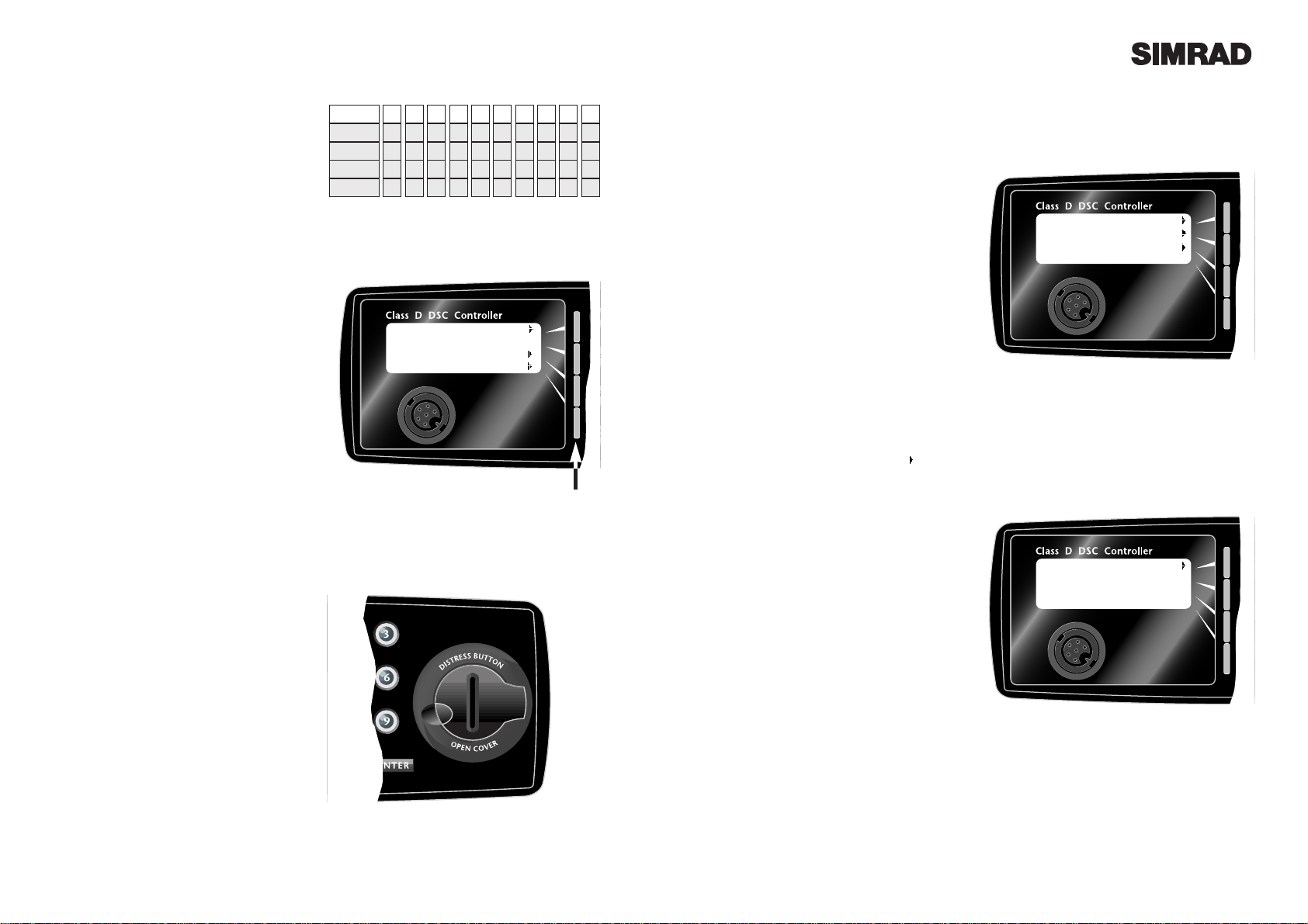
1.5 Softkeys
The functions of the four softkeys - one for each
line of the display (Fig 1.3) - will change to suit
the menu that is currently displayed. A label
indicating the function of the softkey will be
displayed on the right side of the corresponding display line.
1.6 Distress Button
The distress button is located under a protective cover that must be lifted before the button
can be pressed (Fig 1.4).
THIS BUTTON
MUST ONLY BE USED IN A DISTRESS
SITUATION. Refer to section 2.5 for more
details.
1.7 Working Channels
While all DSC transmissions from the DSC1400
are made digitally on channel 70, once the call
has been put through, communication with the
other vessel or station will be via a normal
voice channel, which is specified when the call
is made. This is referred to in this manual as a
working channel
0 1 2 3 4 5 6 7 8 9
sp
-
A D G
J
M P T
W
(
,
B E H K N Q U X
)
. C F I L O R V Y
% / ? ! : " ' S & Z
1 Press
2 Presses
3 Presses
4 Presses
5 Presses
Fig 1.2 - Keypad character map
1
4
7
C
Fig 1.3 - Softkeys
Softkeys
Fig 1.4 - Distress Button
1
4
7
C
Routine call
To SOLENT C’GUARD
On --
52º02’N Call
001º35’E
08:54 UTC Log
Ch 06 Menu
Fig 1.5 - Sending Routine Call
1
4
7
C
Safety Call call
To ALL SHIPS
On 16
Fig 1.6 - Sending Safety Call
Page 5

Page 9Page 8
Press the ENTER key to make the call. The
DSC1400 will require confirmation of the call.
Press Ye s to send the call, or No to cancel.
When the DSC call is sent, the RT1400 will be
set to the working channel. Allow a few seconds for the stations receiving the call to switch
to the working channel, then make a normal
voice call on the specified working channel.
2.4 Group Call
If a group ID has been set up for the DSC1400
(see section 4.7), a call can be made to other
members of the group.
Press the Call key four times to select the Group
Call screen. Select a working channel from the
list (see section 4.10) by pressing the channel
softkey or use the RT1400 channel select knob
(Fig 1.7).
Press ENTER to send the call, allow a few seconds for the other members of the group to
reach their radios (all VHF radios in the group
should automatically switch to the specified
working channel upon acknowledgement),
then make a normal voice call using the working channel.
2.5 Distress Alert
NOTE - THIS CALL SHOULD ONLY BE
MADE IF THE VESSEL IS IN A DISTRESS
SITUATION. It is an offense to send a Distress
Alert call if the vessel or crew are not in danger.
Refer to section 5.1 for more details.
Lift the protective cover and press the DIS-
TRESS button. The Distress Alert Screen will
be displayed. If time permits, press the designation softkey to select the nature of the distress. There are 10 categories recognised as
Distress Alert situations, which are Abandoning, Adrift, Collision, Fire, Flooding,
Grounding, Listing, Man Overboard, Piracy
and Sinking. There is also a default
Undesignated category, which is used if no category is selected here.
Press and hold the DISTRESS key a second
time, holding it down for five seconds (Fig 1.8).
An alarm will sound and a countdown to the
transmission will be displayed.
The Distress Alert transmission contains the
following data -
* The vessel's MMSI
* The vesselÕs position (either from the
NMEA0183 input, or manually entered)
* The time (from NMEA or manual)
* The nature of the distress
After the Distress Alert has been sent, the
RT1400 will automatically tune to channel 16
and the DSC1400 will repeat the Alert approximately every four minutes until either an
acknowledgement is received, or C is pressed
(it is not recommended that the Distress Alert
is cancelled manually by pressing C unless
you are requested to do so by the rescue
authorities).
While the Distress Alert remains active, an
intermittent alarm will continue to sound.
When an acknowledgement is received from
the Rescue Co-ordination Centre, this will cancel the Distress Alert transmission from the
DSC1400 and automatically switch the RT1400
to the required working channel. The subsequent rescue co-ordination will be performed
using the voice working channel.
1
4
7
C
Group call
To 100000000
On 06
D
I
S
T
R
E
S
S
B
U
T
T
O
N
O
P
E
N
C
O
V
E
R
1
4
7
C
DISTRESS ALERT
52º02’N 001º35’E
08:54 UTC
Fire
Fig 1.8 - Sending distress alert
D
I
S
T
R
E
S
S
B
U
T
T
O
N
O
P
E
N
C
O
V
E
R
HOLD FOR 5 SECS
1
4
7
C
2
5
8
0
3
6
9
ENTER
D
I
S
T
R
E
S
S
B
U
T
T
O
O
P
E
N
C
O
V
E
R
ENTER
Fig 1.7 - Sending Group Call
Page 6

Page 11Page 10
3 Receiving A Call
3.1 General
When a DSC call is received, the DSC1400 will
switch to the call log screen to display the
details of the call and ring or sound the alarm depending on the nature of the call. The procedures that follow describe how to handle the
types of calls that can be received.
3.2 Routine Calls
When a Routine call is received, the screen will
show the details of the call, who it is from and
the working channel (Fig 3.1). To stop the ringing, press the softkey. An acknowledgement will be sent to the caller and the radio will
be automatically switched to the working channel for normal voice communication.
3.3 Urgency and Safety
The procedures for Urgency and Safety calls are
very similar. An Urgency call will sound the
distress alarm and switch the RT1400 to channel
16. A Safety call will sound a normal ring and
switch the RT1400 to the specified working
channel (Fig 3.2). Press the softkey to stop
the ringing, then listen for the voice message.
3.4 Group Calls
When a Group call is received, the DSC1400
will display the details of the call, indicating
who it is from and the working channel. Press
the softkey to stop the ringing and the
RT1400 will switch to the working channel
automatically.
3.5 Distress Alert
If a Distress Alert or a Distress Relay is received
from another vessel, an alarm will sound and
the RT1400 will switch to channel 16. The display will show the details of the Distress Alert,
the MMSI of the vessel, itÕs position and time.
Mute the alarm by pressing the softkey and
maintain a listening watch on channel 16 for the
distress messages. Press C to clear the display.
4 Additional Functions & Configuration
4.1 Call Log
The call log can be used to look back through
the previous 20 calls that have been received,
the most recent call first. To access the log
press the Log softkey in the main screen.
The and softkeys are used to move back
and forward through the log (Fig 4.1). Use the
and softkeys to display longer messages.
The bottom left of the display shows the time
the call was received in the form of dd/hh:mm.
4.2 Directory
The Directory screen is used to add, edit and
delete entries from a list of up to 20 stored
MMSI numbers, which can be recalled in the
Routine Call screen (see section 2.2).
To access the directory function, press Menu in
the main screen, then Directory.
To create a new entry, press Add. Use the keypad to enter a name of up to 14 characters,
numbers or symbols (see section 1.3 for further
information on the keypad character set). Use
the and keys to move backwards and forwards along the line (Fig 4.2).
When the name has been entered, press MMSI
to enter the MMSI number (9 numbers). Press
ENTER to store the directory entry.
To edit an existing entry, press Next to select
the appropriate name and then Edit. Use the
and keys to move along the name field and
use the keypad to edit the details. Press MMSI
to change the MMSI code. Press ENTER to
store the modified entry.
To delete an entry, press Next to select the
appropriate name and then Delete. Confirm
that the entry is to be deleted by pressing Yes ,
or press No to leave the entry in the directory.
Press C to return to the main screen.
1
4
7
C
Routine call
From 233004567
On 06
1/04:31
Fig 4.1 - Call log display
1
4
7
C
Silver Spirit Name
MMSI
Fig 4.2 - Entering name into directory
1
4
7
C
Routine call
From 233004567
On 06
1/04:31
Fig 3.1 - Routine Call received
1
4
7
C
All Ships safety
From 233004567
On 16
1/04:31
Fig 3.2 - Safety call received
Page 7

Page 13Page 12
4.3 Backlighting
The backlighting of the DSC1400 display and
keypad is linked to the backlighting of the
RT1400 display and keypad - if the lighting is
adjusted on the RT1400, the same changes
affect the DSC1400 and vice versa.
To change the backlighting of both units from
the DSC1400, press Menu, then press Backlight
the required number of times to select the
desired lighting level (Fig 4.3). Note that the
Distress key is always faintly lit even when the
backlighting is switched off.
4.4 Contrast
To adjust the contrast of the DSC1400 display,
press Menu, then Contrast. Use the - and +
softkeys to decrease or increase the contrast
level. The display shows a bar graph indicating the selected contrast level.
Press C to exit to the main screen.
4.5 Sound
The sound option allows the alarm and ringing
tones to be tested and changed. Press Menu,
then , then Sound.
To test the Distress Alert alarm, press Test
Distress. Press C to cancel the test.
To test the ringing tone, press Test Ring. Press
C to cancel.
To select one of four different ringing tones,
press Ring Type until the preferred ringing
sequence (1-4) is shown. Press Test Ring to
hear each sequence.
Note that the alarm and ringing tones are at a
set volume level and cannot be muted.
4.6 MMSI
To show the MMSI number programmed into
the DSC1400 and also the software version
number of the unit (necessary if a fault develops with the unit), press Menu, then , then
MMSI (Fig 4.5).
Press C to exit to the main screen.
4.7 Group ID
To enter a Group ID (if for example, the vessel
is part of a flotilla or fishing fleet etc) press
Menu, then , then Group (Fig 4.6).
Use the keypad to enter the Group ID and
press ENTER to select.
Press C to exit to the main screen.
4.8 Date & Time
Normally, the date and time is supplied by the
NMEA0183 navigational input (from a GPS
etc). If a navigator is not connected, or the signal has been lost, the missing data can be manually entered here. Press Menu, then twice,
then Date and Time.
Enter the data in the following format (Fig 4.7) -
dd/mm/yyyy hh:mm
Note that the time should be UTC (GMT) and
entered in 24 hour clock format. Press ENTER
to accept the setting and C to return to the main
screen.
4.9 Manual Position
As with the date and time, if the position of the
vessel cannot be obtained from a navigator via
the NMEA0183 input, this data can be entered
manually. Press Menu, then twice, then
Manual Position.
Use the and keys to move along the position and time fields, using the keypad to enter
the required data (Fig 4.8). Press ENTER to
accept the position entered.
If no data is being received from the NMEA
input, a ! symbol will flash after the time on the
main screen display and the DSC1400 will
prompt for a manual input every four hours.
After 23 hours, if the DSC1400 has not received
any position data, either manually or from the
NMEA input then it will show ÒNo position
informationÓ if a Distress Alert is transmitted.
1
4
7
C
Directory
Backlight
Contrast
Fig 4.3 - Adjusting backlighting level
1
4
7
C
Test Distress
Test Ring
Ring Type (1)
Fig 4.4 - Testing distress ring tone
1
4
7
C
MMSI
002326789
DSC1400 v1.1
Fig 4.5 - Displaying MMSI & software version
1
4
7
C
Group ID
000000000
Fig 4.6 - Entering Group ID
1
4
7
C
dd/mm/yyyy hh:mm
01/03/1999 09: 5 5
Fig 4.7 - Manually entering date & time
1
4
7
C
52º02’N 001º35’E
09:55 UTC
Fig 4.8- Manually entering position
Page 8

Page 15Page 14
4.10 Channels
The DSC1400 includes a list of 9 working channels which can be scrolled through when using
the Routine or Group Calling options (see sections 2.2 and 2.4 respectively). The first four
channels are preset as 06, 08, 72 and 77. These
cannot be amended. The remaining five channels are programmable.
Press Menu, then twice, then Channels (Fig
4.9). Use the and keys to move along the
five programmable channels, the and
keys to scroll through the available channels
programmed into the RT1400. To turn the programmable channel off, set it to -- (below 01).
Always consult your local authority requirements when choosing suitable working channels. Be aware of which channels are Duplex
and will not allow ship to ship communication.
Press ENTER to accept settings and return to
the main screen.
5 Installation
5.1 Fitting the DSC1400
Choose a suitable location that is free from
moisture, excessive heat and vibration, and
which is sufficiently close to the RT1400 radio
for the interconnecting cable to reach.
The DSC1400 has been designed to use the
same mounting accessories as the RT1400 and
so can be desktop, overhead or flush mounted.
The MB1000 standard bracket for desktop and
overhead mounting is supplied with the unit
(Fig 5.1), and the flush mounting bracket
FMB1000 is available as a separate accessory.
Allow at least 15mm (0.6in) clearance behind
the DSC1400 for the cables when choosing a
location. Note that, unlike the RT1400, the
DSC1400 is not waterproof and therefore
should always be fitted in an interior position.
5.2 Electrical Installation
To connect the DSC1400 to the RT1400, simply
unplug the Fistmike/Handset from the front of
the RT1400 and plug in the cable from the back
of the DSC1400, which supplies all data and
power to the DSC1400 from the RT1400. Plug
the Fistmike/Handset into the socket on the
front of the DSC1400 (Fig 5.2).
5.3 Interfacing via NMEA
The DSC1400 incorporates an internal
NMEA0183 processor which is used to provide
position, date and time data from an external
navigator - ideally a GPS.
The DSC1400 can process NMEA0183 version
2.0 sentences RMC, GGA and GLL, either of
which will provide the necessary data.
NMEA0183 version 1.5 is also compatible, if
ZDA is provided in addition to GLL.
Brown Ð NMEA Data OUT (+)
Blue Ð NMEA Common (-)
1
4
7
C
Fig 4.9 - Setting working channels
1 2 3 4 5
10 13 09 73 69
Fig 5.1 - Mounting options
F
16
1/25
D/W
SCN
Sq
Vol
M+
MS
AXIS RT 1400
1
4
7
C
2
5
8
0
3
6
9
DISTRESS ALERT
51º21.87N 001º23.43E
12:42 UTC
Undesignated
ENTER
D
I
S
T
R
E
S
S
B
U
T
T
O
N
O
P
E
N
C
O
V
E
R
Class D DSC Controller
Fig 5.2 - Connecting DSC1400 to RT1400 + NMEA
Brown
Data In
Blue
Common
NMEA0183
Page 9

6 Operating Procedures
The following operating procedure summary has been proposed by the UK Maritime and
Coastguard Agency. It is not exhaustive and should not be regarded as a replacement for information provided by the proper two day VHF/DSC training course required for all VHF license holders.
6.1 Sending a Distress Alert
1. Send a Distress Alert using DSC/
2. Wait approx 15 seconds for a DSC acknowledgement from the Coastguard or a ship station.
3. On receipt of a DSC acknowledgement or after about 15 seconds, transmit the Distress
call on channel 16 -
ÒMayday, Mayday, MaydayÓ
ÒThis is (name of vessel repeated three times)
ÒMaydayÓ
MMSI number and name of vessel or callsign, spoken once
Position
Nature of distress
If the vessel is not in Ògrave and imminent dangerÓ, an All Ships Urgency call followed by a spoken ÒPan PanÓ call or a routine call to the nearest coastguard station may be more appropriate. It
is a prosecutable offense to initiate a Distress Alert call for any other reason than that the vessel
and/or crew is in imminent danger.
6.2 Cancelling a Distress Alert
If a DSC Distress Alert is sent accidentally, cancel it immediately on the DSC1400 by pressing the
C button to prevent repeats, then make the following announcement on channel 16 -
ÒThis is (name of vessel, callsign, MMSI)Ó
ÒCancel DSC Alert sent (date & time UTC)
Do not simply cancel the DSC alert without verbally cancelling it as well, otherwise the rescue
authorities will not be aware that this is a false alarm.
6.3 Acknowledging a Distress Alert & Relaying Alert.
When a DSC Distress Alert is received, an audible alarm will sound. Immediately cease any transmission that may interfere with distress traffic and continue a watch on channel 16.
If there is no DSC acknowledgement from a coast station or ship, after a short interval acknowledge by voice on channel 16 -
ÒMayday
(MMSI of vessel in distress repeated three times)Ó
ÒThis is (name of own vessel, repeated three times)Ó
ÒReceived MaydayÓ
(State the assistance you can give).
A similar response should be given to a Distress Relay, using the words ÒMayday RelayÓ instead
of ÒMaydayÓ in the message above.
Page 17Page 16
5.4 Startup
The first time that the DSC1400 is switched on,
it will be necessary to enter the vesselÕs MMSI
number (Fig 5.3). Use the keypad to enter the
9-digit MMSI. If a mistake is made, use the the
key to move back and edit the error. When
the number is entered, the DSC1400 will ask for
verification. It is important that the MMSI
entered is checked carefully, as it can only be
entered once.
To change the MMSI number after it has been
programmed the unit must be returned to an
authorised Simrad Dealer to erase the existing
number.
Once the MMSI is entered and confirmed, the
main screen should show the current position
of the vessel, the time the last position fix was
taken and the channel selected on the RT1400.
If the position is not shown, check the connections and settings of the navigational receiver
used. If there is no signal being received, a !
will flash next to the time. If the ! is not flashing, this indicates that the DSC1400 is using a
manually entered position/time.
1
4
7
C
Fig 5.3 - Entering MMSI number
Set MMSI
000000000
Page 10

Page 19Page 18
6.4 Alerting All Vessels Within Range
If the vessel is outside of coast radio range and needs to issue a safety warning to all vessels within radio range, transmit an All Ships Safety call by DSC. After about 15 seconds transmit on channel 16 the safety call and message as follows -
ÒSecuritŽ, SecuritŽ, SecuritŽÓ
ÒAll stations (or called station)Ó repeated three times
ÒThis is (MMSI and name or callsign of own vessel)Ó
Repeat text of safety message.
6.5 Calling a Coast Radio Station
Enter the MMSI of the station into the DSC1400, either manually or from the directory. When the
call is acknowledged, the working channel for voice communication will be indicated and the
RT1400 will automatically switch to that channel. Make a voice call as normal.
6.6 Making an intership call
Enter the vesselÕs MMSI into the DSC1400, either manually or from the directory. Before sending
the call, enter the inter-ship channel to be used for subsequent communication. When the alarm
sounds on the called vessel, its operator should acknowledge by DSC, then respond by voice on
the selected channel.
If the MMSI number of the vessel is not known, call as now on channel 16. If no response is
received, call on channel 13. This is the GMDSS bridge to bridge communication channel.
7 Appendix
7.1 Warning To Users
Use of marine radio distress procedures is governed by international law and improper use may
incur legal penalties. A Distress Alert should only be activated if your vessel is in Ògrave and
imminent dangerÓ or if a person is lost overboard. Unauthorised users, such as children, should
be instructed not to tamper with this equipment.
If a Distress Alert is activated accidentally, it is vitally important that it be cancelled (see procedure in section 6.2) to avoid others commencing a search for your vessel.
7.2 Important Information
At the time of issue of your vesselÕs radio license, an MMSI (Maritime Mobile Service Identifier)
must be requested. This is a nine digit number which must be permanently entered into the
DSC1400, otherwise it will not function.
If either the boat or the DSC1400 are subsequently sold, the DSC1400 must be returned to an
authorised Simrad Dealer for the existing MMSI number to be erased so that the new ownerÕs
number can be entered.
For European leisure vessels fitted with VHF DSC equipment, a CEPT Short Range Certificate is
required by the operator. Additional requirements, such as GOC or ROC may apply to operators
on commercial vessels. Please enquire with your local licensing authority for full details.
7.3 Service & Warranty
The DSC1400 may be cleaned when necessary by wiping with a damp cloth. The equipment
should be regularly checked by making routine calls to other stations. On an annual basis, test
the Distress Alert button by pressing it ONCE. This will display the Distress Alert screen and
ensure that the button is functioning. Press C to return to the main screen - DO NOT HOLD
DOWN THE DISTRESS BUTTON.
Your DSC1400 should seldom need servicing, but if it is necessary to have the unit repaired, the
warranty card supplied with the unit should have been filled in and sent to Simrad when the unit
was purchased. Please refer to the warranty information for more details.
The unit is guaranteed for 12 months from date of retail sale. If it is necessary to have the unit
repaired, return it carriage prepaid to the agent in the country of purchase with a copy of the
receipted invoice showing the date of purchase. Where possible, return all the components unless
you are certain that you have located the source of the fault. If the original box is not available,
ensure that it is well cushioned in packing; the rigours of freight handling can be very different
from the loads encountered in the marine environment for which the unit is designed.
Page 11

Manufacturer:
Simrad Navico
Star Lane, Margate
Kent CT9 4NP
United Kingdom
Telephone: +44 (0) 1843 290290
Telefax: +44 (0) 1843 290471
E-Mail: simrad-navico.co.uk
WORLDWIDE MANUFACTURER OF M ARINE ELECTRONICS
 Loading...