

Page 1

www.simrad-yachting.com A brand by Navico - Leader in Marine Electronics
Manual
Simrad DD15
Direct Drive
English
www.busse-yachtshop.de | info@busse-yachtshop.de
Page 2

MANUAL
SIMRAD DD15
Direct Drive
20222303A English
www.busse-yachtshop.de | info@busse-yachtshop.de
Page 3

Simrad DD15 Direct Drive
2 20222303 / A
About this document
Rev Date Written by Checked by Approved by
06.04.06 NG IK ThH A
First edition
© 2006 Simrad AS. All rights reserved.
No part of this work covered by the copyright hereon may be reproduced or
otherwise copied without prior permission from Simrad AS.
The information contained in this document is subject to change without prior
notice. Simrad AS shall not be liable for errors contained herein, or for incidental
or consequential damages in connection with the furnishing, performance, or use
of this document.
www.busse-yachtshop.de | info@busse-yachtshop.de
Page 4

Introduction
20222303 / A 3
Contents
1 SYSTEM DESCRIPTION...............................................5
1.1 General .................................................................................................. 5
1.2 How to use this manual......................................................................... 6
1.3 Performance .......................................................................................... 7
1.4 Compatibility in 12 Volts...................................................................... 8
2 CONSTRUCTION .........................................................9
2.1 Electric Motor ....................................................................................... 9
2.2 Planetary gearbox.................................................................................. 9
2.3 Electro magnetic clutch....................................................................... 10
3 INSTALLATION.........................................................11
3.1 Mechanical mounting.......................................................................... 11
Reducing noise and vibrations ................................................... 12
Feedback unit mounting............................................................. 13
Direct drive in combination with rack and pinion system ......... 15
Direct drive in front of pedestal .................................................17
3.2 Electrical connections ......................................................................... 18
3.3 Test the system....................................................................................19
4 MAINTENANCE.........................................................20
5 TECHNICAL SPECIFICATIONS ..................................21
Draglinks .................................................................................... 22
Spare Parts..................................................................................22
www.busse-yachtshop.de | info@busse-yachtshop.de
Page 5

Simrad DD15 Direct Drive
4 20222303 / A
This page is intentionally left blank
www.busse-yachtshop.de | info@busse-yachtshop.de
Page 6
System description
20222303 / A 5
1 SYSTEM DESCRIPTION
1.1 General
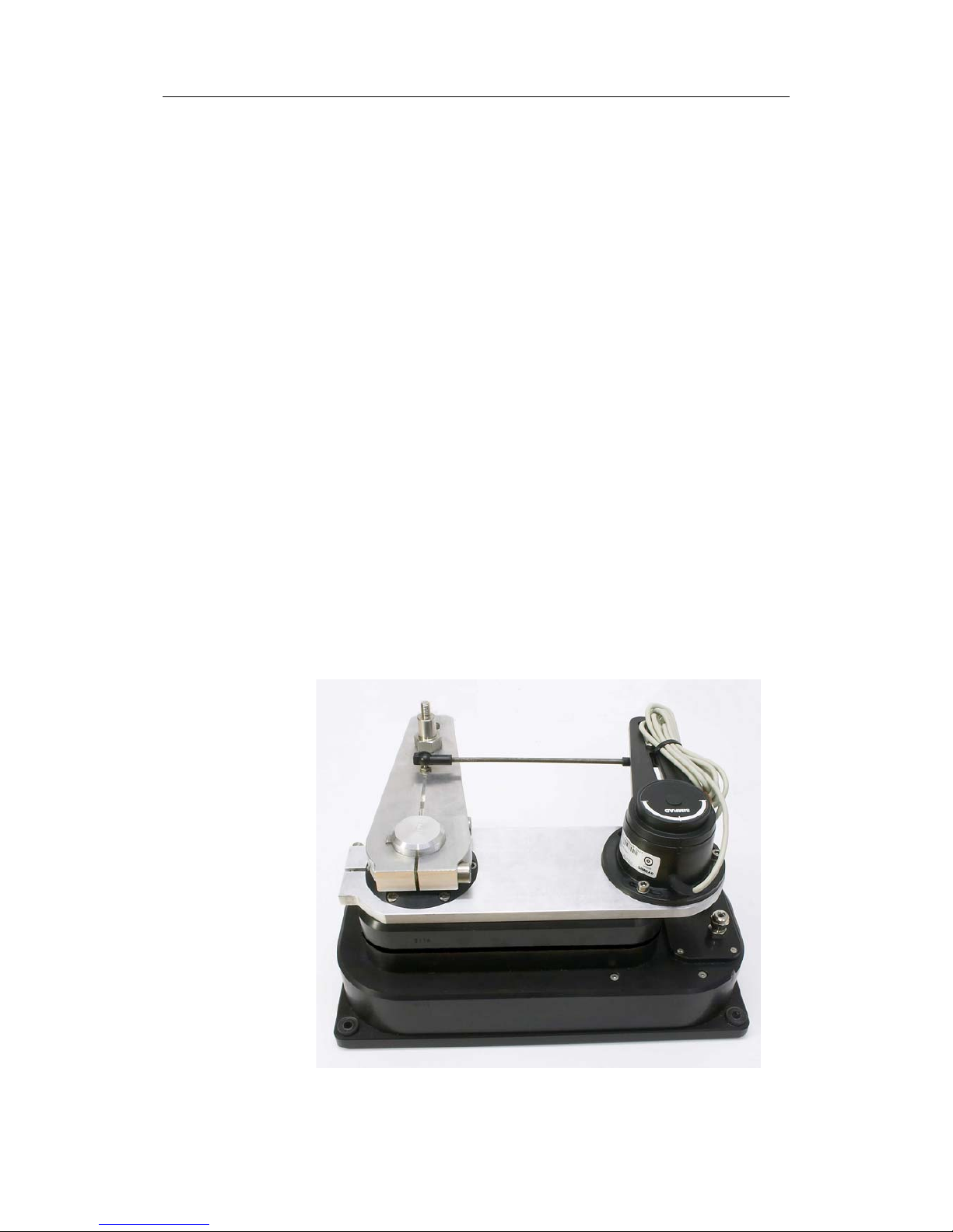
The DD15 Direct Drive is a very strong and compact autopilot
drive and more efficient than hydraulic and most electromechanical autopilot drive units. It is powerful (the max. output
torque of 150 Kgm is equivalent to 150 Kg force on the end of a
1 meter steering tiller) and is build for 24 hours per day
continuous operation with a total weight of only 12 Kgs. The
combination of the flat wound (pancake) electric motor with the
efficient planetary and spur gearbox results in an extremely
efficient drive unit to keep the battery charging time to the
minimum. The drive can be used on boats from 30 to 45 feet
l.o.a. (or up to 150 Kgm rudder torque) equipped with a
mechanical steering system that can be back driven. Due to the
electro mechanical clutch, the direct drive can be back driven
with the force of a finger tip leaving the mechanical steering as
sensitive as without drive unit.
The DD15 includes the Simrad RF300 Rudder Feedback unit
with transmission link and 10 m (30 feet) of cable. It transforms
the angular travel of the rudder to a digital signal read by the
autopilot steering computer.
Figure 1-1 Simrad DD15 Direct Drive (with RF300)
www.busse-yachtshop.de | info@busse-yachtshop.de
Page 7
Simrad DD15 Direct Drive
6 20222303 / A
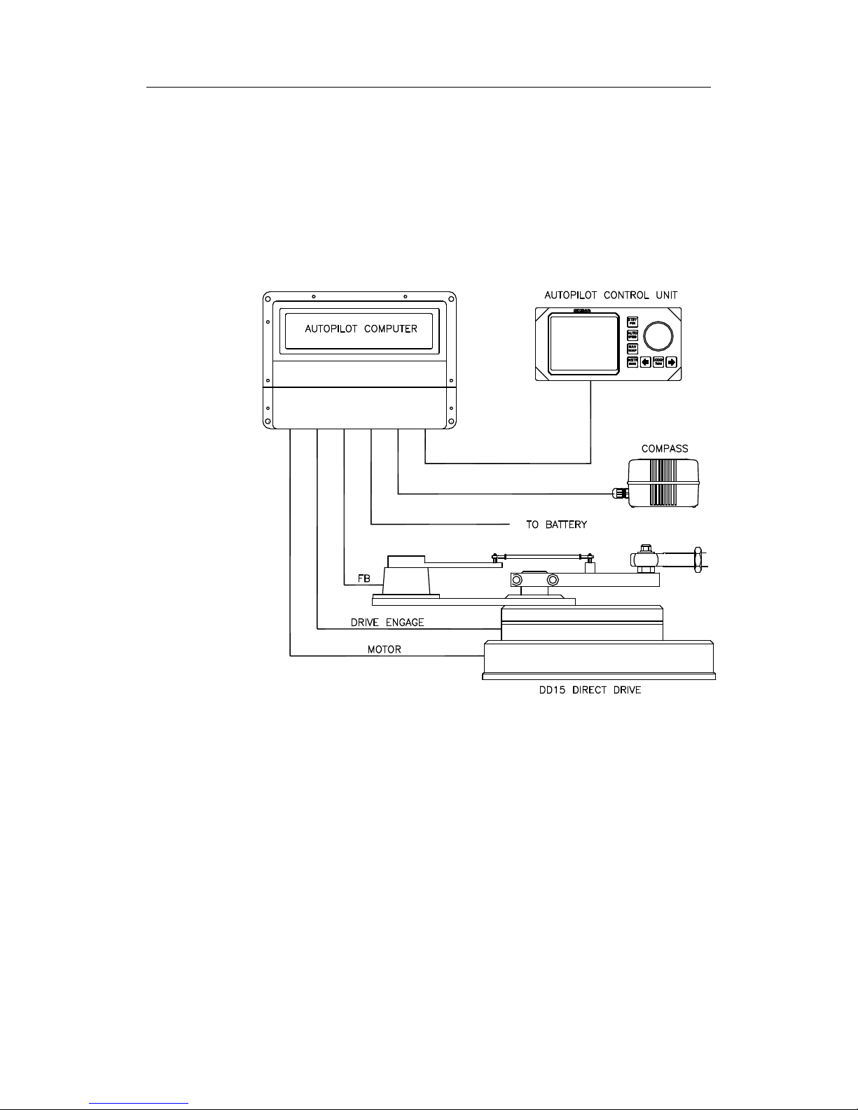
1.2 How to use this manual
This manual is intended as a reference guide for correctly
installing the Simrad DD15 Direct Drive.
Please take time to read the manual to get a thorough
understanding of the use of the drive and the connection to an
autopilot system.
Figure 1-2 Basic autopilot system
This illustration shows the minimum number of components for
a working autopilot configuration.
www.busse-yachtshop.de | info@busse-yachtshop.de
Page 8
Construction
20222303 / A 7
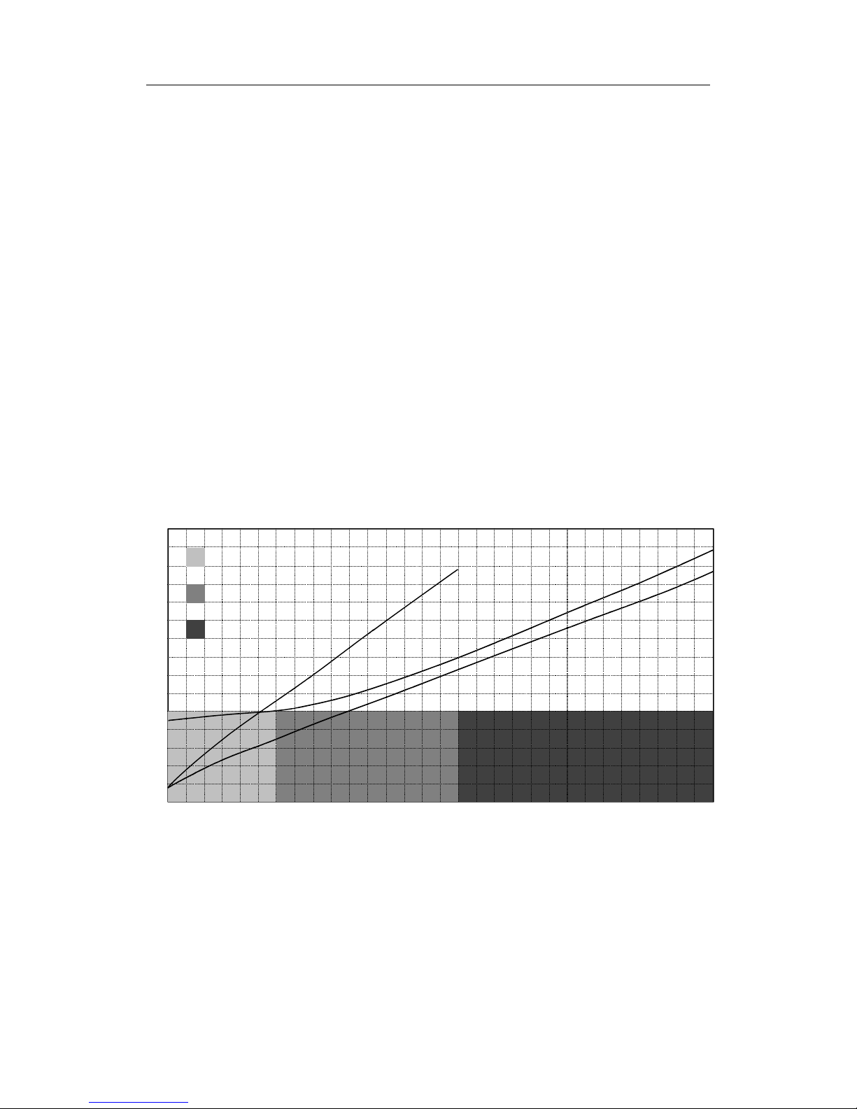
1.3 Performance
The performance table shows the relation between the consumed
power and the output power. The “rudder torque midships” line
shows the output torque against the needed amperage at
midships rudder and the “rudder torque full rudder” line shows
the output torque against the needed amperage at full rudder. The
“hard over time” line shows the hard over time (time to travel
72° of rudder travel) of the drive relative to the output torque.
The table also presents the strength of the drive unit related to
man power. The unit is much stronger than a human being and
can last much longer. One should note however that when the
unit is operated in the dark grey zone, the trim of the boat is not
at its best and the sails should be adjusted to achieve lower
rudder torques. The below table shows that the Simrad direct
drive will steer the yacht even in the worst possible conditions.
As the drive will mostly operate in the light grey zone but not
continuously, the average power consumption on 12 volts is 2
amps.
h
a
r
d
o
v
e
r
t
i
m
e
rud
d
e
r
t
o
r
q
u
e
f
u
l
l
r
ud
de
r
rudder torque midships
0
1
2
150145
140135
3
4
5
6
7
8
9
10
11
12
13
[
A
mp
]
high steering forces,
not manageable by hand power
medium to high steering forces,
manageable for a helmsman for a few minutes
light to medium steering forces,
manageable for a helmsman for a few hours
Drive output torque
[
K
gm
]
0 5 10 15 20 25 30 35 40 45 50 55 60 65 70 75 80 85 90 95 100 105 110 115 120 125 130
2
4
6
8
10
12
14
16
18
20
22
24
[
H
O
-
t
i
m
e
]
Figure 1-3 DD15 Direct Drive performance table
www.busse-yachtshop.de | info@busse-yachtshop.de
Page 9

Simrad DD15 Direct Drive
8 20222303 / A
1.4 Compatibility in 12 Volts
The following table shows the maximum rudder torques at
amidships and full rudder that can be achieved with the Simrad
direct drive in combination with the autopilot computer. The
hard over time (HO-time) states the time it takes the drive to
travel the full 72 degrees of rudder travel when the speed control
of the autopilot is set to maximum speed.
Autopilot computer
12 Volt version.
Max. Output
(Amp.)
Rudder torque
amidships
(Kgm)
Rudder torque
full rudder
(Kgm)
Simrad AC10 (J3000X) 12 73 140
Simrad AC20 (J300X) 20 80 150
Note Even if the AC10 Autopilot Computer is capable of driving the
unit almost to its full power, the AC20 version will have the
necessary extra power when the unit is operating to its extremes.
www.busse-yachtshop.de | info@busse-yachtshop.de
Page 10

Construction
20222303 / A 9
2 CONSTRUCTION
This assembly drawing shows a cross section of the direct drive.
The drive can be separated in 5 main parts: The electric motor,
the two step spur gearbox, the planetary gearbox, the electromagnetic clutch and the final spur reduction gearbox. The
Simrad direct drive has multiple advantages over existing
integrated drive units. These advantages will be explained per
section of the drive:
2.1 Electric Motor
The flat wound electric motor (pancake motor) used in the
Simrad direct drive is carefully selected for this application.
Pancake motors have multiple advantages over normal electric
DC motors:
• A large flat wound rotor to achieve a high starting toque and
an immediate response to the autopilot speed control signal.
• A motor efficiency of 72,5% to achieve a minimal power
consumption and maximal mechanical power output
(compared to max. 50% efficiency of a normal DC motor).
• Compact main dimensions compared to achievable output.
• Aluminum motor housing in stead of sheet steel plate to
avoid corrosion.
2.2 Planetary gearbox
To achieve a correct rudder travel speed (hard over time) the
electric motor has to be reduced in speed with a factor 750:1.
Some autopilot drive producers use a worm reduction box, but
the efficiency is extremely low as the gears rub each other. The
Simrad direct drive uses a combination of a planetary gearbox
and spur gear sets (one small gear and one big gear). The
planetary gearbox has following advantages:
www.busse-yachtshop.de | info@busse-yachtshop.de
Page 11

Simrad DD15 Direct Drive
10 20222303 / A
• The highest possible efficiency compared to any other
gearbox.
• All forces are equally spread over 3 gear teeth in stead of
one allowing a much compacter and stronger solution.
• The forces and torques from the motor to the output shaft
remain in the center line of the drive unit, resulting in a
higher efficiency and extremely reduces the loads on the
housing and other internal parts.
2.3 Electro magnetic clutch
On the moment the mechanical steering system on the yacht is
manually operated, the autopilot drive has to be disconnected
from the steering system. This is achieved with the unique and
patented electro-magnetic engagement clutch, controlled
automatically by the autopilot computer. The solution is based
on two electrically operated spring loaded clutch pins that
engage and disengage the outer gear ring of the planetary gear
step. This solution has multiple advantages over the existing
friction plate clutches:
• Less friction to back drive the unit.
• Lower power consumption (1.2 Amp. at 12 Volt). When the
clutch is not powered, it is disengaged.
• The clutch doesn't wear in time.
• More compact than any friction clutch.
• When the autopilot is switched off, the helmsman is not
suddenly confronted with the full rudder torque, but has to
put load on the wheel to equalize the forces so the clutch can
disengage, making the manual take over much safer.
www.busse-yachtshop.de | info@busse-yachtshop.de
Page 12

Installation
20222303 / A 11
3 INSTALLATION
3.1 Mechanical mounting
The direct drive drives the rudder via a draglink to the existing
tiller lever or quadrant or via a separate tiller lever. The length of
the draglink and a separate tiller lever (if necessary) have to be
specified when ordering. See the Direct Drive Specification
Form (page 23) for available draglink lengths and tiller levers.
The draglink part numbers are listed on page 22.
The drive can be mounted behind or next to the rudderstock,
driving the rudder directly or in front of the pedestal driving the
rudder via the pedestal.
The direct drive com
es as standard with a 16 mm pin 165 mm from
the center of the output lever. The pin can be moved to the 130 mm
position from the center, but must be secured with Loctite.
The direct drive uses “wide angle geometry”. The result of this is
a 130° travel of the output lever and a 72° travel of the tiller
lever( see Figure 3-2). To achieve an equal travel of the drive at
port and starboard, the center point of the output lever needs an
offset to the rudderstock centre. The offset depends on the used
lever centers. Following table shows the correct offset distances:
Operating centers in mm valid for 72° (2x36°) rudder travel.
Output center Offset distance Tiller center
130 106 200
165 127 250
Offset
Tiller
center
Output
center
Min. 300 - max 2000 mm
165 mm
130 mm
Output lever
Tiller lever
Draglink
Figure 3-1 Mechanical mounting
www.busse-yachtshop.de | info@busse-yachtshop.de
Page 13

Simrad DD15 Direct Drive
12 20222303 / A
A good installation check is to make sure that all end position
points for the output lever and the tiller lever are in one line.
Figure 3-2 Travel of tiller lever and output lever
Reducing noise and vibrations
The vibrations from the autopilot drive motor and gears are often
amplified multiple times by the deck or hull. This noise can be
dramatically decreased by using the special bolts, rubber washers
and bushes one can find in the bag supplied with the drive unit.
When mounted like in the below illustration, the vibrations will
be limited to the absolute minimum and a smooth and silent
installation is guaranteed.
DIN912 M8x50
Washer Ø8,5 x Ø16
Rubber washer
Rubber washer
Washer Ø8,5 x Ø25
Nut DIN985 M8
Drive unit
Mounting plate
Figure 3-3 Reducing vibrations
www.busse-yachtshop.de | info@busse-yachtshop.de
Page 14

Installation
20222303 / A 13
Feedback unit mounting
Attached to the direct drive is a mounting bracket for the rudder
feedback unit. The feedback unit and transmission link with
mounting screws are supplied with the direct drive.
- Set the rudder to amidships position.
- Clamp the feedback bracket to the direct drive with a 90°
angle to the output lever.
- Set the feedback transmitter lever to center position by
means of the alignment marks.
- Attach the feedback unit to the bracket by using the supplied
screws. With the rudder in amidships position make sure the
transmitter lever and the output lever is in parallel and
pointing in the same direction.
- Attach one end of the transmission link to the output lever.
- Attached the other end to the transmitter lever slot and make
sure the link is in parallel with the mounting plate.
Transmission link
Outer slot
Transmitter lever
Alignment marks
Output lever
Rudder
feedback
bracket
Figure 3-4 Feedback unit mounting
www.busse-yachtshop.de | info@busse-yachtshop.de
Page 15

Simrad DD15 Direct Drive
14 20222303 / A
Examples of DD15 Mounting
www.busse-yachtshop.de | info@busse-yachtshop.de
Page 16

Installation
20222303 / A 15
Direct drive in combination with rack and
pinion system
In principle the installation in combination with a rack and
pinion system is the same as the standard installation except for
the fact that the complete setup is rotated with the steering offset
angle β.
First install the rack and pinion system with the correct
geometry, put the rudder amidships and find the line
perpendicular to the tiller lever center line. Put the drive on a
parallel line with an offset distance as in below table. Rotate the
drive lever to the same offset angle as the steering system offset
angle β and mount the draglink.
Operating centers in mm valid for 72° (2x36°) rudder travel.
Output center Offset distance Tiller center
130 106 200
165 127 250
rudder
stock
draglink
output
lever
stop plate
pedestal
tiller
arm
direct drive
Figure 3-5 Drive unit in combination with rack and pinion system -
side view
www.busse-yachtshop.de | info@busse-yachtshop.de
Page 17

Simrad DD15 Direct Drive
16 20222303 / A
offset
Figure 3-6 Drive unit in combination with rack and pinion system –
top view
www.busse-yachtshop.de | info@busse-yachtshop.de
Page 18

Installation
20222303 / A 17
Direct drive in front of pedestal
When sufficient space around the rudder shaft isn’t available, the
direct drive can be setup to drive the rudder via the pedestal.
An extra extended output lever with 165 mm centers can be
fitted to the pedestal down-shaft to be driven by the direct drive.
The lever geometry between the drive and pedestal is a
parallelogram of 165 mm. The pedestal offset angle has to be
respected, so the whole parallelogram is rotated around the
pedestal center with the offset angle.
8
°
6
4
°
6
4
°
8
°
3
6
°
1
6
5
1
6
5
1
3
0
top view
Figure 3-7 Drive unit in front of pedestal
www.busse-yachtshop.de | info@busse-yachtshop.de
Page 19

Simrad DD15 Direct Drive
18 20222303 / A
3.2 Electrical connections
The connection of the Simrad direct drive to the autopilot
computer is quite simple. The two 0.75 mm² red and black wires
for the clutch have to be connected to the plus and minus of the
autopilot clutch Drive Engage terminals. This will make sure
that when the autopilot user engages the autopilot on the control
unit, the clutch will engage and allow the autopilot motor to
drive the steering system. The two heavy 2 mm² red and black
wires have to be connected to the Solenoid – Motor terminals.
Figure 3-8 Autopilot connection
www.busse-yachtshop.de | info@busse-yachtshop.de
Page 20

Installation
20222303 / A 19
3.3 Test the system
Before you can test the system, make sure following things are
correct:
• Solid rudder stops should be fitted limiting the rudder travel
to an equal travel of 36 degrees from amidships to port and
starboard.
• Make sure all bolted parts (tiller pins, rose joints, draglinks,
tiller arm, feedback, transmission link, etc) are firmly
tightened and will not come loose even when exposed to
heavy vibrations. Use Loctite when necessary.
• Move the complete system from port to starboard making
sure the rose joints don’t hit the output lever and tiller lever.
• Make sure the drive output lever rotates equally
approximately 65 degrees to both sides and there is no risk
for the output lever to pass “over dead centre” so it can’t
return to the initial position any more, blocking the system.
Refer to the autopilot manual and perform the rudder calibration
and test.
Note Even if the ratio between the output lever of the drive unit and
the rudder tiller is not linear, follow the instructions as written.
If the drive doesn’t react to the electronics, test the drive by
bypassing the electronics: Connect a plus and minus wire to the
battery or fuse box and first connect the clutch, one should hear a
click when connecting and disconnecting. With the clutch under
power, connect power for a short time to the motor cables. The
system should get in motion now. Don’t connect the cables too
long as the drive will try to continue, even when the rudder stops
are reached, with potential damage to the structure. If motion is
detected, one can rule out the drive causing the malfunction.
www.busse-yachtshop.de | info@busse-yachtshop.de
Page 21

Simrad DD15 Direct Drive
20 20222303 / A
4 MAINTENANCE
The direct drive is “greased for life”, so it should not be opened.
No maintenance is required except for periodic checks of all
bolted connections. As the rudder system, the steering system
and the autopilot drive are exposed to heavy vibrations (mainly
by cruising on motor), all bolted connections should be yearly
checked. The only parts that could wear in time are the ball
joints in the draglink. These are easily exchangeable and
available from Simrad.
www.busse-yachtshop.de | info@busse-yachtshop.de
Page 22

Technical Specifications
20222303 / A 21
5 TECHNICAL SPECIFICATIONS
Dimensions:............................................................ See Figure 5-1
Weight: ................................................................. 12 Kg (26.5 lb.)
Motor voltage: ......................................................................... 12V
Clutch voltage: ........................................................................12V
Average power consumption: ........................................... 2 Amps
Output torque: .................................................................150 Kgm
177 [6.9]
321 [12.5]
345 [13.5]
140 [5.5]164 [6.4]
10 [0.4]
77 [3]
Figure 5-1 DD15 Dimensional drawing
www.busse-yachtshop.de | info@busse-yachtshop.de
Page 23

Simrad DD15 Direct Drive
22 20222303 / A
Figure 5-2 Rudder feedback bracket - Dimensions
Draglinks
44172088 Draglink DL3040 (300 [11,8”] - 400 [15,7”] mm)
44172096 Draglink DL2030 (200 [7,9”] - 300 [11,8”] mm)
44172104 Draglink DL4050 (400 [15,7”] - 500 [19,7”] mm)
Spare Parts
20193744 RF300 Rudder Feedback
20193769 Transmission link
Draglink ball joint
www.busse-yachtshop.de | info@busse-yachtshop.de
Page 24

Technical Specifications
20222303 / A 23
M10
if no key is present,
cross below box
for locking bolts
include
2 off M10
locking
bolts
specify draglink lenght
200-300mm (DL2030)
300-400mm (DL3040)
400-500mm (DL4050)
500-600mm (DL5060)
custom lenght
........mm
(please cross the appropriate box)
special requirements / comments
16
The direct drive comes as standard with a 16mm pin in the 165 mm centers. The pin
can be changed over to the 130 mm centers, but must be secured with LOCTITE.
(standard)
Version 1.2
Max. diam. D
250
TLJ050 TLJ075 TLJ100 TLJ125
bore diameter = ...... mm
please select the tillerarm
by crossing the correct box
bore diam.
tiller arm cross box
- 50 mm TLJ050
51-75mm
TLJ075
76-100mm
TLJ100
101-125mm
TLJ125
tiller pin
to include a tiller pin
please cross below box
include TLJPIN16
specification of tiller arm locking mechanism
b
h
a°
if a key is present,
specify dimensions
key width b =
key height h =
key angle a =
no keyway
locking
bolt
Direct drive type I operating
centres in mm valid for 72°
(2x36°) rudder travel.
output
centers
offset
distance
tiller
centers
130 106 200
165
127
250
rudder
shaft
key
specification of tiller arm
20
200
273
60
4xM10
140
2pcs M4
DIRECT DRIVE SPECIFICATION FORM
min.300-max 2000 mm
tiller
center
output
centers
offset
36°(2x)
65°(2x)
direct
drive
output
lever
draglink
tiller
arm
www.busse-yachtshop.de | info@busse-yachtshop.de
Page 25

Simrad DD15 Direct Drive
24 20222303 / A
www.busse-yachtshop.de | info@busse-yachtshop.de
Page 26

DD15 Direct Drive manual EN, Doc.no.20222303, Rev.A
www.busse-yachtshop.de | info@busse-yachtshop.de
 Loading...