

Page 1

Installation Manual
Simrad CS68
ECDIS
English
www.simrad-yachting.com
A brand by Navico - Leader in Marine Electronics
Page 2

Rev
Date
Written by
Checked by
Approved by
A
070105
First issue.
B
301105
New software release (1.2.xx.) with minor changes in System
Configuration dialog. Cabling diagram updated.
C
050906
New software release (2.1.xx.) implementing the IMO S-52 requirements
(C-MAP SDK 3.6). Minor changes to MMI.
D
191007
New sw 2.2.00 with new displays added, MO19FE, MO19CE, MO19BE
E
160909
NG
JGV
THE
New software release (3.1.) adapted to new 19” ECDIS monitors and new
MC50 MKII. Minor update to illustrations
About this document
2005-2009 Simrad AS. All rights reserved.
No part of this work covered by the copyright here on may be reproduced or otherwise
copied without prior permission from Simrad AS. The information contained in this
document is subject to change without prior notice.
Simrad AS shall not be liable for errors contained herein, or for incidental or
consequential damages in connection with the furnishing, performance, or use of this
document.
Page 3

CS68 ECDIS
Sections
1 Installation
Description for unpacking and handling the equipment, for mechanical and electrical
installation of all units in a CS68 system
2 Connecting external equipment
Description for how external equipment is connected to a CS68 system
3 Software configuration
How to configure the CS68 software
4 Installation approval
Check lists that should be used to verify correct installation of a CS68 system
5 Technical specifications
Hardware specification for all units included in a CS68 system.
6 Spare parts listing
List of all standard and optional units included in the CS68 system.
7 Drawings
Drawings, diagrams and cut-out templates for units in a CS68 system.
20221933 / E iii
Page 4

INSTALLATION MANUAL
THIS PAGE INTENTIONALLY
LEFT BLANK
iv 20221933 / E
Page 5

CS68 ECDIS
Contents
1 INSTALLATION ................................................................. 1
1.1 General ............................................................................................................ 2
1.2 System components ........................................................................................ 3
1.3 Unpacking and handling ................................................................................. 4
1.4 Location of the units ....................................................................................... 5
1.5 Mechanical installation ................................................................................... 6
1.6 Grounding the units ...................................................................................... 10
1.7 MC50 MKII computer’s terminal layout ...................................................... 11
1.8 Power connection.......................................................................................... 12
1.9 MC50/Chart Interface unit cable connections .............................................. 13
1.10 Connecting keyboard, mouse and speaker .................................................... 14
1.11 Using the USB connection ............................................................................ 15
1.12 Connecting the monitor(s) ............................................................................ 16
1.13 Connecting the system to Internet................................................................. 18
1.14 Connecting optional equipment .................................................................... 19
2 CONNECTING EXTERNAL EQUIPMENT ............................. 21
2.1 General .......................................................................................................... 22
2.2 Serial I/O ports (TB1 – TB8) ........................................................................ 23
2.3 Digital Input ports (TB10) ............................................................................ 24
2.4 Digital Output ports (TB11) ......................................................................... 25
2.5 Grounding external cables ............................................................................ 26
2.6 Connection of Radar processor unit ............................................................. 27
3 SOFTWARE CONFIGURATION .......................................... 28
3.1 The System configuration dialog .................................................................. 29
3.2 Input configuration ....................................................................................... 31
3.3 Output configuration ..................................................................................... 37
3.4 Checksum ..................................................................................................... 38
3.5 Auxiliary settings .......................................................................................... 39
3.6 Miscellaneous settings .................................................................................. 40
3.7 Ship settings .................................................................................................. 42
4 INSTALLATION APPROVAL .............................................. 43
4.1 General .......................................................................................................... 44
4.2 Check lists ..................................................................................................... 45
20221933 / E v
Page 6

INSTALLATION MANUAL
5 TECHNICAL SPECIFICATIONS ......................................... 48
5.1 Cabling .......................................................................................................... 49
5.2 MC50 computer unit ..................................................................................... 51
5.3 Loudspeaker .................................................................................................. 52
5.4 FB200 Filterbox ............................................................................................ 53
5.5 Chart Interface unit ....................................................................................... 54
5.6 Cherry keyboard ............................................................................................ 55
5.7 TrackMan wheel ........................................................................................... 56
5.8 Alarm Reset unit ........................................................................................... 57
5.9 COP20/COP30 Operator panel (Option) ...................................................... 58
5.10 COP10 Remote Operator panel (Option) ..................................................... 59
5.11 External ON/OFF switch (Option) ............................................................... 60
6 SPARE PART LISTING ...................................................... 61
6.1 Main components ......................................................................................... 62
6.2 Accessories ................................................................................................... 63
7 DRAWINGS ..................................................................... 65
7.1 Drawings overview ....................................................................................... 66
7.2 MC50 Marine Computer .............................................................................. 67
7.3 Cherry keyboard ............................................................................................ 70
7.4 Loudspeaker .................................................................................................. 71
7.5 FB200 Filter box ........................................................................................... 72
7.6 Chart Interface unit ....................................................................................... 73
7.7 Alarm Reset unit / External ON/OFF switch ................................................ 74
7.8 COP10 (Option) ............................................................................................ 75
7.9 COP20/COP30 (OPTION) ........................................................................... 76
7.10 CS68 ECDIS, Cabling diagram .................................................................... 77
7.11 Computer interface board, Component layout .............................................. 78
7.12 Loudspeaker, Panel cut-out........................................................................... 79
7.13 Alarm Reset unit / External ON/OFF switch, Panel cut-out ........................ 81
7.14 COP10, Panel cut-out ................................................................................... 83
7.15 COP20/COP30, Panel cut-out ...................................................................... 85
vi 20221933 / E
Page 7

1 INSTALLATION
This section holds descriptions for unpacking and handling
the equipment and for mechanical and electrical installation
of all units in the CS68 system.
INSTALLATION
20221933 / E 1
Page 8

CS68 ECDIS
1.1 General
A CS68 system may be used as a main chart system or as a backup in an ECDIS system.
2 20221933 / E
Page 9
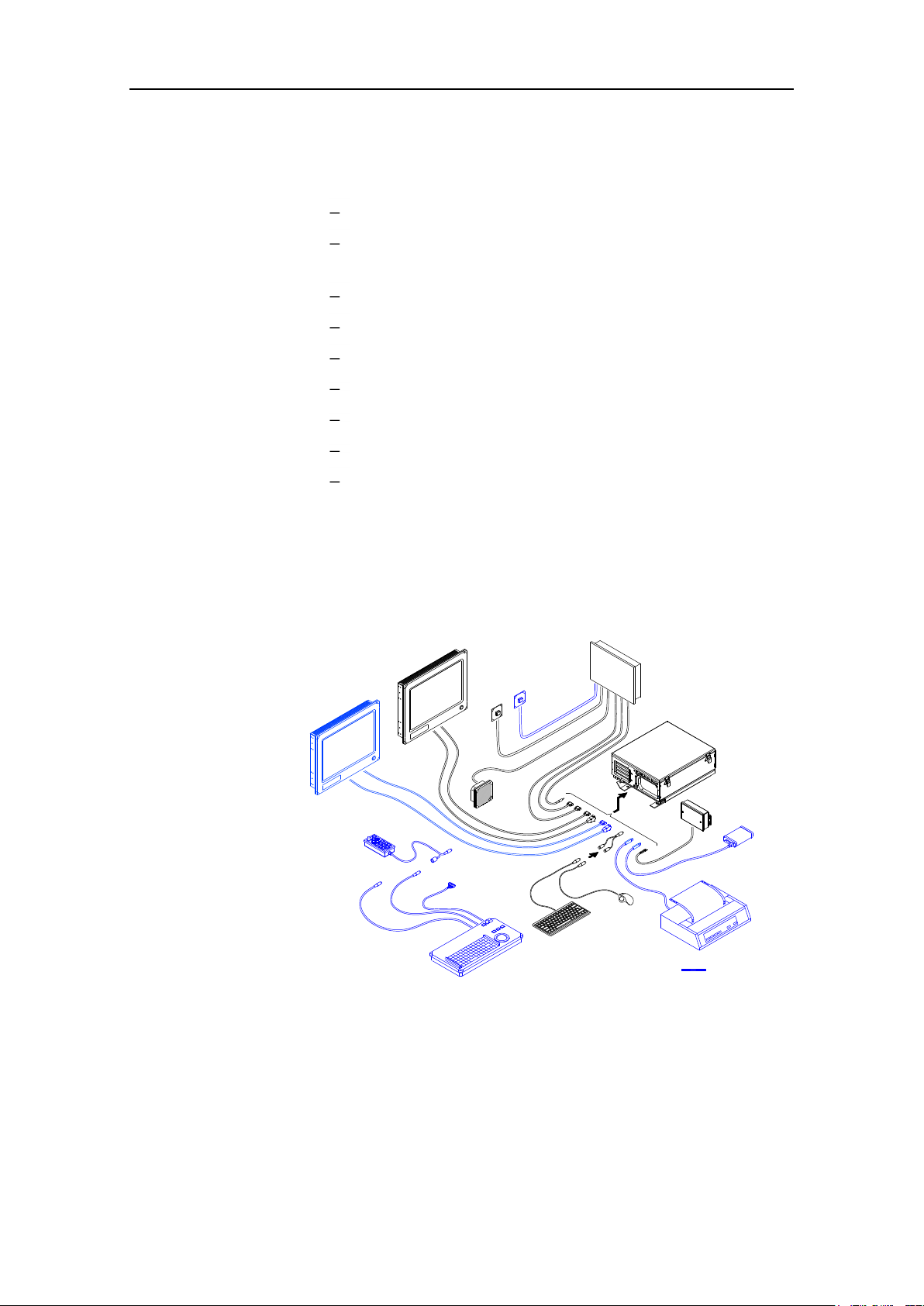
1.2 System components
OPTIONAL EQUIPMENT
A CS68 system includes the following units:
MC50 MKII Marine computer
ECDIS approved color monitor (may be delivered by
others)
FB200 Filterbox
Chart Interface unit
Cherry keyboard
Logitech TrackMan® wheel
Splitter cable for TrackMan wheel and keyboard
Loudspeaker
Alarm Reset unit
The basic system may be expanded with a second monitor, a
COP20/30 Operator panel, a COP10 remote operator panel, a
Radar Processor unit and with a printer.
INSTALLATION
If no COP20/30 is included in the system, an optional switch
may be installed to turn the system ON/OFF.
20221933 / E 3
Page 10

CS68 ECDIS
1.3 Unpacking and handling
Care should be taken when unpacking and handling the
equipment. A visual inspection should be made to see that the
equipment has not been damaged during shipment and that all
components and parts are present.
4 20221933 / E
Page 11

1.4 Location of the units
The units included in the CS68 system should be mounted with
special regard to the units’ environmental protection,
temperature range and cable length.
The CS68 units are designed to operate within the temperature
range of 0°C to +55°C. However, it is recommended that
adequate ventilation/air-conditioning is provided in order to
keep the ambient operating temperature at +20°C.
It is also recommended that the area around the units is kept
relatively free from dust and build-up static electricity.
INSTALLATION
20221933 / E 5
Page 12

CS68 ECDIS
1.5 Mechanical installation
Note Installing devices are not included with the units.
MC50 Computer
The MC50 has to be mounted horizontally, and should not be
installed close to heavy transformers or similar.
Other equipment should not be stored upon the MC50 unit.
The unit should be mounted as close as possible to the FB200
Filter box as the cable length between FB200 and MC50 is
limited to 0.45 m.
The mounting location should allow access to the power button,
the DVD and the floppy drive. It is also necessary to have
working area when replacing the air inlet fans’ dust filter.
Refer dimensional drawing showing recommended working
area, page 67 onwards.
6 20221933 / E
Page 13
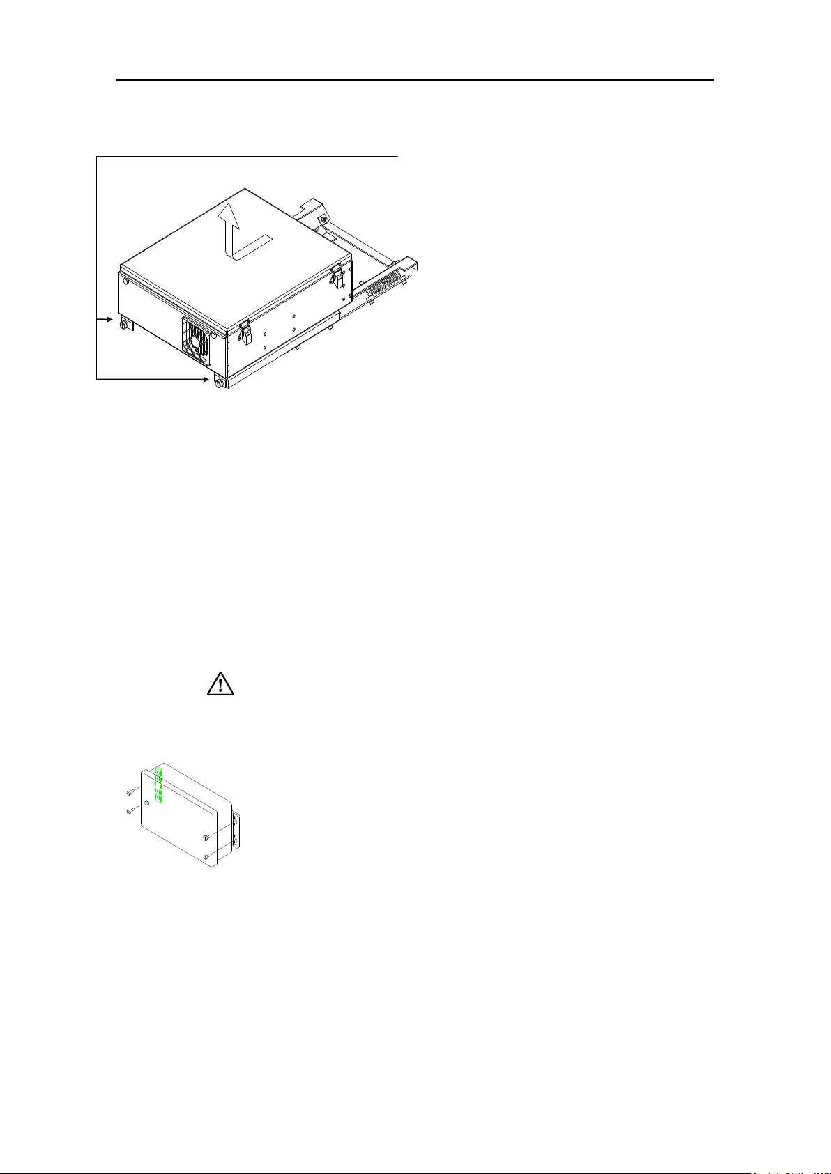
INSTALLATION
1 Loosen the 2 screws on the front of
the unit, slide the computer cabinet
1-2 cm aside, and lift the cabinet
upwards to release it from the
mounting bracket.
2 Prepare 6 holes in the deck where
the mounting bracket is to be
located. Refer dimensional
drawing, page 69.
3 Secure the mounting plate to the
deck with 6 bolts.
4 Reinstall the computer cabinet to
the mounting plate.
Monitor
One or two Hatteland Display series 1 Redesign 19”, 20.1”, 23”
and 27” monitor must be part of the ECDIS system. The
monitors must have equal size.
A separate Instruction manual is delivered with the monitor. This
manual includes installation procedures as well as dimensional
drawings.
The monitor must be validated to matrox P690 display adapter
to be ECDIS approved!
The FB200 is preferred to be mounted vertically, and should not
be installed close to heavy transformers or similar.
FB200 is secured to the bulkhead with four screws. Refer
dimensional drawing on page 72.
Use the following procedure when mounting the unit:
FB200 Filterbox
20221933 / E 7
Page 14
CS68 ECDIS
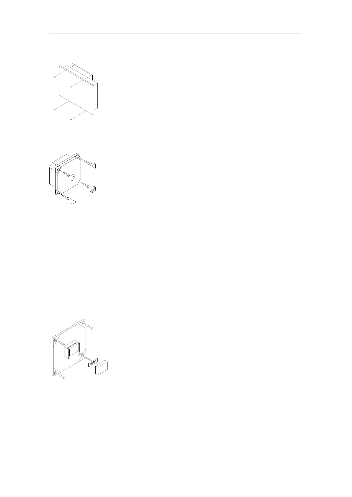
The Chart Interface unit is preferred to be mounted vertically.
Make sure that the mounting location for the unit allows for
cable entry. Refer dimensional drawing on page 73.
The Chart Interface unit is secured to the bulkhead with four
screws.
The speaker included in the CS68 system is design for panel
mounting. A mounting kit including screws and front panel
corners is included with the speaker.
1 Drill the mounting holes and make a panel cut-out
according to dimensional drawing, page 71.
2 Use the supplied screws to fasten the speaker to the panel.
3 Apply the front panel corners.
1 Fix the ECDIS or the CS68 sticker to the button. Refer
Note above.
2 Attach the lid to the button, and press firmly.
3 Drill the mounting holes according to the dimensional
drawing or drilling template on page 74 and page 81.
4 Fasten the Alarm Reset unit to the panel with the supplied
mounting screws.
Chart Interface unit
Loudspeaker
Alarm reset unit
The Alarm Reset unit is used in different chart systems, and it is
therefore delivered with different text stickers to match the
system.
Note If the Alarm Reset unit is used in an ECDIS system, the ECDIS
sticker should be used. If used in an ECDIS back-up system, the
CS68 sticker is to be used.
Use the following procedure when mounting the Alarm reset
unit:
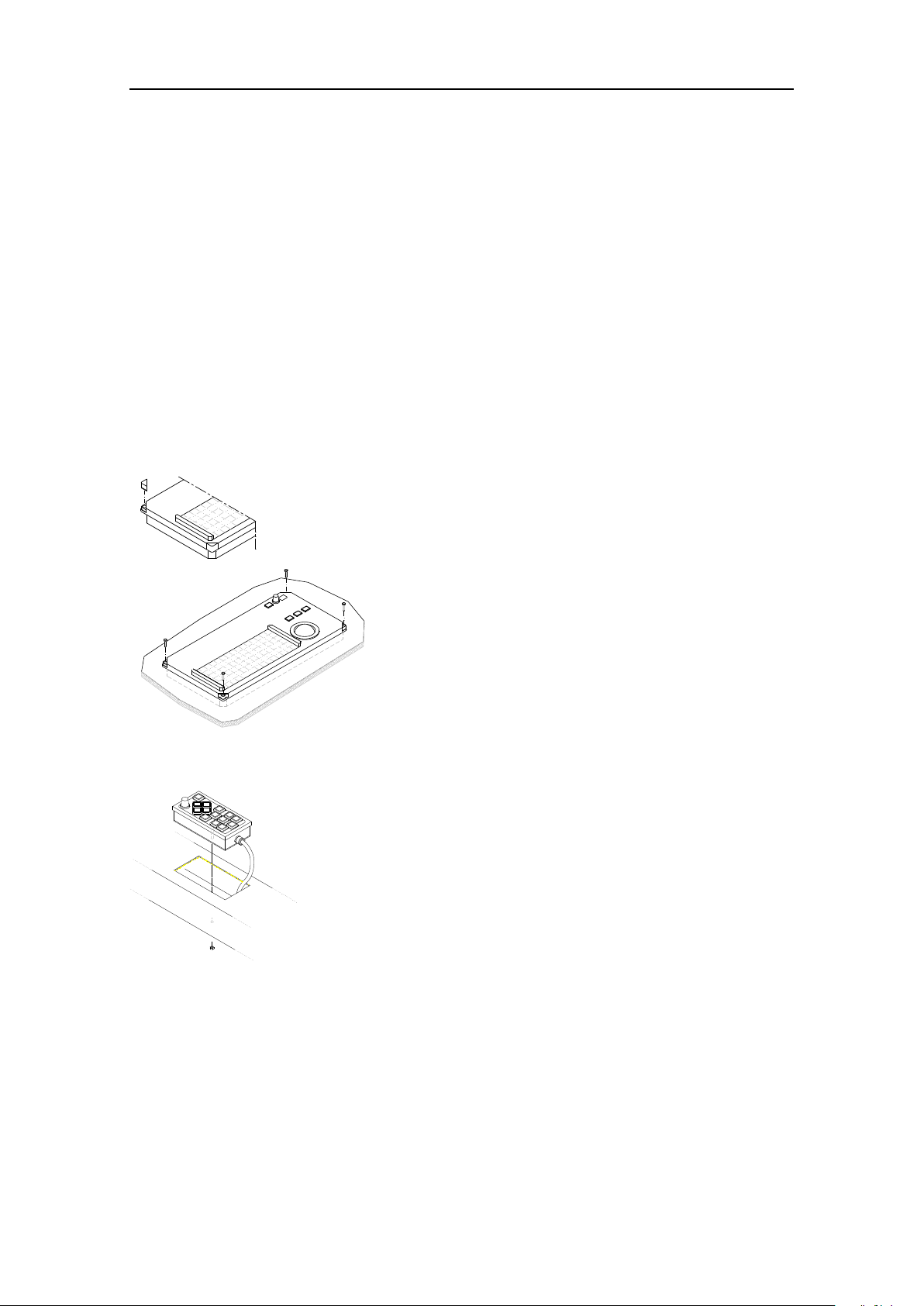
Cherry keyboard and TrackMan® wheel
The Cherry keyboard and the TrackMan wheel may be fixed to
the desk by using the included Velcro fasteners.
Note To fulfill the ECDIS regulations, the Cherry keyboard and the
TrackMan wheel must be mounted in an illuminated location!
8 20221933 / E
Page 15
INSTALLATION
1 Cut a hole where COP20/30 is to be fitted. Refer
dimensional drawing on page 76, and the cut-out
template on page 85.
2 Lift the four removable corners from the panel.
3 Locate COP20/30 in the hole, and secure the unit
to the panel with four 4mm screws.
4 Reposition the removable corners on the panel.
COP10 is designed to be mounted in the helmsman chair’s
armrest.
1 Cut the necessary holes in the armrest where COP10 is to
be fitted. Refer COP10 dimensional drawing on page 75,
and the cut-out template on page 79.
2 Secure the unit to the panel with the nut as shown on the
figure.
COP20/COP30 Operator panel (Option)
COP20/30 should be located where it is most convenient for the
user, with special regard to the user’s need for easy operation.
Refer standard and optional cable length for cables between
operating panels and MC50 unit, page 49.
It is recommended that adequate ventilation/air-conditioning is
provided in order to keep the ambient operating temperature at
+20°C.
Use the following procedure when installing the COP20/30:
COP10 Remote Operator panel (Option)
External ON/OFF switch (Option)
The optional External ON/OFF switch is secured to the panel
with four screws.
Refer dimensional drawing and drilling template on page 74 and
page 83.
20221933 / E 9
Page 16
CS68 ECDIS
GROUND
TERMINALS
1.6 Grounding the units
The computer, Chart interface unit and FB200 should have a
proper ground connection from the units’ ground terminal. The
wires should be as short as possible and have a cross section of
at least 16mm2 (gauge).
10 20221933 / E
Page 17
INSTALLATION
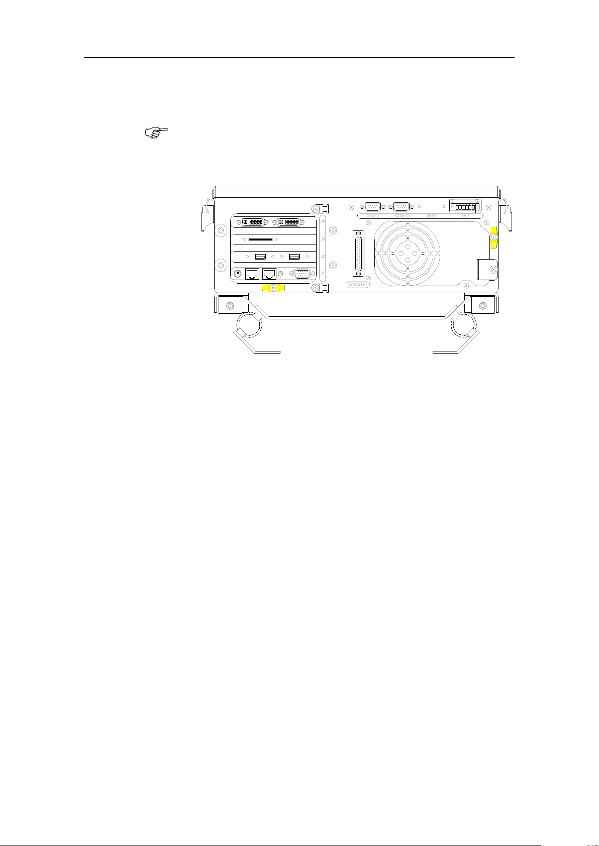
The terminal layout on your MC50 unit may differ from the illustration,
and more/less terminals may be available!
1.7 MC50 MKII computer’s terminal layout
The illustration below shows the MC50 unit’s back side.
20221933 / E 11
Page 18
CS68 ECDIS
TO
MC50 24V DC
POWER-IN
TERMINALS
GND + -
FROM
24V DC SUPPLY
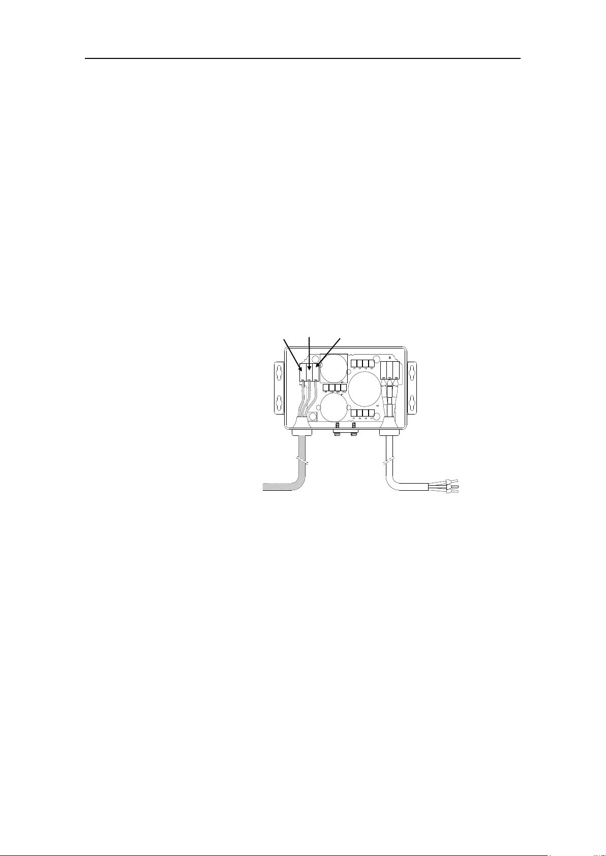
1.8 Power connection
Main power supply
CS68 system is supplied with 24V DC. The power has to be
connected via the FB200 Filter box.
Caution Do not connect 24V DC to the CS68 system without using
FB200 filter box. Doing so may course electromagnetic
interference!
1 Remove the cover on the FB200, and connect the cable
from 24V DC supply according to the labelling on the
terminals as shown on the figure below.
Note This cable is not supplied with the equipment! It should have a
cross section of at least 2.5mm2 (gauge).
2 Connect the cable from FB200 to the 24V DC power-in
jack on the MC50 computer.
3 Secure the cable to the fixing bracket to avoid that
vibration should cause the plug to loose connection.
Alarm supply
24V alarm supply from the vessel’s alarm supply has to be
connected to TB9 in the Chart Interface unit. This alarm supply
is used to activate an alarm if the main power supply to the CS
system is lost.
12 20221933 / E
Page 19

INSTALLATION
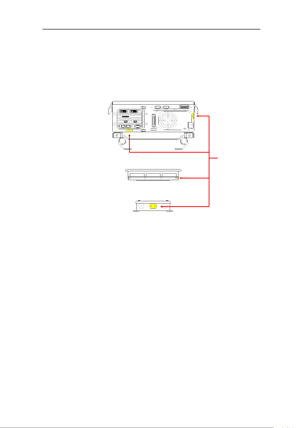
1.9 MC50/Chart Interface unit cable connections
Connections between the MC50 computer and the Chart
Interface unit are made by three cables. The cables are pre-made
from factory.
For cables lengths, refer Cabling section, page 49.
Refer also to CS68 Cabling diagram, page 77.
20221933 / E 13
Page 20

CS68 ECDIS
1.10 Connecting keyboard, mouse and speaker
Cherry keyboard and TrackMan Wheel are connected to the
MC50 computer. The speaker is connected to the Chart Interface
unit.
Note Cherry keyboard and TrackMan Wheel has to be connected via
the splitter cable.
Refer CS68 Cabling diagram, page 77.
14 20221933 / E
Page 21

1.11 Using the USB connection
If any equipment is connected to the USB port, the cable must be
equipped with one of the supplied ferrite beds (KG USB-4).
INSTALLATION
20221933 / E 15
Page 22
CS68 ECDIS
2 m
24V DC SUPPLY
COM9
MONITOR 2
COM10
2 m
J4
DVI / VGA
1.9 m
24V DC SUPPLY
MC50 MKII
PART OF
1.9 m
DVI / VGA
COMPUTER
MONITOR 1
1.12 Connecting the monitor(s)
If two monitors are used they can be used in Clone or Dual
mode.
In Clone mode both monitors display the same image.
In Dual mode the second monitor gives the operator an
additional workspace for route planning and head up display
while normal system operation is maintained on the primary
display.
It has to be decided during installation of the system if the
second monitor should be used in Clone mode or Dual mode.
Cabling
It is possible to connect 2 monitors to a CS68 ECDIS and 4
monitors to a PLECDIS
TM
system. A DVI cable is connected to
the DVI port (J4) on MC50 MKII.
A 9-pin serial cable must be connected between COM 9 or
COM 10 on MC50 MKII and the monitor(s).
If longer cable lengths are required, a high quality VGA cable
must be used together with the supplied DVI/VGA converters.
Note Do not use the VGA output on J1 on the rear of MC50 MKII.
According to Simrad CS68 ECDIS certificate only DVI ports on
J4( can be used to connect one or two ECDIS compliant
Hatteland series 1 RD monitors.
Display configuration
The system is pre-configured to use 2 JH 19T14 MMD, and to
use these in Clone mode.
The following monitors from Hatteland Display are supported:
JH19T14 MMD (1280*1024 – 60 Hz)
JH20T17 MMD (1600*1200 – 60 Hz)
16 20221933 / E
JH23T12 MMD (1600*1200 – 60 Hz)
JH27T11 MMD (1920*1200 – 60 Hz)
Page 23

INSTALLATION
The support site is authorized for OEM, dealers and distributors. A
password is required to get access to this web site.
To configure these alternative monitors and change from Clone
to Dual mode the additional ECDIS Admin tool must be used.
This sw must be downloaded from Simrad’s support site
(http://www.simrad-yachting.com/en/Support/).
The selected COM port(s) need to be defined in the System
Configuration dialog to make sure that automatically backlight
adjustment are done according to ECDIS regulations.
Refer Output configuration, page 37.
20221933 / E 17
Page 24
CS68 ECDIS
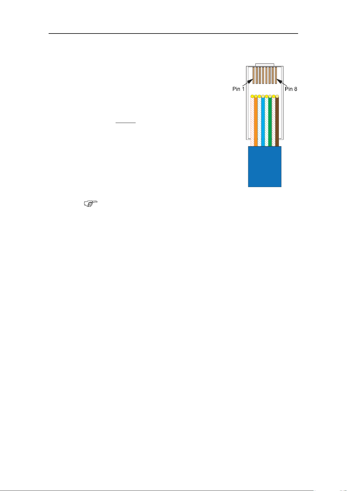
The CS68 system can be connected to
Internet to utilize online chart update.
The system is connected by using a
shielded Ethernet cable.
NOTE:
Pin 1 and 3 or pin 2 and 6 must be
broken!
To fulfill the ECDIS requirements the system must be connected via
a switch that electrically separates the ECDIS from the Internet!
1.13 Connecting the system to Internet
The Ethernet cable must be equipped with one of the supplied
ferrite beds (SFC-10).
18 20221933 / E
Page 25
1.14 Connecting optional equipment
(OPTION)
COP20/30 5 m
KEYBOARD
MOUSE
(OPTION)
ON/OFF SWITCH
5 m
2
ALARM RTN
GREEN
(6)
GREY
YELLOW
PINK
(4)
(5)
(3)
5
+12V
GND
6
ON +
ON -
4
3
BROWN
WHITE
(1)
(2)
YELLOW
GREEN
(6)
(5)
TB15
ALARM
1
RED
NC
(3)
NC
CHART INTERFACE UNIT
1.5 m
1.7 m
0.2 m
PS2 (J1)
1.6 m
1.8 m
5 m
PART OF MC50
COP10
(OPTION)
PART OF
(4)
BLUE
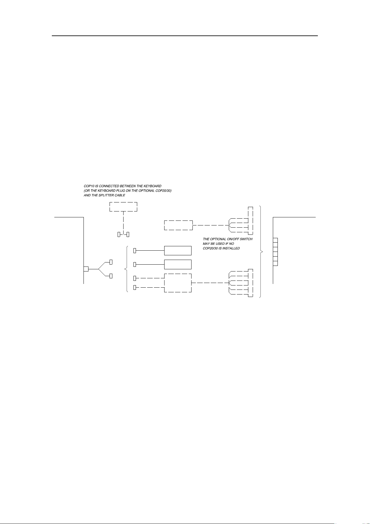
If a COP20 or COP30 is to replace the Cherry keyboard and the
TrackMan Wheel, the keyboard and mouse cable on COP20/30
are connected to the computer’s PS2 port by using the splitter
cable.
COP20/30’s signal cable is connected to TB15 in the Chart
Interface unit.
If an optional COP10 is to be used in the chart system, this unit
is connected between the keyboard (or the keyboard plug on
COP20/30) and the splitter cable as shown on the figure below.
If no COP20/30 is installed, an optional ON/OFF switch may be
connected to TB15 in the Chart Interface unit.
INSTALLATION
Standard cable length for all optional units are shown on page
49.
20221933 / E 19
Page 26

CS68 ECDIS
THIS PAGE INTENTIONALLY
LEFT BLANK
20 20221933 / E
Page 27

CONNECTING EXTERNAL EQUIPMENT
2 CONNECTING EXTERNAL EQUIPMENT
This section described how external equipment is connected to
the CS68 system.
20221933 / E 21
Page 28

CS68 ECDIS
2.1 General
All external equipment is connected to the CS68 system via the
Computer Interface board in the Chart Interface unit. Component
layout showing terminals, strap location and diodes on this
board is shown on page 78.
Connect the signal cabling from the external equipment as per
the manufacturer’s specification and according to the description
in the following pages.
22 20221933 / E
Page 29

CONNECTING EXTERNAL EQUIPMENT
PIN NO.
SIGNAL NAME
COMMENTS
1
RX +
NMEA channels
1 to 8
2
RX -
3
TX +
4
TX -
5
GND
Four LEDs for each of the eight I/O channels are
indicating signals passing the channels by steady,
interrupting or flashing lights as shown in the table
below:
LED
LED STATUS
COMMENTS
Tx-
Interrupting
Transmitting data
Steady
No data transmitted
Tx+
Flashing
Transmitting data
Off
No data transmitted
Rx-
Interrupting
Receiving data
Steady
No data received
Rx+
Flashing
Receiving data
Off
No data received
2.2 Serial I/O ports (TB1 – TB8)
Signal description
LED indication
20221933 / E 23
Page 30

CS68 ECDIS
PIN NO.
SIGNAL NAME
COMMENTS
1
In +
Digital input 1
Shortcut 0,5 sec. to
silence all alarms
2
In -
3
In +
Digital input 2
(Spare)
4
In - 5 In +
Digital input 3
(Spare)
6
In -
2.3 Digital Input ports (TB10)
Signal description
LED indication
There are no LEDs for the Digital Input ports.
24 20221933 / E
Page 31

CONNECTING EXTERNAL EQUIPMENT
PIN NO.
SIGNAL NAME
COMMENTS
1
Out +
Digital Output 1
System Failure
Signal high: Standard mode
Signal low: System failure (ECDIS
shut down)
2
Out -
3
Out +
Digital Output 2
Alarm sound control
Signal low: No audible alarm/or alarm
muted
Signal high: Audible alarm present
4
Out -
5
Out +
Digital Output 3
Alarm present on ECDIS
Signal low: No alarm present
Signal high: Alarm present
Acknowledge of alarms does not
change the signal.
6
Out -
DIGITAL
OUTPUT 1
DIGITAL
OUTPUT 2
DIGITAL
OUTPUT 3
Normally open
Normally closed
(Factory default)
LED
LED STATUS
COMMENT
D16 (Output 1)
ON
Relay active
D18 (Output 2)
D56 (Output 3)
2.4 Digital Output ports (TB11)
Signal description
Strap settings for inverting signals
The digital output is 24V, determined by the strap settings on S1
– S3 as shown in the table below:
LED Indication
D16, D18 and D56 are used to indicate active relay on digital
output ports as indicated in the table below.
20221933 / E 25
Page 32

CS68 ECDIS
Each cable screen should be properly terminated to the Chart
Interface unit’s grounding bar as follows:
1 Strip the cable’s insulation and pull the screen backward
to cover the insulation.
2 Fix the cable screen to the grounding bar by a wire
strap. Tighten well to make sure the screen has good
contact.
2.5 Grounding external cables
26 20221933 / E
Page 33

CONNECTING EXTERNAL EQUIPMENT
If the radar video is not referenced to CCRP, the offset should be set
in the Radar position offset field in the Radar menu (Tools/Radar).
2.6 Connection of Radar processor unit
The Radar Processor unit is connected by the USB cable to a
spare USB connector on the MC50 Mk2. For connection to the
vessel radar system, refer to separate manual.
20221933 / E 27
Page 34

CS68 ECDIS
3 SOFTWARE CONFIGURATION
This section describes how to configure the CS68 software.
28 20221933 / E
Page 35

SOFTWARE CONFIGURATION
1 Press the Setup menu, followed by the System
Configuration command.
A dialog will request a password before it is possible to
enter the system configuration.
3.1 The System configuration dialog
All configuration of the CS68 system is done from the System
Configuration dialog. This dialog is the entrance to all settings
that have to be done when configuring the system.
Note The following pages list the settings as they appear in the
dialogs. All these settings have to be performed before the CS
system is ready for operation.
To avoid unintended alteration of system parameters, the
System Configuration dialog is password protected.
Use the following procedure to open the System Configuration
dialog:
2 Type “1234” in the Password field, and confirm the entry
with the OK button.
The Input tab in the System Configuration dialog will
now be displayed.
20221933 / E 29
Page 36

CS68 ECDIS
Ref page:
Inputs:
Used to configure external devices.
32
Outputs:
Used for configuring the output format.
37
Checksum:
Used for checksum test for received data.
38
Aux settings:
Used for different hardware and software settings.
39
Misc:
Used for different operator parameters.
40
Ship:
Used for defining the ship size.
42
Note Data entered in the System Configuration dialog are not taken
into account until it is confirmed by clicking the OK or APPLY
buttons:
OK: changes are applied, and the dialog box is removed from
the display
APPLY: changes are applied, and the dialog box remains
displayed.
The different tabs in the System Configuration dialog are
described in the following pages.
30 20221933 / E
Page 37

3.2 Input configuration
The Inputs tab in the System Configuration dialog is used for
configuring the input format for each interfacing serial channel.
The tab is also used to delete or edit an already defined input.
All defined input devices are listed alphabetically in the Input
tab. If no input device is configured, the dialog will be empty.
SOFTWARE CONFIGURATION
20221933 / E 31
Page 38

CS68 ECDIS
New devices are configured by pressing the New button when
the Inputs tab in the System Configuration dialog is active.
The Input Config dialog is displayed.
Device Name
Name for the input device. The device name is limited to 8 characters.
The entered name will be displayed in the different user menus and will
also be used in an alarm text.
Input Source
Com. port used for the device.
Device Type
Drop down field with available device types.
Data Format
NMEA format and Baud Rate for the device. Available alternatives are
dependant on selected device type.
Baud Rate
NMEA Header
NMEA header for the device. This header must be specified if multiple
talkers with identical telegram type (e.g. GLL) are connected.
Listen for
Selectable sentences for the device. Available sentences may be
displayed by pressing the Monitor Serial line button. Refer page 36.
The following sentences is preferred for GPS: GGA, VTG, ZDA and
DTM
Time Out in Seconds
Time-out limit for the data. If the data stops and is not received within
the specified time-out limit, an alarm will be activated.
Adding new device
Note Which data that is available in the Input Config dialog depends
on which device type that is selected.
The Input Config dialog has the following fields:
Note If data-transmitting rate is low, e.g. ARPA or some echo
sounders, a short time-out may block the data.
32 20221933 / E
Page 39

SOFTWARE CONFIGURATION
Navigator Datum
Specification for differential GPS. Must be entered if Navigator or AIS
is selected as device type.
Valid flag
Antenna position
offset from ref. point
Values for antenna offset for Navigator and AIS devices.
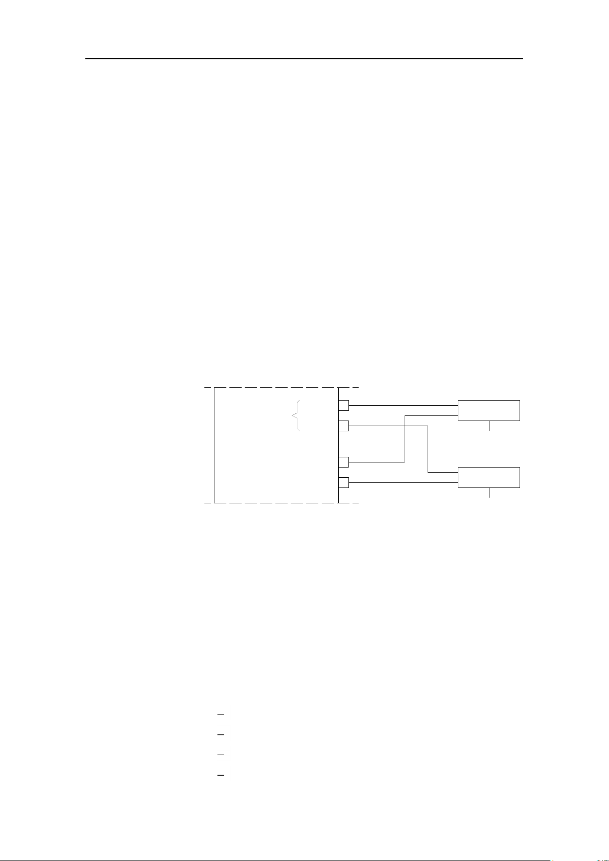
If two equal navigators (GPS) with antennas are installed as indicated
on the figure below, and if correct antenna offset is entered, there
should be no position difference between them. The ship will obtain
the same position in the chart even if the sensors are exchanged!
If an ARPA/MARPA is connected to the CS system in order to receive
ARPA targets, the targets have to be correctly referenced to the CCRP
(no internal offset required).
x
y
0,0
ANTENNA POSITION (+X, +Y)
ANTENNA POSITION (-X, -Y)
All sensors refer to the vessel’s reference point. This point is
defined in Ship settings, page 42. If no reference is defined, the
vessel’s center of gravity will be used as reference point.
If the antennas are mounted out of the reference point, the offset
x and y values for the antenna position must be entered into the
system to give the correct ship position.
The position for a GPS is the position of the antenna. The
position is given as an x and y offset relative to the vessel center,
with positive value forward and to starboard.
20221933 / E 33
Page 40

CS68 ECDIS
By pressing the Advanced button when the Inputs tab in the
System Configuration dialog is active, the Advanced Input
Settings dialog is displayed.
Advanced input settings
This dialog is used for advanced settings for ARPA, log, gyro,
position reference sentences and Ethernet connection.
All tabs in this dialog have text specifying the different data
fields as shown in the “arp” tab shown below.
Modifying an input device
A device can be modified by pressing the Edit button, or by
double-clicking the specific device in the Inputs tab in the
System Configuration dialog. The Input Config dialog will be
displayed, and parameters modified as described on page 32
onwards.
34 20221933 / E
Page 41

SOFTWARE CONFIGURATION
Deleting an input device
A defined input device is deleted by activating the device in the
Inputs tab, and then pressing the Delete button.
To avoid unintended removal of a device, the selection has to be
confirmed by pressing the OK button.
20221933 / E 35
Page 42

CS68 ECDIS
The Monitor Serial Line button in the Input tab in the System
Configuration dialog makes it possible to monitor each serial
line individually.
Close:
Closes the dialog and returns the display to the Inputs tab in the
System Configuration dialog.
Freeze:
Stops the text from scrolling.
Clear:
Clears the text field in the dialog.
Hex/ASCII:
Toggles the log data between hexadecimal and ASCII characters.
Log Activate:
Saves the monitored log data to a file.
A new dialog for selecting file name and location will be displayed.
When logging is activated, the button will change to Log
Deactivate. Pressing this button will stop logging data to file.
Select font:
Used for changing font for the text.
Monitoring a serial line
The buttons in the dialog are used as follows:
36 20221933 / E
Page 43

3.3 Output configuration
Output line
Drop down field for selecting serial output line to be specified.
Minimum baudrate
Value increasing as output messages are selected. Note that this value
not should exceed the value set for the input baudrate on the same
com. line.
Clear
Clear all selected output message sentences.
Output messages
Available sentences for the output device. The output is NMEA0183
Standard sentences, and at least one of these sentences must be
enabled.
Output line for
controlling monitor
Used to define which COM port used for the monitors
Serial output format are configured from the Outputs tab in the
System Configuration dialog.
SOFTWARE CONFIGURATION
The following fields are available:
20221933 / E 37
Page 44

CS68 ECDIS
Max Sequential
Checksum Errors
Number of sequential checksum errors detected before a checksum alarm
will be given.
3.4 Checksum
NMEA data sent to the CS system may contain a checksum.
When the CS system receives data with checksum included, it
will automatically calculate the checksum and compare this sum
with the checksum transmitted by the device.
When the calculated and the received checksum not are
identical, the settings in the Checksum tab in the System
Configuration dialog will decide whether the CS system will
use or reject these data.
Each serial line has its own checksum configuration.
38 20221933 / E
Page 45

3.5 Auxiliary settings
Screen decimals
Number of decimals displayed for the position reference in the Position
Window. In the example below, 4 decimals are selected.
NMEA decimals
Number of decimals used in the data output sentences.
Stepper Gyro
Not used.
Voice Alarm
Toggles voice alarm function ON/OFF.
Start Route
Replication
Enables route replication between ECDIS and Backup machine in PLECDIS
configurations. Routes created on one system will then automatically be
copied to the other system.
SOFTWARE CONFIGURATION
20221933 / E 39
Page 46

CS68 ECDIS
Time Zone
Time zone according to UTC. The system will read the UTC time from the
GPS and update it to local time.
Screen size
Used for setting correct diagonal screen size. When pressing the Start
RULER button, a new dialog for entering screen size is opened.
Press the Measure the Screen button to open a new dialog used
for measuring a selected area directly on the monitor.
Measure width and height of the white area and enter the values in
inches of mm.
3.6 Miscellaneous settings
40 20221933 / E
Page 47

SOFTWARE CONFIGURATION
Alarm Test
By pressing this button, the built in alarm system will issue an alarm for 5
seconds.
Backup Manager
Used for starting the backup manager. Refer the separate CS68 Operator
Manual.
Clean all registry
settings
Cleans all registry settings when the system is shut down. This will force the
system to use default values for all system variables.
Display units
Units of measurement for speed, depth, temperature and distance.
Caution The Screen size MUST be set correctly to display the correct
chart scale and to place targets correctly in the chart. If the
screen size is wrong AIS target in the outer end of the screen
area will be positioned incorrectly.
After Screen size has been adjusted the chart system must be
restarted to synchronize the screen settings.
Caution This action will remove all configured devices.
20221933 / E 41
Page 48

CS68 ECDIS
Ship name
Parameters used when transmitting AIS information.
These fields should be entered correctly to ensure that
correct information will be used in the AIS system.
Type of ship
Type of cargo/operation
MMSI
IMO
Call Signal
Measurements
Parameters used by the CS system to draw a ship symbol
in true size. Used when the actual ship is larges that the
minimum ship symbol.
Note that the reference offset points are calculated from
the vessel’s center point.
Turn Radius
Used as default value when a route is created.
Crab Factor
Used for autopilot turn start calibration.
Wheel over time
Response time (in seconds) from a rudder command is
given until the vessel starts turning. This parameter is
dependant on vessel characteristics, and it could be
necessary to change the value when the vessel is heavily
loaded.
Max Speed
Used as max value for speed entries.
3.7 Ship settings
42 20221933 / E
Page 49

INSTALLATION APPROVAL
4 INSTALLATION APPROVAL
This section includes check lists that should be used to
verify correct installation of the CS68 system.
20221933 / E 43
Page 50

CS68 ECDIS
4.1 General
When all units are installed, external equipment connected and
the software configured according to the previous sections, the
installation should be verified according to the check lists in the
following pages.
44 20221933 / E
Page 51

4.2 Check lists
Procedure
Ref.
page
Y N NA
Comment
All units mounted as described:
MC50 computer
6
Monitor 1
7
Monitor 2
7
FB200 Filterbox
7
Chart Interface unit
8
Loudspeaker
8
Alarm Reset unit
8
Optional operator panels
9
Optional External
ON/OFF switch
9
Units properly grounded
10
Procedure
Ref.
page
Y N NA
Comment
Power connected to MC50
12
Alarm supply connected to TB9
in Chart Interface unit
12
Mechanical installation
INSTALLATION APPROVAL
Power connection
20221933 / E 45
Page 52

CS68 ECDIS
Procedure
Ref.
page
Y N NA
Comment
Keyboard and mouse
connected via splitter cable to
PS2 port (J1) on MC50
14
Monitor cables connected to
monitor plug (J4) and to COM9
or COM10 on MC50
14
Speaker connected to TB13 in
Chart Interface unit
Refer cabling diagram, page 77
Internal cables connected from
MC50 to Chart Interface unit:
Audio Out (J1) on MC50
to TB14
on Chart Interface unit
TB1 on MC50
to TB16
on Chart Interface unit
J3 on MC50
to J1
on Chart Interface unit
Optional external ON/OFF
switch connected to TB15 in
Chart Interface unit
Optional operator panels
connected to MC50 (and Chart
Interface unit)
18
Procedure
Ref.
page
Y N NA
Baud
Rate
Type of equipment / Sentence
External equipment connected
to input/output ports in Chart
Interface unit:
TB1 (Serial I/O port)
23
Input:
Output:
TB2 (Serial I/O port)
Input:
Output:
TB3 (Serial I/O port)
Input:
Output:
TB4 (Serial I/O port)
Input:
Output:
TB5 (Serial I/O port)
Input:
Output:
Internal cabling
External equipment
46 20221933 / E
Page 53

INSTALLATION APPROVAL
Procedure
Ref.
page
Y N NA
Baud
Rate
Type of equipment / Sentence
TB6 (Serial I/O port)
23
Input:
Output:
TB7 (Serial I/O port)
Input:
Output:
TB8 (Serial I/O port)
Input:
Output:
TB10 (Digital input)
24
TB11 (Digital output)
25
Procedure
Ref.
page
Y N NA
Comment
Minimum reference systems
configured:
GPS
32
GPS datum
33
GPS Antenna offset
33
Gyro
32
Log
32
Display units selected
41
Screen size set correctly
40
Ship information and
parameters entered
42
Procedure
Ref.
page
Y N NA
Comment
Alarms operational
41
Time updated correctly from
GPS
40
Keyboard and mouse operative
Procedure
Ref.
page
Y N NA
Comment
Back-up made to Library and
burned to DVD after system
configuration is completed
Described in the separate CS68
Operator Manual
Software configuration
20221933 / E 47
General check
System back-up
Page 54

CS68 ECDIS
5 TECHNICAL SPECIFICATIONS
This section lists hardware specification for all units
included in the CS68 system.
48 20221933 / E
Page 55

5.1 Cabling
20
OPTIONAL EQUIPMENT
1
8
9
7
19
3
2
4
14
13
15
6
5
12
16
17
18
10
11
TECHNICAL SPECIFICATIONS
Cable length for standard and optional units in the CS68 system
is shown on the figure below and in the table on next page.
20221933 / E 49
Page 56

CS68 ECDIS
CABLE NO.
CABLE LENGTH
DESCRIPTION
1
0.45 m
Part of FB200
2
0.2 m
Splitter cable
3
1.8 m
Part of TrackMan wheel
4
1.6 m
Part of Cherry keyboard
5
5 m
Alarm reset
6
8.5 m
Part of speaker
7
1.25 m
(J3 MC50 – J1 Chart Interface unit)
8
1.25 m
(TB1 MC50 – TB16 Chart Interface unit)
9
1.3 m
Audio
10
-
Supplied with monitor (may be delivered
by others
11 - 12
5 m
Part of external ON/OFF switch
13
5.0 m
(System)
Part of COP20/COP30
14
1.5 m
(Keyboard)
15
1.7 m
(Mouse)
16
5 m
Part of COP10
17
-
Supplied with monitor (may be delivered
by others)
18
-
19
Ordered from printer supplier
20
TBA
Part of Radar Processor unit
50 20221933 / E
Page 57

5.2 MC50 computer unit
Height: ............................................................................. 196 mm
Width: .............................................................................. 363 mm
Depth: .............................................................................. 428 mm
Net weight ........................................................................... 9.5 Kg
Color: ................................................................................... Black
Environmental Protection: ..................................................... IP22
Temperature range:
Operating: ........................... 0 to +55 °C (+32 to +131 °F)
Storage: ............................. –15 to +70 °C (+5 to +158 °F)
Dimensional drawing: ........................................ page 67 onwards.
TECHNICAL SPECIFICATIONS
20221933 / E 51
Page 58

CS68 ECDIS
5.3 Loudspeaker
Height: ............................................................................. 110 mm
Width: .............................................................................. 110 mm
Depth: ................................................................................ 48 mm
Color: ................................................................................... Black
Effect (PMPO): .......................................................... 80 watt max
Frequency range: ................................................... 20Hz – 80 kHz
Environmental Protection: ..................................................... IP22
Dimensional drawing: ....................................................... page 71
52 20221933 / E
Page 59

5.4 FB200 Filterbox
Height: ............................................................................... 50 mm
Width: .............................................................................. 177 mm
Depth: .............................................................................. 103 mm
Net weight: .......................................................................... 0.5 Kg
Power: .............................................................................. 24V DC
Power consumption ............................................................. 140W
Color: ................................................................................... Black
Environmental Protection: ..................................................... IP32
Temperature range:
Operating: ........................... 0 to +55 °C (+32 to +131 °F)
Storage: ............................. –15 to +70 °C (+5 to +158 °F)
Dimensional drawing: ...................................................... page 72.
TECHNICAL SPECIFICATIONS
20221933 / E 53
Page 60

CS68 ECDIS
5.5 Chart Interface unit
Height: ............................................................................. 280 mm
Width: .............................................................................. 312 mm
Depth: ................................................................................ 60 mm
Net weight: .......................................................................... 2.3 Kg
Power: .............................................................................. 24V DC
Power consumption ............................................................... 50W
Color: ................................................................................... Black
Environmental Protection: ..................................................... IP22
Temperature range:
Operating: ........................... 0 to +55 °C (+32 to +131 °F)
Storage: ............................. –15 to +70 °C (+5 to +158 °F)
Dimensional drawing: ...................................................... page 73.
54 20221933 / E
Page 61

5.6 Cherry keyboard
Height: ............................................................................. 130 mm
Width: .............................................................................. 280 mm
Depth: ................................................................................ 37 mm
Net weight ........................................................................... 0.5 Kg
Color: ................................................................................... Black
Temperature range:
Operating: ............................. 0 to +55°C (+32 to +131°F)
Storage: ............................... –15 to +70°C (+5 to +158°F)
Dimensional drawing: ....................................................... page 70
TECHNICAL SPECIFICATIONS
20221933 / E 55
Page 62

CS68 ECDIS
5.7 TrackMan wheel
Height: ............................................................................. 145 mm
Width: ................................................................................ 90 mm
Depth: ................................................................................ 58 mm
Net weight: .......................................................................... 0.2 Kg
56 20221933 / E
Page 63

5.8 Alarm Reset unit
Height: ............................................................................... 72 mm
Width: ................................................................................ 72 mm
Depth, including cable bend: ............................................. 70 mm
Net weight: ............................................................ 0.35 Kg
Dimensional drawing: ....................................................... page 74
TECHNICAL SPECIFICATIONS
20221933 / E 57
Page 64

CS68 ECDIS
5.9 COP20/COP30 Operator panel (Option)
Height: ............................................................................. 220 mm
Width: .............................................................................. 440 mm
Depth: .................................................... 135 mm incl. cable bend
Net weight ........................................................................... 3.8 Kg
Color: ................................................................................... Black
Illumination:................................................................. Adjustable
Environmental Protection: ..................................................... IP56
Temperature range:
Operating: ........................... 0 to +55 °C (+32 to +131 °F)
Storage: ............................. –15 to +70 °C (+5 to +158 °F)
Dimensional drawing: ...................................................... page 76.
58 20221933 / E
Page 65

TECHNICAL SPECIFICATIONS
5.10 COP10 Remote Operator panel (Option)
Height: ............................................................................. 144 mm
Width: ................................................................................ 72 mm
Depth: ................................................ 76 mm incl. securing screw
Net weight ......................................................................... 0.65 Kg
Color: ................................................................................... Black
Enclosure material: ...................................................... Aluminum
Mounting: .............................................................. Panel mounted
Environmental Protection: ..................................................... IP32
Temperature range:
Operation: .......................... 0 to +55 °C (+32 to +131 °F)
Storage: ............................. –15 to +70 °C (+5 to +158 °F)
Dimensional drawing: ...................................................... page 75.
20221933 / E 59
Page 66

CS68 ECDIS
5.11 External ON/OFF switch (Option)
Height: ............................................................................... 72 mm
Width: ................................................................................ 72 mm
Depth, including cable bend: ............................................. 70 mm
Net weight: ........................................................................ 0.35 Kg
Dimensional drawing: ....................................................... page 74
60 20221933 / E
Page 67

6 SPARE PART LISTING
This section includes part numbers for all standard and optional
units that may be included in a CS68 system.
SPARE PARTS LISTING
20221933 / E 61
Page 68

CS68 ECDIS
PART NUMBER DESCRIPTION
000-00004-001
MC50 MKII Computer
000-00019-001
JH19T14 MMD (1280*1024 – 60 Hz)
TBA
JH20T17 MMD (1600*1200 – 60 Hz)
TBA
JH23T12 MMD (1600*1200 – 60 Hz)
TBA
JH27T11 MMD (1920*1200 – 60 Hz)
26055046
FB200 Filterbox
26056200
Chart Interface unit
44176022
Cherry keyboard
44169712
TrackMan wheel
26056218
Loudspeaker
26056473
Alarm reset unit
26053231
COP10 Remote operator panel
26053355
COP20 Operator panel
26053207
COP30 Operator panel
26056713
External ON/OFF switch
TBA
Radar Processor unit
6.1 Main components
62 20221933 / E
Page 69

6.2 Accessories
PART NUMBER
DESCRIPTION
44142131
Air inlet filter
SPARE PARTS LISTING
20221933 / E 63
Page 70

CS68 ECDIS
64 20221933 / E
Page 71

7 DRAWINGS
This section includes drawings, diagrams and cut-out
templates for units in the CS68 system.
DRAWINGS
20221933 / E 65
Page 72

CS68 ECDIS
Name
Drw.no
Rev.
MC50 Dimensional drawing (3 pages)
- Front view page 67
- Side view page 68
- Bottom view page 69
D3-605555
A
Cherry keyboard. Dimensional drawing
N4-081309
-
Loudspeaker. Dimensional drawing
N3-605618
A
Chart Interface unit. Dimensional drawing
N1-605617
A
Alarm Reset unit / External ON/OFF switch.
Dimensional drawing
D4-605650
A
FB200, dimensional drawing
D3-604913
A
COP10 (OPTION). Dimensional drawing
N3-605303
A
COP20/COP30 (OPTION). Dimensional drawing
N1-605304
A
CS68 Chart system, Cabling diagram
N3-605644
C
Computer interface board, component layout
N4-605514
D
Loudspeaker, Panel cut-out
N4-605619
A
Alarm Reset unit / External ON/OFF switch.
Panel cut-out
D4-605650
A
COP10, Panel cut-out
N3-605303
A
COP20/30, Panel cut-out
N1-605304
A
7.1 Drawings overview
Parts of the following drawings are enclosed:
Note The original signed drawings are recorded at Navico Egersund.
66 20221933 / E
Page 73

7.2 MC50 Marine Computer
Front view
DRAWINGS
20221933 / E 67
Page 74

CS68 ECDIS
Side view
68 20221933 / E
Page 75

Bottom view
DRAWINGS
20221933 / E 69
Page 76

CS68 ECDIS
7.3 Cherry keyboard
70 20221933 / E
Page 77

7.4 Loudspeaker
DRAWINGS
20221933 / E 71
Page 78

CS68 ECDIS
7.5 FB200 Filter box
72 20221933 / E
Page 79

7.6 Chart Interface unit
DRAWINGS
20221933 / E 73
Page 80

CS68 ECDIS
7.7 Alarm Reset unit / External ON/OFF switch
74 20221933 / E
Page 81

7.8 COP10 (Option)
DRAWINGS
20221933 / E 75
Page 82

CS68 ECDIS
7.9 COP20/COP30 (OPTION)
76 20221933 / E
Page 83

DRAWINGS
PS2
12345
6
ETHERNET
ETHERNET
AUDIO OUT
DVI / VGA
GND
+
-
GND
+
-
FROM 24V DC SUPPLY
+
-
GND
24V DC
MC50 MKII COMPUTER
MONITOR 1
FB200 MC FILTERBOX
SPEAKER
J1
FOR
CONNECTION
TO EXTERNAL
EQUIPMENT
J3
USB2
PARALLEL
CHART INTERFACE UNIT
1
2
TB14
AUDIO OUT
2
TB13
1
COP20/30
342
TB15
1
1
2
TB12
24V
2
1
TB9
56342
TB11
1
56342
TB10
1
DIGITAL
INPUT
DIGITAL
OUTPUT
-
+
PRE-HEAT
-
ALARM
+
24V
1
2
3
132
TB1
NC
NC
GND
ON -
ON +
+12V
(OPTION)
COP10
MOUSE
KEYBOARD
(OPTION)
5 m
5 m
1.6 m
1.5 m
1.7 m
1.8 m
0.2 m
1.3 m
8.5 m
1.25 m
1.25 m
0.45 m
-
+
+
-
-
+
1.9 m
1
2
TB17
3
4
SWITCH +
LAMP +
SWITCH -
LAMP -
ALARM RESET
5 m
-
+
+
-+-
65432
1
(6)
GREEN
YELLOW
(3)
PINK
GREY
(5)
(4)
BROWN
WHITE
(2)
(1)
RED
BLACK
BLACK
RED
2
56341
(3)
RED
BLUE
(4)
YELLOW
GREEN
(2)
(1)
GND
ALARM RTN
ON -
+12V
TX+
GND
TX-
RX+
RX-
4
5
123
TB1
TX-
4
GND
5
RX-
TX+
RX+
123
TB2
TX-
4
GND
5
RX-
TX+
RX+
123
TB3
TX-
4
GND
5
RX-
TX+
RX+
123
TB4
TX-
4
GND
5
RX-
TX+
RX+
123
TB5
TX-
4
GND
5
RX-
TX+
RX+
123
TB6
TB7
GND
TX+
RX+
RX-
TX-
5
4
213
TX-
RX-
RX+
TX+
GND
345
1
2
TB8
J1
AUDIO IN
SERIAL
LINE
NO.1
NO.2
LINE
SERIAL
NO.3
LINE
SERIAL
NO.4
LINE
SERIAL
NO.5
LINE
SERIAL
NO.6
LINE
SERIAL
NO.7
LINE
SERIAL
NO.8
LINE
SERIAL
TB16
56342
1
5
6
ON +
ALARM
NC
+12V
GND
ON +
ON -
NC
2 m
24V DC SUPPLY
ON/OFF SWITCH
5 m
RED
(3)
BLUE
(4)
GREEN
(6)
YELLOW
(5)
(OPTION)
NC
NC
MONITOR
(NOT USED)
COM9
MONITOR 2
COM10
2 m
J4
DVI / VGA
1.9 m
24V DC SUPPLY
FROM VESSEL'S 24V DC ALARM SUPPLY
24V DC FROM FB200 MC FILTERBOX
USB1
J2
RADAR
PROCESSOR
UNIT *
FROM VESSEL'S RADAR SYSTEM
REFER SEPARATE
INSTALLATION MANUAL
*
7.10 CS68 ECDIS, Cabling diagram
20221933 / E 77
Page 84

CS68 ECDIS
7.11 Computer interface board, Component layout
78 20221933 / E
Page 85

7.12 Loudspeaker, Panel cut-out
DRAWINGS
20221933 / E 79
Page 86

CS68 ECDIS
80 20221933 / E
Page 87

DRAWINGS
7.13 Alarm Reset unit / External ON/OFF switch,
Panel cut-out
20221933 / E 81
Page 88

CS68 ECDIS
82 20221933 / E
Page 89

7.14 COP10, Panel cut-out
70mm
142mm
DRAWINGS
20221933 / E 83
Page 90

CS68 ECDIS
84 20221933 / E
Page 91

7.15 COP20/COP30, Panel cut-out
435mm
215mm
DRAWINGS
20221933 / E 85
Page 92

*20221933E*
Simrad CS68 ECDIS, Installation Manual, English, Doc.no.20221933, Rev E
 Loading...