

Page 1

S664
Frequency Counter
Operation Manual
SIMPSON ELECTRIC COMPANY
520 Simpson Avenue, Lac du Flambeau, WI 54538-0099
(715) 588-3311 FAX (715) 588-3326
Printed in U.S.A. Part No. 06-116549 Edition 6, 06/07
Page 2
About this Manual
!
To the best of our knowledge and at the time written, the information contained
in this document is technically correct and the procedures accurate and adequate
to operate this instrument in compliance with its original advertised specifications.
Notes and Safety Information
This Instruction Manual contains warning headings that alert the user to check
for hazardous conditions. These appear throughout this manual where applicable, and are defined below. To ensure the safety of operating performance of
this instrument, these instructions must be adhered to.
Caution, refer to accompanying documents.
Caution, risk of electric shock.
Standard input module
Input Channels
Count edge
Input Sources
Input Impedance
A & B channels
User Channel
Low pass filter
Max voltage
A, B and User
High to low transition (A and B channels)
Switch contact, CMOS or TTL logics, PNP or NPN
devices
Sinking: 10K, 5% Res. Pull-up to (9.0 - 16 VDC) ±10%
Sourcing: 5.1K, 5% Res. Pull-down to common
Input Thresholds
Low Bias mode:VLT = 1.6V ±10% VUT = 3.6V ±10%
High Bias mode:VLT = 5.0V ±10% VUT = 7.0V ±10%
VLT = 0.2V (min) VUT = 3.0V (max)
Frequency < 200Hz (0 to 10V input square wave at
50% duty cycle)
A, B and User channels 3
0VDC maximum sustained
Technical Assistance
SIMPSON ELECTRIC COMPANY offers assistance Monday through Friday
8:00 am to 4:30 pm Central Time by contacting Technical Support or
Customer Service at (715) 588-3311. Internet: http://www.simpsonelectric.com
Warranty and Returns
SIMPSON ELECTRIC COMPANY warrants each instrument and other articles
manufactured by it to be free from defects in material and workmanship under
normal use and service, its obligation under this warranty being limited to making good at its factory or other article of equipment which shall within one (1)
year after delivery of such instrument or other article of equipment to the original purchaser be returned intact to it, or to one of its authorized service centers,
with transportation charges prepaid, and which its examination shall disclose
to its satisfaction to have been thus defective; this warranty being expressly in
lieu of all other warranties expressed or implied and of all other obligations or
liabilities on its part, and SIMPSON ELECTRIC COMPANY neither assumes
nor authorizes any other persons to assume for it any other liability in connection with the sales of its products.
This warranty shall not apply to any instrument or other article of equipment
which shall have been repaired or altered outside the SIMPSON ELECTRIC
COMPANY factory or authorized service centers, nor which has been subject to
misuse, negligence or accident, incorrect wiring by others, or installation or use
not in accord with instructions furnished by the manufacturer.
Under the normal field usage there is no need to remove the front bezel of this
product. The front bezel of this product should only be removed by a qualified
technician.
Quadrature / Universal input module
tupnI
slennahC
tupnI
noisrevnI
noitarepO
sedom
tupnI
secruoS
tupnI
ecnadepmI
B&A
slennahc
resU
lennahC
ssapwoL
retlif
egatlovxaM
ikniS
Isolated 12V Excitation Module
tuptuOnoitatixE
noitalosInoitatixE
V0051
resUdnaB,A
lennahcBdnaA.elbatcelesytiraloptupniresU
.ylnoedomdradnatsnievitcelesytiralop
4XerutardauQdna1XerutardauQ,dradnatS
atnochctiwS
sdlohserhTtupnI
)xam(V51.3=TUV)nim(V9.0=TLV
qstupniV01ot0(zH002<ycneuqerF
)elcycytud%05
%5±CDV21taAm001
NPNroPNP,scigolLTTroSOMC,tc
sredocne)dedne-elgnis(erutardauqsecived
%01±)CDV61-0.9(otpu-lluP.seR%5,K01:gn
nommocotnwod-lluP.seR%5,K1.5:gnicruoS
%01±V6.3=TUV%01±V6.1=TLV:edomsaiBwoL
%01±V0.7=TUV%01±V0.5=TLV:edomsaiBhgiH
taevawerau
deniatsusmumixamCDV03slennahcresUdnaB,A
1 18
Page 3

Appendix A: Technical Specifications
A.1 Functional Specifications
Frequency modes
Frequency Inputs
Miscellaneous inputs
Maximum count rate
Min pulse width
Frequency range
(internal)
Frequency accuracy
(instantaneous)
Frequency vs
temperature
Frequency vs time
(aging)
Display Digits
Display Decimal Point
Display LEDs
Display Range
Scale 1 1.00 to 99.99 Hz 1 update / sec
Scale 2 2.0 to 999.99 Hz 1 update / sec
Scale 3 4 to 9999 Hz 2 updates / sec
Scale 4 0.01 to 35.00 KHz 2 updates / sec
Channel A and Channel B
Reset (Scale Select) and B (Direction Control)
35 KHz (Standard and Quadrature X1 modes)
8.75 KHz (Quadrature X4 mode)
andard mode)
2 uS (St
-2,147,483,648 Hz to +2,147,483,648
> ± 0.001% of reading
+ 0.0001% of reading per °C
± 0.001% of reading per year
4-digit, 7-segment with leading zero blanking
Position according to selected scale
Red 0.56" (14.2mm), high efficiency
- 999 to + 9999
(Independent of decimal position)
Contents
1 Product Description. . . . . . . . . . . . . . . . . . . . . . . . . . . . . . . . . . . . . . . . . .3
1.1 General Description. . . . . . . . . . . . . . . . . . . . . . . . . . . . . . . . . . . . 3
1.2 Part Number Identification. . . . . . . . . . . . . . . . . . . . . . . . . . . . . . . 4
1.3 Option Module Summary. . . . . . . . . . . . . . . . . . . . . . . . . . . . . . . . 4
2 Hardware Setup. . . . . . . . . . . . . . . . . . . . . . . . . . . . . . . . . . . . . . . . . . . . .5
2.1 Panel Installation. . . . . . . . . . . . . . . . . . . . . . . . . . . . . . . . . . . . . . 5
2.2 Removing / Installing Option Modules. . . . . . . . . . . . . . . . . . . . . 6
2.3 120/240 VAC Power Module. . . . . . . . . . . . . . . . . . . . . . . . . . . . .7
2.4 Standard Input Module. . . . . . . . . . . . . . . . . . . . . . . . . . . . . . . . . . 7
2.5 Quadrature Input Module. . . . . . . . . . . . . . . . . . . . . . . . . . . . . . . 10
2.6 Excitation Module. . . . . . . . . . . . . . . . . . . . . . . . . . . . . . . . . . . . .13
3 Display & Rear Panel Controls. . . . . . . . . . . . . . . . . . . . . . . . . . . . . . . .14
3.1 Display. . . . . . . . . . . . . . . . . . . . . . . . . . . . . . . . . . . . . . . . . . . . . 14
3.2 Display Error Messages. . . . . . . . . . . . . . . . . . . . . . . . . . . . . . . . 15
3.3 Rate (Frequency) Scaling and Display. . . . . . . . . . . . . . . . . . . . . 15
3.4 A/B Channel Inputs. . . . . . . . . . . . . . . . . . . . . . . . . . . . . . . . . . . .16
Appendix A: Technical Specifications. . . . . . . . . . . . . . . . . . . . . . . . . . . .17
A.1 Functional Specifications. . . . . . . . . . . . . . . . . . . . . . . . . . . . . . . 17
A.2 Electrical, Environmental and Mech. Specifications. . . . . . . . . . 17
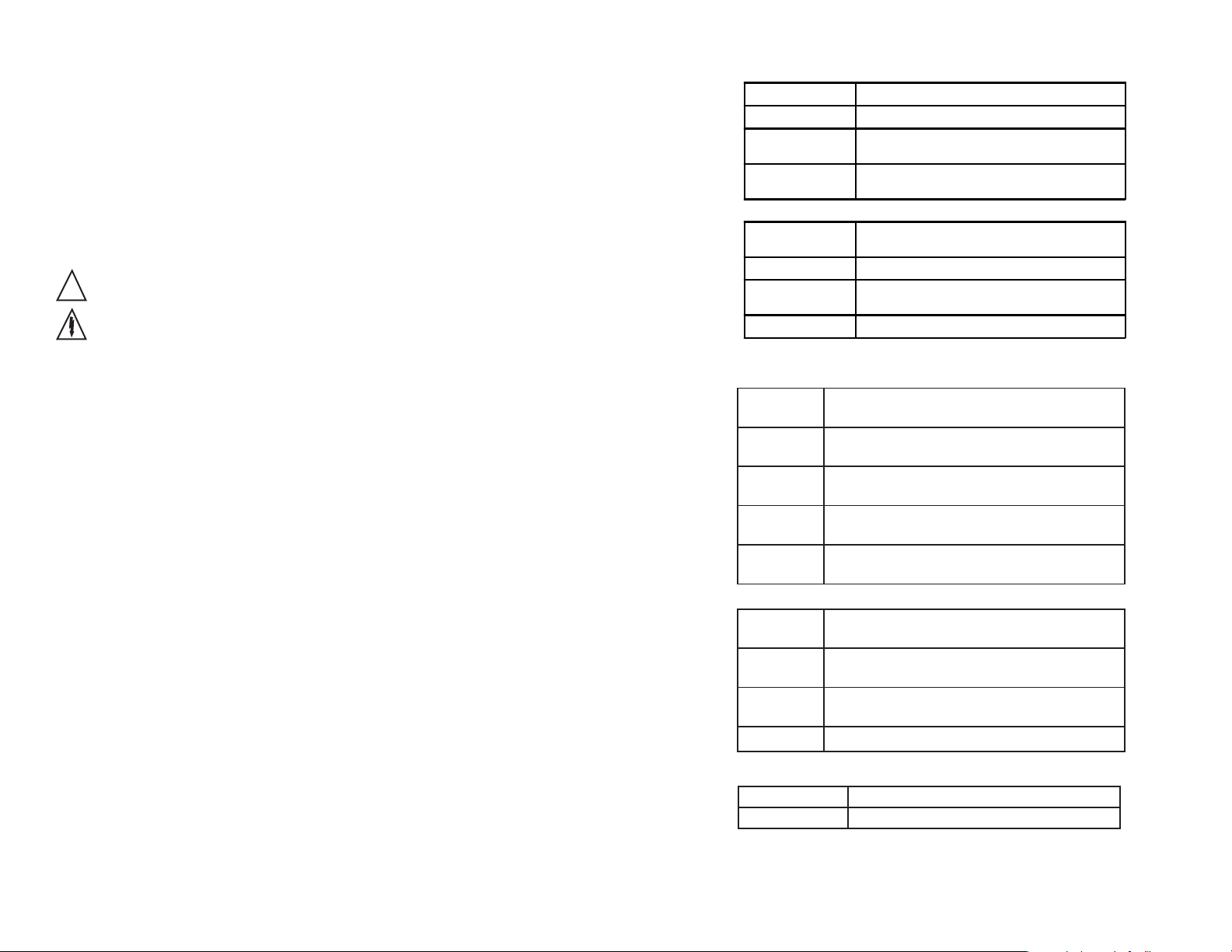
A.2 Electrical, Environmental and Mechanical
Specifications
Power Requirements
Power Consumption
Reset Input Signal
Storage Temperature
Operating Temperature
Relative Humidity
Bezel
Panel Cutout
Case Depth
Weight
AC Supply: 120 or 240 VAC, ±10%
3VA
Active Low: 0.2 VDC = active
-10 to 60°C
0 to 40°C
0 to 80% for temperatures less than 32°C,
decreasing linearly to 50% at 40°C. (Non-
condensing)
3.93" x 2.04" x 0.52" (99.8 x 51.8 x 13.3mm)
3.62" x 1.77" (92 x 45 mm) 1/8 DIN
3.24" (82mm)
9.0 oz. (255.1 g)
217
Page 4

1 Product Description
3.4 A/B Channel Inputs
The A channel input is a pulse source. This signal must be limited to under 35
KHz. This corresponds to a minimum pulse width of 28.57 microseconds. The
signal does not need an even duty cycle (On vs. Off time) as long as a minimum
(high or low) of 1 microsecond is maintained (See figure 15).
Tp (Minimum)
1.1 General Description
The S664 frequency counter fits a 1/8 DIN standard cutout and is perfect for
tight spaces, extending only 3.24” (82mm) behind the panel.
The unit is UL listed. The unit is for indoor use at altitudes up to 2000m, temperatures between 0° and 40°C, and installation category III, pollution degree 2.
The counter is powered from 120 or 240 VAC.
One of four frequency ranges may be selected to measure from 1Hz to 35KHz.
The counter accepts pulses from different types of sensors, including Quadrature, CMOS or TTL circuits and PNP or NPN devices.
An optional 12 VDC (100mA) excitation output module can provide power for
external sensors.
1 us
1 us
Figure 15. Input Pulse Definition
The B Channel acts as a direction control. If the B input is in the active state,
frequency will be displayed as a negative number. When using the quadrature
input card (in quadrature mode), A and B encoder signals are translated to Pulse
and Direction signals internally.
3 16
Page 5

3.2 Display Error Messages
1.2 Part Number Identification
Display Description
9999 or
-999
(Flashing)
E3
(Outputs
deactivate, count
stops)
Display Over Range: The displayed count is too
large for the counter to display. Since the internal
count buffer is much larger tha n the display, the
counter will maintain a ccurate frequency well
beyond the display value.
Watchdog Fault: The counter did not experience
an orderly power-down. This ca n h a ppen by
exceeding the maximum allowable count speed for
a sustained period of time.
Action
Required
Reset
Counter
Reset
Counter
3.3 Rate (Frequency) Scaling and Display
The S664 can measure frequencies ranging from 1.00 Hz to 35 KHz. The frequency scale is selected according to Table 4. The frequency range is selected
by using a wire or switch across the RESET and COMMON terminals on the
rear of the counter. The range prompt (scl 1) will toggle each time the contact is
made.
Typ ical
Update
Range
Period
1.0 sec 3.0 sec 1.00 Hz 99.99 Hz
scl1
1.0 sec 2.0 sec 1.6 Hz 999.9 Hz
scl2
0.5 sec 1.0 sec 4 Hz 9999 Hz
scl3
0.5 sec 1.0 sec 0.01 KHz 35.00 KHz
scl4
Max
Update
Period
Min.
Input
Frequency
Max.
Input
Frequency
Comments / Typical Application
1/100 Hz resolution / measure
1/10 Hz resolution / measure
1 Hz resolution / measure signals
0.01 KHz resolution / measure
Table 4. Frequency Scale Selection
signals less than 100 Hz.
signals less that 1 KHz
less than 10 KHz
signals in KHz
The following matrix indicates the configuration of your S664 counter.
Basic Unit
S664
Power Supply
120 VAC
240 VAC
1
2
Input
Standard
Quadrature
Output
0
1
2
None
Excitation
None
12VDC
0
1
Other
None
0
1.3 Option Module Summary
1
Input Exitation Power
Figure 1. Option Module Slots (Rear View)
The S664 is a modular product that uses field configuring slide-in modules. The
modules slide easily into the rear of the counter.
Figure 1 displays the functional assignments for each module position. Table 1
describes available option modules for the S664.
2
4
Supply
Frequency can also be displayed as a signed entity and will be negative according to the direction control. (See section 3.4.)
eludoM
tols
epyT N/P noitpircseD noitceSeeS
1tupnIeludoMtupnIdradnatS
1tupnI
2.moC/txE46054eludoMnoitaticx
ECDV21
4rewoPeludoMrewoPCAV022/021
Table 1. Option Module Summary
415
4.2
eludoM
tupnIlasrevinU/erutardauQ
5.2
6.2
3.2
Page 6

2 Hardware Setup
2.1 Panel Installation
The S664 1/8 DIN counter requires a standard 1/8 DIN panel cutout of 1.77”
(45mm) high by 3.62” (92mm) wide. To install the counter into a panel cutout,
remove the clips from the side of the counter. Slide the counter through your
panel cutout, then slide the mounting clips back on. Press evenly to ensure a
proper fit.
ISO+12V
ISOCOM
EXCITATION
Denotes module
position 2 at rear of
counter
+
12 VDC, 100 mA max
__
---
_
3.62"
92mm
3.24"
82mm
1.8"
45mm
1.74"
44mm
.52"
13.2 mm
3.93"
99.8 mm
Figure 2. Counter and Panel Cut-Out Dimensions
2.04"
51.8mm
Figure 13. Excitation Module
3 Display & Rear Panel Controls
3.1 Display
Numeric & Message Display
Units Window
Figure 14. Display Layout
• 6-digit 0.56” high red LED display.
• Units Window for supplied label or legend.
Figure 3. Panel Mounting Clips
5 14
• Upon power up, the S664 will identify its model and version.
Page 7

2.6 Excitation Module
!
DENOTES MODULE POSTION 1
AT REAR OF COUNTER
CHANNEL A-WHITE
CHANNEL B-GREEN
MODEL S.E.
QUADRATURE
ENCODER
+
POSITIVE (RED)
+
COMMON
(BLACK)
Figure 11. Wiring Encoder w/ Excitation Supply
12 VDC Excitation Module
The Excitation Module can supply 12 VDC at up to 100 mA for external sensors
or encoders. This excitation is isolated from the counter internal logic supply.
When using sensors or encoders that do not have a signal return or imply a signal return that is in common with the supply voltage, a common attachment that
ties the excitation supply to the logic input common may be required. Examples
of this appear in figures 8, 8a, 11 and 12.
A INPUT
COMMON
USER
INPUT
B INPUT
COMMON
INPUT
QUADRATURE
INPUT CARD
2.2 Removing / Installing Option Modules
Shut power off before removing or installing any option modules
1. Remove module from case by inserting a screwdriver into tab slot
opening at top of input module. Apply pressure to release module from
case. Repeat procedure for tab located on underside of module and
then slide module away from the case.
2. Refer to appropriate section to configure switch or jumpers for proper
operation. Table 1 can be used to identify modules and their associated
detail paragraph.
3. Install module by carefully aligning module edges with slots in case
and pressing forward until tabs (on top and bottom) engage.
Figure 12. Wiring Encoder with External Supply
Figure 4. Removing Option Module
613
Page 8

2.3 120/240 VAC Power Module
!
!
Table 3. Quadrature Module DIP Switch and Jumper Settings
Remove power before wiring option modules.
The AC power module allows the S664 to be operated
from standard 50/60 Hz line power. The power module will be configured as 120 VAC or 240 VAC per
markings on the back panel. Ensure the input rating
of the supply matches your line voltage. The power
supply module has provisions for a hard-wire Range
Select. This control can be a switch, relay contact or
solid state device. Actuation is immediate upon sn active Low for at least 2.5ms to this terminal. The reset
circuit is independent of the power circuit.
VAC
VAC
RESET
COMMON
POWER
!
Denotes module
position 4 at rear
of counter
Power Supply
120 VAC or 240
VAC power
connection
Mode Select
Active low steps
through range
selections
Figure 5. AC Power Module
NOTE: A fusible link is not provided on this module. A ½ Amp Time Delay
fuse, Bussman MDL ½, or similar, is required.
Never connect AC mains (hot or neutral)
2.4 Standard Input Module
Denotes module
position 1 at rear
A INPUT
COMMON
USER
INPUT
B INPUT
COMMON
INPUT
of counter
Primary Input
Connect the input
signal to A input
and common
Program Step
Used only in special
programming mode
Secondary Input
Direction Control or
count pulse input
Figure 6. Standard Input Module
JP1/2: Count Mode Selector
Jumpered 1-2 = Quadrature mode
Jumpered 2-3 = Standard counter mode
SW1: 10 Position DIP Switch
* = Factory Default setting
1 B Channel Bias: OFF = Hi* VLT = 5.0V VUT = 7.0V (+/- 10%)
ON = Low VLT = 1.6V VUT = 3.6V (+/- 10%)
2 B Channel Frequency: OFF = Hi* (low pass filter disabled)
ON = Low (low pass filter enabled)
3 B Channel Sensor: OFF = Sinking* (internal pull-up enabled)
ON = Source (internal pull-down enabled)
4 A Channel Bias: OFF = Hi* VLT = 5.0 V VUT = 7.0V (+/- 10%)
ON = Low VLT = 1.6 V VUT = 3.6V (+/- 10%)
5 A Channel Frequency: OFF = Hi* (low pass filter disabled)
ON = Lo (low pass filter enabled)
6 A Channel Sensor Type: OFF = Sinking* (internal pull-up enabled)
ON = Source (internal pull-down enabled)
7 B Channel Count Edge: OFF = Rising (standard count mode only)
ON = Falling*
8 A Channel Count Edge: OFF = Rising (standard count mode only)
ON = Falling*
9 User Input Polarity: OFF = High/open circuit = Inhibit Count
ON* = Low/closed circuit = Inhibit Count
10 Quadrature Mode: OFF = X4 (quadrature mode only)
ON = X1*
7 12
Page 9

The Quadrature mode supports a wide range of encoders including the Simpson
SE series.
While in Standard mode, this module works similarly to the Standard Input
module, with the added capability to selectively invert the A, B, and User input
signals.
NOTE: If B channel is not going to be used, use the default switch settings
for SW1 positions 1 through 3.
1
DIP Sitc
Son for TT ac tory Settings
CANNE
1 2 3 4 5 6
UNCTION
B Bias Offi On o
B re Offi On o
B Off Sin On S ource
A Bias Offi On o
A re Offi On o
A Off Sin On S ource
Default settings are provided in Table 3. In both modes, the state of the User
input signal can be selected as active high or active low. DIP switch SW1
configures the counter to match the specifications of the accompanying sensor.
When shipped from the factory, the counter is set for X1 quadrature, as shown in
Figure 10 and Table 3:
Denotes module
position 1 at rear
of counter
A INPUT
COMMON
Figure 9. Quadrature / Universal
Input Module
USER
INPUT
B INPUT
COMMON
INPUT
Primary Input
Quadrature A
Program Step
Used only in special
program mode
Secondary Input
or
Quadrature B
or
Note Refer to specifications
for DIP sitc funct ion
electrical caracteristics
Dipswitch Legend
=ON
= OFF
Figure 7. Standard Input Module Default Settings
DIP switch SW1, figure 7, is used to set up the counter to conform to the electrical characteristics of the sensor or signal being detected. Switch positions 1-3
configure channel B, while switches 4-6 configure channel A. These switches
select bias (threshold voltages), low pass filter (enable/disable) and sensor type
(Sink or Source). Refer to the documentation that accompanied the sensor for
related information. The sensor can most likely be matched to one of the typical
switch settings shown in figure 8 and figure 8a.
Note: The input boards are designed so that selecting sourcing or sinking is
based on the type of sensor that is being used. If a PNP (sinking) sensor is
being used, set the input board for sinking also (switches 3 and 6 = OFF).
If channel B is not used, default settings for switch positions 1 through 3 should
be selected. Default settings are provided in Table 2.
The Input module also provides for a User input signal. On the S664, this input
serves as a secondary channel (Rate) hard-wired reset. This may be used, for
example, to reset latched alarm outputs that have been assigned to rate.
Figure 10. Quadrature Input Module Default Settings
811
Page 10

The S664 can accept inputs from many different sensors. The A and B chan-
+
nels may be configured independently as shown in Table 2. Figures 8 and 8a
have examples of some typical sensors and the wiring connections that would be
used.
Table 2. Standard Input Module DIP Switch Settings
* = Factory Default setting
1 B Channel Bias: OFF = Hi* VLT = 5.0 V VUT = 7.0V (+/- 10%)
ON = Low VLT = 1.6 V VUT = 3.6V (+/- 10%)
HIGH BIAS
HIGH FREQUENCY
SINKING
ON
1 2 3 4 5 6
LOW BIAS
LOW FREQUENCY
SOURCING
A INPUT
COMMON
USER
INPUT
B INPUT
ISO+12V
ISOCOM
COMMON
EXCITATION
INPUT
ON
1 2 3 4 5 6
HIGH BIAS
HIGH FREQUENCY
SINKING
+
__
---
_
LOW BIAS
LOW FREQUENCY
SOURCING
A INPUT
COMMON
USER
INPUT
B INPUT
ISO+12V
ISOCOM
COMMON
EXCITATION
INPUT
+
__
---
_
2 B Channel Frequency: OFF = Hi* (low pass filter disabled)
ON = Lo (low pass filter enabled)
3 B Channel Sensor: OFF = Sinking* (internal pull-up enabled)
ON = Source (internal pull-down enabled)
4 A Channel Bias: OFF = Hi VLT = 5.0 V VUT = 7.0V (+/- 10%)
ON = Low* VLT = 1.6 V VUT = 3.6V (+/-10%)
5 A Channel Frequency: OFF = Hi* (low pass filter disabled)
ON = Lo (low pass filter enabled)
6 A Channel Sensor Type: OFF = Sinking* (internal pull-up enabled)
ON = Source (internal pull-down enabled)
OUTPUT
COMMON
NPN SENSOR
+
Figure 8. Sensor Connection Examples
ON
1 2 3 4 5 6
HIGH BIAS
HIGH FREQUENCY
SINKING
DRY CONTACT
LOW BIAS
LOW FREQUENCY
SOURCING
A INPUT
COMMON
USER INPUT
B INPUT
COMMON
INPUT
Figure 8a. Sensor Input example
PNP SENSOR
2.5 Quadrature Input Module
The Quadrature / Universal Input Module has two operational modes: Quadrature mode and Standard mode. Quadrature mode is selected by positioning JP1
and JP2 on pins 1 and 2. Standard mode is selected by placing JP1 and JP2 on
pins 2 and 3 (see Figure 10 for details).
109
 Loading...