

Page 1
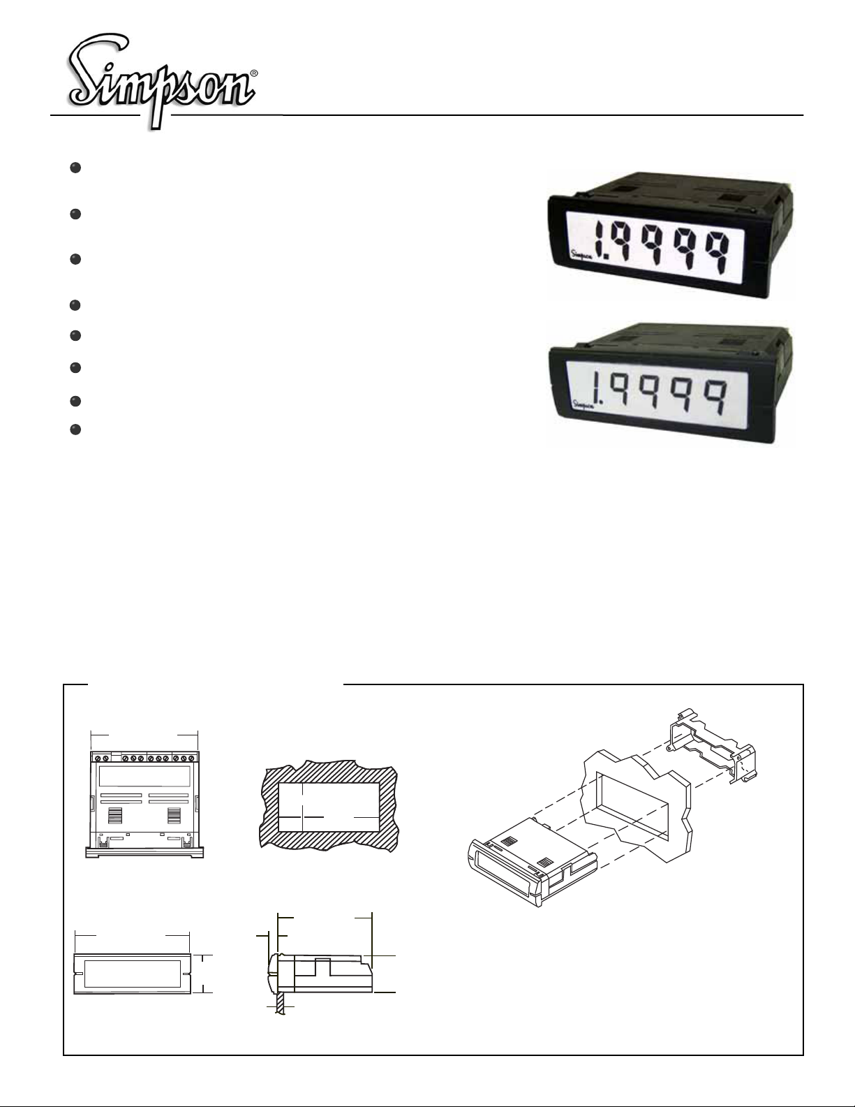
Mini-Max M245 Series Digital Panel Meter
Minimum Depth Indicator - Less Than 2.5” (60mm) of
Space Required Behind the Panel
Stackable Mounting Bracket Included for
Easy Installation
LCD: 4-1/2 Digit, 0.5” (12.7mm) High LCD Display with
Optional Negative Image, Bright Red Backlighting
LED: 4-1/2 Digit, 0.4” (10.2mm) High Display
Limited Range Display Scaling
Standard Screw Terminals for Easy Installation
Six Current Ranges: 200µA, 2mA, 20mA, 200mA, 2A, 5A
85-250VAC or optional 9-32VDC Power Supply
DC Current
LCD
LED
Simpson’s Mini-Max Voltage Indicators provide high quality,
accuracy and reliability in a compact, 60mm deep case.
LCD (Liquid Crystal Display) Units oer a 4-1/2 digit, 0.5”
(12.7mm) LCD display with an optional bright red, negative
image, backlight.
LED (Light Emitting Diode) Units oer a 4 1/2 digit, 0.4”
(10.2mm) Display.
Installation and Panel Cutout
2.68” (68mm)
0.88" (22.2mm)
2.68"
(68mm)
All units feature user-selectable decimal point, auto zero and
limited scaling capabilities.
A unique mounting bracket is provided to allow for vertical
or horizontal stacking of multiple indicators. All Mini-Max
units feature a 3/64 DIN, high-impact plastic case. The
LCD units have a clear viewing window, and the LED units
have a red viewing window.
2.84" (72mm)
0.95"
(24mm)
0.16"
(4mm)
2.36" (60mm)
0.13" (3.18mm) Max
Panel Thickness
0.874"
(22.2mm)
Mounting Requirements
Insert the Mini-Max through the panel, and then slide the mounting bracket
onto the Mini-Max. The mounting bracket allows Mini-Max units to be
stacked side-to-side or top-to-bottom and maintain the DIN standard
panel arrangements in 24mm by 72mm multiples. Panel cutout instructions for stacking multiple units are provided under “Stacking Features.”
Page 2
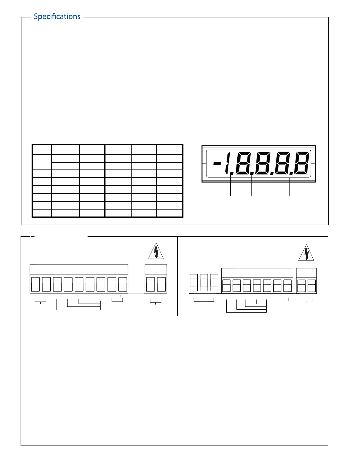
DISPLAY
Type: 7-segment LCD or LED
Height:LCD 0.5” (12.7mm)
LED 0.4” (10.2mm)
Decimal point:4-position selectable
Overrange indication:
LCD Most signicant digit = “1”
LED Blinking display
LCD Backlighting: Optional negative image, red
Polarity: Auto with “-” indication, “+” implied
POWER REQUIREMENTS
AC Volt: 85-250VAC @40-440Hz
DC Volt: 9-32VDC
Power Consumption: (Non Fused)
85-250VAC: LCD 4.0VA (2.4W) max
9-32VDC: LCD 3W max
Isolation: 250Vrms
DCA
LED backlighting
LED 3.6VA (2.16W) max
LED 2W max
LCD
NOISE REJECTION
CMRR: 86dB typical
ACCURACY @ 25°C
±(0.04% of reading ± 1 count)
2A: ±(0.25% of reading ± 1 count
5A: ±(0.5% of reading ± 1 count)
ENVIRONMENTAL
Operating Temperature:0 to 55°C
Storage Temperature:-10 to 60°C
Relative Humidity: 0 to 85% non condensing
@ 40°C
Temperature Coecient:
(0.2% of input ± 0.5 digits)/°C
Warmup time: Less than 20 minutes
ANALOG TO DIGITAL CONVERSION
Technique:Integrating dual slope
Rate: 3 samples/second-typical
LCD
LED
Range Resolution Voltage Max Input Voltage Max Input
M245
Drop Unfused Drop Unfused
200uA 10nA 200mVdc 10mA 200mVdc 6mA
2mA
100nA 200mVdc 40mA 200mVdc 20mA
20mA
1uA 200mVdc 100mA 200mVdc 60mA
200mA 10uA 200mVdc 400mA 200mVdc 300mA
2A 100uA 200mVdc
5A 1mA 50mVdc
3A 200mVdc 2.6A
6A 100mVdc
LED
6A
MECHANICAL
Bezel: 0.95” x 2.84” (24mm x 72mm)
Depth:2.36” (60mm)
Panel cutout: 0.88” x 2.68”
Weight: LCD 3.5oz (99.2g)
Case Material:
94-0,UL-rated, glass-lled thermoplastic
INPUTS: DC Current
(22.2mm x 68mm)
LED 2.6oz (74g)
DP4 DP3 DP2 DP1
Connections
LCD VERSIONS
POWER
IN HI+
IN LO-
INPUT SIGNAL
DP3
DP1
DP2
DP4/
HOLDDPCOMMON
WARNING: These instruments are designed for maximum safety to the operator when mounted in a panel according to
instructions. They are not to be used unmounted or for exploratory measurements in unknown circuits.
POS
EXCITATION
OUT
NEG
-DC
AC LINE
+DC
Input Signal: Connect the DC sig nal to be monitored to the IN HI+ and IN LO- input terminals.
Input Power: For AC power, connect the AC POWER LINE to the AC LINE inputs. For optional DC power, connect the DC Supply to
the DC inputs. Observe polarity.
Decimal Point: To select a decimal point, connect the appropriate DP input pin (DP1 - DP4) to the DP COMMON output. Unused DP inputs
may remain unconnected (open).
Connect the DP COMMON output to the HOLD input. If this feature is not required, the HOLD pin may remain unconnected.LCD Hold Option:
Hold is optional on LCD versions only, replaces DP4 and is available from our modication center.
IN HI+
NOT
USED
INPUT SIGNAL
IN LO-
DP3
LED VERSIONS
DP2
DP1
DP4
DP
COMMON
POS
EXCITATION
NEG
OUT
POWER
-DC
AC LINE
+DC
LCD Backlight
Option:
Negative image, bright red backlighting is available for the LCD versions only. This illumination allows the unit to be read in low
light areas. Backlighting power is supplied by the Mini-Max, so no additional external power is required.
Excitation Option: Excitation is available at the EXCITATION OUT Positive (POS) and Negative (NEG) terminals for powering external transmitters
or transducers. This source is isolated from the measurement input as well as the input power circuits. The voltages available
are 12Vdc or 24Vdc with a maximum load current of 25mA. This feature eliminates the need to mount an external DC power
source for transducers or sensors used in your application.
Page 3

LCD Display Scaling
TOP HALF
OF CASE
FRONT
OF METER
LOCKING
TAB
LCD VERSIONS
Scale Adjustment:
The "Coarse" adjustment R12 will allow a
limited range of adjustment values. The
"Fine" adjustment R9 allows for an adjustment range of approximately 1% of the
"Coarse" adjustment. Apply the full scale
input to the meter. Adjust R12 to be within
1% of the desired result. Then use R9 to
R12
R9
Using a screwdriver or thumbnail,
spread the tabs on each side of the case
to unlock the top half. Lift the rear of the
top half and slide it away from the front of
the meter.
Scale Adjustment:
Mini-Max indicators have limited range
scaling. There are no optional connections
required for these to function. The meter
can be scaled down to 1/2 the value of the
input, or scaled up to 1 times the value of
the input, or a maximum reading of 1.9999,
whichever is lower.
LED VERSIONS
Scale Adustment:
The "Coarse" adjustment RV1 will allow a
limited range of adjustment values. The
"Fine" adjustment RV2 allows for an adjustment range of approximately 1% of the
"Coarse" adjustment. Apply the full scale
input to the meter. Adjust RV1 to be within
1% of the desired result. Then use RV2 to
SCALE ADJ.
FINE
SCALE ADJ.
COARSE
Note: Any physical damage to the meter
during adjustment will void the warranty.
SCALE ADJ.
FINE
Note: Any physical damage to the meter
during adjustment will void the warranty.
SCALE ADJ.
COARSE
Stacking Features
The mounting brackets, included with every Mini-Max, can be connected
together. Multiple units can be mounted in a single opening, allowing
perfect alignment.
To punch one hole for multiple units, be sure to adjust the standard panel
in the hole.
remaining units.
Vertical
Standard cutout
0.88" (22.2mm)
2.68" (68mm)
0.071" (1.8mm)
Add to standard
when stacking
Horizontal
Standard cutout
0.88" (22.2 mm)
2.68" (68mm)
Vertical
Horizontal
0.16" (4.0 mm)
Page 4

Application Example
A company needs to monitor the power
supply voltage and load current of a 12V 4AMP
DC motor.
Voltage: A Mini-Max DC Volt Meter is installed
in parallel with the 12VDC power supply. The
IN HI + terminal is connected to the positive lead
of the power supply. The IN LO - is connected
to the negative lead of the power supply.
Current: A second Mini-Max 5ADC Ammeter is
connected in series with the DC MOTOR. The
IN HI + terminal is connected to the positive lead
of the power supply. The IN LO - terminal is connected to the positive lead of the DC motor. The
negative lead of the DC motor is connected to the
negative terminal of the 12VDC supply. The MiniMax units will indicate the DC motors supply
voltage and load current.
IN HI+
INPUT SIGNAL
IN LO-
5A DC UNIT
DP
DP4/
DP1
DP3
DP2
COMMON
HOLD
4A
DC MOTOR
POS NEG
EXCITATION
OUT
+DC
-DC
AC LINE
12VDC
POWER SUPPLY
20VDC UNIT
IN LO-
IN HI+
DP3
DP2
INPUT SIGNAL
DP1
DP4/
HOLD
Ordering Information Safety Symbols
DP
COMMON
POS
EXCITATION
OUT
NEG
-DC
AC LINE
+DC
The Mini Max Voltage Indicator can be congured by making an entry for each box
Basic Unit Display DPM Power Supply Range Excitation Output**
4-1/2 Digit Indicator
M245
0
Non Backlight (LCD)
1
Negative Image Red (LCD)
2
Red LED
2
85-250 VAC
9-32VDC
21
200µA
22
2mA
23
20mA
24
200mA
25
2A
26
5A
**25 mAdc max output
None
0
12VDC
1
24VDC
2
0
NOTE: The LCD Display hold feature is congured at the factory only and must be specied at
the time of order.
Accessories
Portable
Switchboard
External shunts enable digital meters to indicate
higher currents. A shunt is installed in series between
the source and load. The shunt produces a DCmV
drop which is measured by the Mini-Max meter. The
Mini-Max can be scaled to display the actual current
between the load and the source. Simpson manufactures portable and switchboard shunts. Each
portable shunt includes 5’ leads.
Example: 25Amp DC is to be measured. A Mini-Max
M235 3 1/2 digit 200mVdc meter and 25Amp shunt,
Cat. No. 06707 are selected for this application. 25Adc
owing through the shunt generates 50mV which is
applied to the IN HI+ and IN LO- inputs of the meter.
The 50mV would normally display as 50.00 on the
meter. By using the scale adjustments, the meters
scale factor may be adjusted to 1/2. The meter will
now display 25.00 thus providing a 25Amp indication.
The WARNING sign denotes
a haza rd. It calls attention to
a procedure, practice, or the
like, which, if not correctly
performed or adhered to,
co uld resu lt in persona l
injury.
The CAUTION sign denotes
a haza rd. It calls attention to
an operating procedure,
practice, or the like, which, if
not correctly adhered to,
could result in damage to or
destruction of part or all of
the instrument.
Ordering Information
Portable Shunts 50mV
Amps
1
5
10
15
25
30
50
75
100
150
200
Switchboard Shunts 50mV
Amps
100
150
200
250
300
400
500
Cat. Number
06700
06703
06704
06705
06707
06708
06709
06711
06713
06714
06715
Cat. Number
06500
06503
06504
06505
06506
06507
06508
SIMPSON ELECTRIC COMPANY
Printed in U.S.A.
11/11 ,12 noitidE ,170611-60 .oN traP
 Loading...