

Page 1
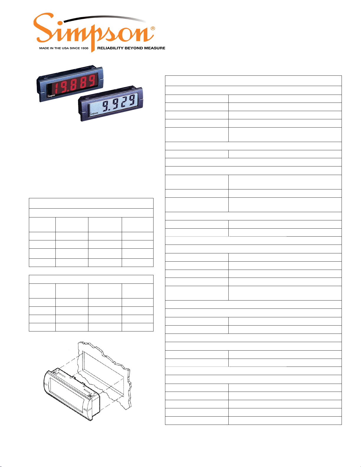
• 3/64 DIN Indicator
1
Rev. 07-01-13
Mini M135 & M145
Digital Panel Meters
Specications
DISPLAY
Type 7- segment LCD
Height 0.5” (12.7mm)
Decimal Point Position User-Selectable
Overrange Indication Most signicant = “1” other digits blank
Backlighting Optional negative image, red backlighting at
5, 10. 12, 24 or 48 DCV
• Minimum depth - requires less than 0.7”
(17mm) behind the panel
• Snaps right into panel - no mounting
hardware required
Input Specications
DC Voltage
M135
Range
200mV 100μV >100MΩ 50V
Resolution
2V 1mV 10MΩ 250V
20V 10mV 10MΩ 250V
200V 100mV 10MΩ 250V
DC Current
M135
Range
200μA 100nA 200mV 10mA
20mA 10μA 200mV 100mA
200mA 100μA 200mV 400mA
Resolution
2mA 1μA 200mV 40mA
Input
Impedance
Voltage
Drop
Max Input
(Unfused)
Max Input
(Unfused)
Polarity Auto with “-” indication, “+” indication implied
POWER REQUIREMENTS
DC Power ±5V, +5V and +9V
Low Power Indication included with 9V units
Power supply current 2mA max
Backlight supply current 50mA typical
For 24 and 48 DCV, 10mA typical
ACCURACY @ 25°C 3 1/2 digit: ± (0.1% of reading + 1 count)
4 1/2 digit: ± (0.04% of reading + 1 count)
ENVIRONMENTAL
Operating Temperature 0 to 55ºC
Storage Temperature -10 to 60°C
Relative Humidity 0 to 85° non-condensing @ 40°C
Warmup time Less than 20 minutes
Temperature Coefcient (All inputs)
± (0.02% of input ± 0.2 digit) / °C
NOISE REJECTION
NMRR 60dB, 50/60 Hz
CMRR (with 1KΩ unbalanced @ 60Hz) 90dB min
A TO D CONVERSION
Technique Integrating
Rate 3 samples/second-typical
MECHANICAL
Bezel 0.94” x 2.83”
Depth 0.43”
Panel cutout 0.89” x 2.71” (22.6 mm x 68.8 mm)
Weight 1.0 oz. (28.3 g)
Case Material
94-VO, UL-rated ABS
Page 2

Mini M135 & M145
2
Rev. 07-01-13
Clear Order Form
Digital Panel Meters
Ordering Information -
Mini indicators can be congured by making an entry in each section below.
Example: M135-0-2-11-0
_____ _____ _____ _____
I I I I I
Basic Unit Display DPM
Power
Supply
Select From Each One Below Select From Each One Below
Basic Unit Function / Range Backlight Power
M135 3 1/2 Digit LCD 11 200 DCmV 0 None
M145 4 1/2 Digit LCD 12 2 DCV 1 5 DCV
13 20 DCV 2 10 DCV
Display 14 200 DCV 3 12 DCV
0 Non Backlit 4 24 DCV
1
Negative Read Backlight 21 200 DCµA 5 48 DCV
22 2 DCmA
DPM Power Supply 23 20 DCmA
0 + 5 DCV 24 200 DCmA
1 ± 5 DCV
2 + 9 DCV
Function/
Range
Backlight
Power
Mounting Requirements -
The Mini indicators require a panel cutout of 2.71” (68.8mm) wide by 0.89” (22.6mm) high,
and a panel area of 0.94” (24mm) high by 2.83” (72mm) wide.
The depth behind the panel, including terminals, is 0.7” (17.8mm).
The front bezel protrudes 0.16” (4mm) from the front of the mounting surface.
The unit will snap-mount into panels from 0.050” to 0.125” thick.
A 12-pin connector with 6” wire leads is included with each unit for quick installation.
Installation and Panel Cutout -
2.68"
.89"
2.71"
2.83"
.94"
.16"
.125"
.43"
.86"
.29"
 Loading...