

Page 1
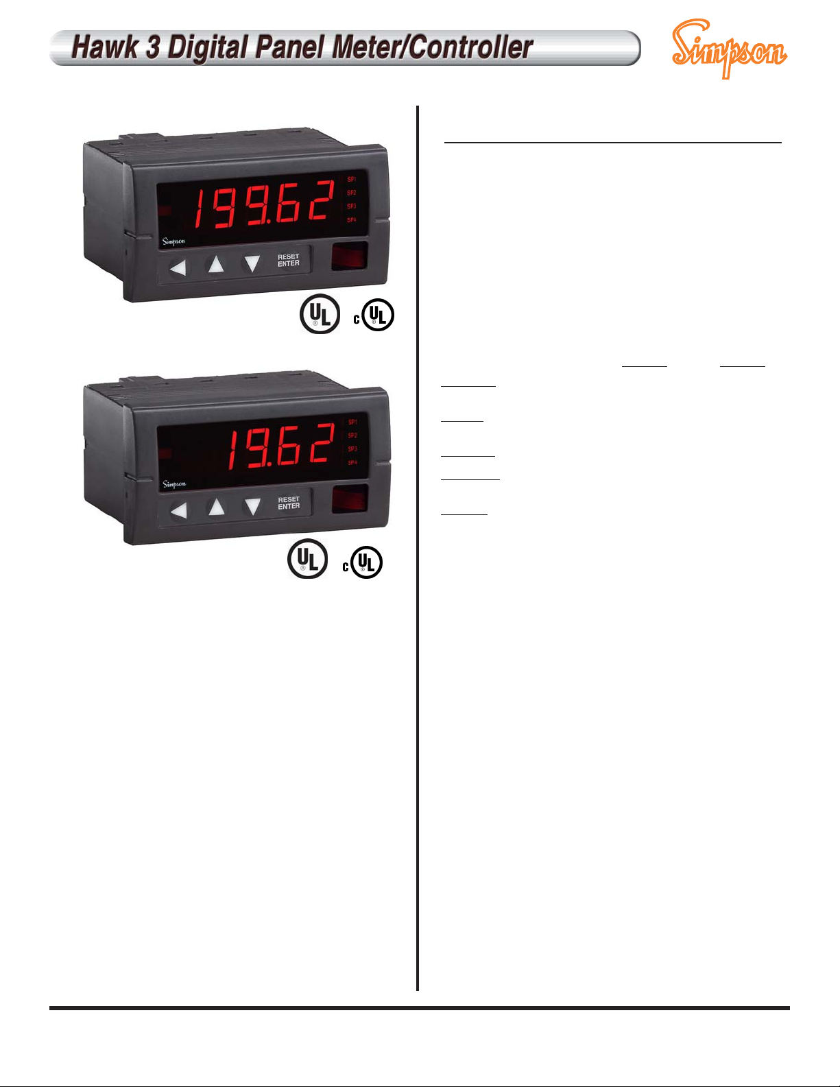
• All parameters set from easy to understand
front panel access
• One, two or four 5-amp relays optional
• Five user-selectable brightness levels
•1/8 DIN, shallow depth case, 3.24”
• RS485 digital communications optional (H345)
• 12 or 24 DCV power supply output optional
• 4-20mA or 0-10 DCV analog transmission
optional
• NEMA 4X rated front panel
• DIN Rail adapter available (page C1)
Specifications
7-segment, red LED
4 or 5
5 user-selectable levels
0.56" (14.2mm)
4 or 5 position, user programmable
Display flashes “EEEEE” indicating
Maximum Value Exceeded
Display flashes “-EEEE” indicating
Minimum Value Exceeded
4 LED indicators for up to four independent setpoints
120, 85-250 VAC @ 10VA
9-36 DCV @ 10VA
0 to 50°C
-10 to +60°C
<80%
25°C
100 ppm/°C
10 minutes
60 dB @ 50-60 Hz
70 dB @ 50-60 Hz
Successive approximation with oversampling
10 conversions per second
User programmable
1-420 updates/min (240 default)
3.9" x 2.0" x 0.52” (99.8mm x 51.9mm x 13.2 mm)
3.24" (82.3 mm)
3.62" x 1.77" (92 mm x 45mm)
10 oz (283.5g)
NEMA 4X Rated front panel
DISPLAY
Type
Quantity
Brightness
Height
Decimal point
Overrange indication
Underrange indication
Alarm Indicators
POWER REQUIREMENTS
AC
DC
ACCURACY @ 25°C as % of rdg
DC Current
High (5A, 2A)
All Others
DC Volts
High (600 V)
All others
Resistance
All ranges
*AC Current
High (2A, 5A)
All others
*AC Volts
High (600V)
All others
ENVIRONMENTAL
Operating TTemperature
Storage TTemperature
Relative HHumidity
Ambient TTemperature
Temperature DDrift
Warmup
ttime
Noise RRejection
NMRR
CMRR
A TO D CONVERSION
Technique
Sample RRate
Display RRate
MECHANICAL
Bezel
Depth
Panel ccutout
Weight
Cover
4-11/2 ddigit
3-11/2 ddigit
0.2% ± 1 count
0.05% ± 1 count
0.1% ± 1 count
0.05% ± 1 count
0.1% ± 2 counts
0.2% ± 2 counts
0.1% ± 2 counts
0.1% ± 1 count
0.05% ± 1 count
0.3% ± 1 count
0.1% ± 1 count
0.2% ± 1 count
0.1% ± 1 count
0.1% ± 2 counts
0.3% ± 2 counts
0.2% ± 2 counts
0.2% ± 1 count
0.1% ± 1 count
* AC functions measured at 50 Hz, include ± 1 count for each additional
100 Hz above 50 Hz
more >>
For more information, visit www.simpsonelectric.com
Page 2

HHaawwkk 33 IInnddiiccaattoorrss ccaann bbee ccoonnffiigguurreedd bbyy mmaakkiinngg aann eennttrryy iinnttoo eeaacchh sseeccttiioonn.. EExxaammppllee:: HH333355-33-7711-00-44-11
Basic Unit Power Supply Function/Range Output Signal 5A Relay Excitation
Basic Unit
3-1/2 digit, Red LED
4-1/2 digit, Red LED
Power Supply
Function/Range
Continued on next column
Ordering Information
1
2
3
4
81
82
83
84
0
1
2
6
0
1
2
4
0
1
2
71
72
51
52
53
54
55
H335
H345
11
12
13
14
15
21
22
23
24
25
26
61
62
63
64
65
66
41
42
43
44
45
46
31
32
33
34
35
* Awaiting UL approval
Selection Description
Selection Description
Function/Range continued
120 ACV (3-1/2 only)
85-250 ACV (4-1/2 only)
9-36 DCV
85-250 ACV (3-1/2 only)
200 DCmv
2 DCV
20 DCV
200 DCV
600 DCV*
200 DCµA
2 DCmA
20 DCmA
200 DCmA
2 DCA
5 DCA
200 ACmV
2 ACV
20 ACV
200 ACV
600 ACV*
200 ACµA
2 ACmA
20 ACmA
200 ACmA
2 ACA
5 ACA
200 ACmV TRMS
2 ACV TRMS
20 ACV TRMS
200 ACV TRMS
600 ACV* TRMS
200 ACµA TRMS
2 ACmA TRMS
20 ACmA TRMS
200 ACmA TRMS
2 ACA TRMS
5 ACA TRMS
4-20 DCmA Process
0-10 DCV Process
200 Ohm
2K Ohm
20K Ohm
200K Ohm
None
4-20 DCmA
0-10 DCV
RS-485 (4-1/2 only)
None
One
Two
Four
None
12 DCV
24 DCV
Output
5A Relays
Excitation
For more information, visit www.simpsonelectric.com
Page 3

Installation and Panel Cutout - H335, H340, H345
Engineering Label Placement
To replace the engineering unit label, place the tip of a ballpoint pen
into the small hole at the base of the engineering label in the bezel.
Slide the label up until it pops out. Grasp and remove. Slide the
new label half the distance in, then use the ballpoint pen to slide it
into place.
Mounting Requirements
The Hawk 3 Advanced Digital Controller 1/8 DIN meters require a
panel cutout of 1.77” (45mm) high and 3.62” (92 mm wide). To
install the Hawk 3 meter into the panel cutout, remove the clips from
the side of the meter. Slide the meter through the panel cutout, then
slide the mounting clips back on the meter. Press evenly to ensure
a proper fit. Tighten screws.
Range Resolution Resolution Input Overload
4.5 3.5 Impedance
200mV 10µV .1 mV 1 M⍀ 10DCV
2 V .1mV 1 mV 1 M⍀ 100DCV
20 V 1mV 10 mV 2 M⍀ 100DCV
200 V 10 mV .1 V 2 M⍀ 300DCV
600 V .1 V 1V 2 M⍀ 1K DCV
DC Voltage
Range Resolution Resolution Input Overload
4.5 3.5 Impedance
200µA 10 n A .1 m A 1K ⍀ 11mA DC
2 mA .1µA 1 mA 100⍀ 35mA DC
20 mA 1µA 10 mA 10⍀ 1 1 1 mA DC
200 mA 1 0 µ V . 1 m A 1 ⍀ 353 mA DC
2 A .1 mA 1 mA .013⍀ 7A DC
5 A .1 mA 1 mA .013⍀ 7A DC
DC Current
Range Resolution Resolution Input Overload
4.5 3.5 Impedance
200mV 10µV .1 mV 200K⍀ 10DCV
2 V .1mV 1 mV 200K⍀ 100DCV
20 V 1mV 10 mV 2 M⍀ 300DCV
200 V 10 mV .1 V 2 M⍀ 300DCV
600 V .1 V 1V 2 M⍀ 1K DCV
AC Voltage
Range Resolution Resolution Input Overload
4.5 3.5 Impedance
200µA 1 0 n A .1 mA 1K ⍀ 11mA AC
2 mA .1µA 1 mA 100⍀ 35mA AC
20 mA 1µA 10 mA 10⍀ 111mA AC
200 mA 1 0 µ V . 1 m A 1 ⍀ 353mA AC
2 A .1 mA 1 mA .013⍀ 7A AC
5 A .1 mA 1 mA .013⍀ 7A AC
AC Current
Range Resolution Resolution Input Overload
4.5 3.5 Impedance
200m⍀ 10m⍀ .1⍀ 1.2K⍀ ⴞ 5DCV
2⍀ .1⍀ 1⍀ 12K⍀ ⴞ 5DCV
20⍀ 1⍀ 10⍀ 121⍀ ⴞ 5DCV
200⍀ 10⍀ .1⍀ 1.2M⍀ ⴞ 5DCV
Resistance
Inputs
For more information, visit www.simpsonelectric.com
3.59”
.52”
3.93”
2.04”
1.77”
3.62”
3.24”
1.75”
 Loading...