

Page 1
DISPLAY
Type: 7-segment, red LED
Height: 0.56” (14.2mm)
Decimal Point: 3-position software program-
mable from front panel
Overrange: Display reads “EE”
Underrange: Display reads “-EE”
Alarm Indicators: Two LED indicators for
alarm conditions on front panel
POWER REQUIREMENTS
AC Voltages: 24, 48, 120, 220VAC, ±10%
DC Voltages: 12-48VDC, ±15%
Power Consumption: 6VA
ACCURACY:
0.2% of reading ± 2 counts
APPROVALS:
UL recognized; CSA and; CE certified
ENVIRONMENTAL
Operating Temperature: 0°C to +50°C
Storage Temperature: -10°C to +60°C
Relative Humidity: <90% non-condensing
Ambient Temperature: 23°C
Temperature Coefficient (per °C):
±100PPM/ °C
±0.05dgt/ °C
Warmup Time: 10 minutes
NOISE REJECTION
NMRR: 50db, GR = 50
CMRR: 100db, GR = 1
ANALOG TO DIGITAL CONVERSION
Technique: Special dual slope
Rate: Approximately 2 display updates per
second, nominal
MECHANICAL
Depth: 3.24” (82mm)
Bezel: 3.8” x 1.9” x 0.32”
(96mm x 48mm x 8.1mm)
Panel Cutout: 3.6” x 1.8”
(92mm x 45mm) 1/8 DIN
Case Material: ABS/polycarbonate blend
Weight: Approximately 10.5oz (297.7g)
Specifications
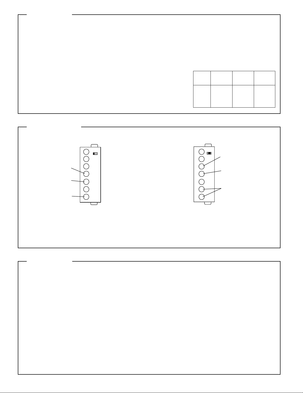
Wiring Diagram
Input Signal: Connect the signal to be monitored to the IN HI and the IN
LO terminals. Note that the IN HI signal has two terminals that can be
used, depending on the process being monitored. The upper IN HI terminal accepts 4-20 mA inputs. The lower IN HI terminal accepts 1-5VDC
and 0-10VDC inputs.
Supply Power: Connect the power to the supply power terminals.
Display Hold: Short the terminals marked HOLD to activate. The com-
parison of the input variable with the alarm set point remains active. To
reactivate this display, disconnect the short circuit.
Programming
INPUTS: DC Process
Input Power (-)
Input Power (+)
Display Hold
The Programming mode allows the user to define the instrument parameters:
- Password for access to programming
- Decimal point position
- Minimum and maximum values of the electrical range
- Display scaling
The normal measurement and control functions are not active during programming mode. The output relays are de-energized. Analog outputs
are low.
Termination of programming mode and return to the measurement and
control mode is automatic at the end of all the programming steps or
after three minutes with no key activation. Display will briefly show “End,“
then “Run.“
Access to programming
Press and hold the S key and then press ▲. The display should show
“PAS.” During this phase the instrument asks for the password, which is
a number from 0 to 199. The instrument is delivered with a password of
0. Use the ▲ and ▼ keys to change the displayed value. Press S to
enter the password and move to the next parameter.
If a number from 0 to 99 is used as the password, the operator cannot
change any of the parameters without knowing the password. This is
helpful in locking out the front panel from accidental programming. In situations where the operator needs the flexibility to change the set points
only, use a password from 100 to 199. This allows the operator to
access the set point programming mode, but jumps past the other programming functions. If the correct password is entered, the programming functions are accessed as normal.
IN LO
Signal Input
IN HI 4-20mA
Signal Input
IN HI 1-5V, 0-10V
Signal Input
Maximum
Input Display Voltage Overload
Range Resolution Drop (10 Sec.)
4-20mA 10A 0.2V 200mA
(Input
Impedance) (1 Min.)
1-5V 10mV 1M 690V
0-10V 10mV 1M 690V
 Loading...