

Page 1

GIMA
Modbus Communications
December 2008
Page 2
Safety & Programming
GIMA
1 Safety
The GIMA is intended for connection to dangerous voltages giving a risk of electric shock.
Refer to the safety/installation instructions in the GIMA Operating Manual before connecting
the communications.
WARNING
The meter contains no user serviceable parts. Installation and commissioning should only be
carried out by qualified personnel
2 Programming
Meters fitted with the Modbus option have two additional stages in the front panel programming
menu.
To enter programming mode:
Hold Amp and scroll together for 5 Seconds.
Press repeatedly until the required setup page is displayed.
RS485 Baud Rate
Modbus Meter ID
9
bAU
R
A
TE
6
C
Ad
U
b
d
d
0
E
r
0
Press p or qto select from the
list of valid baud rates. (4800-
19200)
Press
Press p or q to increment or
decrement the value within the
valid range (1-247).
Press to accept the set value.
to accept the set value.
For full information on entering and using programming mode refer to the latest “GIMA
Operators Manual "
1
Page 2 GIMA
Page 3

Connection GIMA
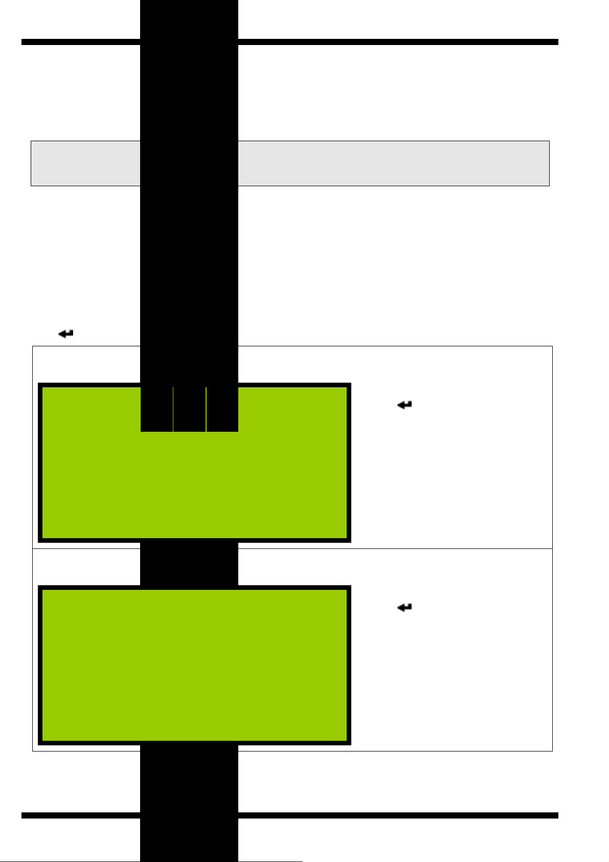
3 Connection
3.1 Cable Selection
A dedicated, screened twisted pair cable is required to provide basic RS485 connection. A
second twisted pair may be used for 0V connection if required. The cable should be chosen to
suit the data rate and maximum length to be installed. The EIA RS-485-A standard provides
curves that relate cable length to data rate for 24 AWG screened, twisted pair, telephone cable
with a shunt capacitance of 50pf/m. For baud rates up to 19,200 the standard suggests a
maximum length of 1200m for this type of cable. If other types of cable are to be used it is
recommended that the cable supplier is consulted as to the suitability for use with RS485 to
19,200 baud.
3.2 Signal 0V and Cable Shield
A signal 0V termination is provided on each meter. Although RS485 does not strictly require a
signal 0V, it is recommended this is connected as shown in the diagram below. This creates a
known reference for the isolated RS485 system thereby reducing potential common-mode errors
in the meter’s RS485 driver circuit.
A cable shield is used to attenuate noise picked up from external sources. This should be
continuous, and cover as much of the signal pairs as possible. It is recommended that the shield
should be connected to ground at the host (PC) only. The cable shield should not be used as the
0V connection.
3.3 Terminating Resistors
In order to minimise signal errors due to noise over long cable lengths, terminating resistors may
be fitted. These match the RS485 device impedance to that of the cable. Two 120Ω resistors,
one at the host port terminals and the other at the most remote meter terminals are recommended
for this purpose.
3.3.1 Connection To Meters
The bus should be taken to meters at each location for termination, using the meter terminals as a
loop in-out connection. The use of spurs should be avoided wherever possible.
Figure 3-1 Basic RS485 To Internal Modbus Option
Note 1 Depending on application these leads
may need to be reversed.
Page 3 GIMA
Page 4
Connection GIMA
4 Protocol
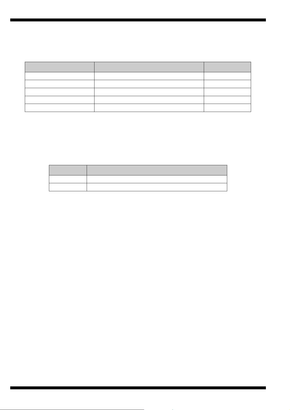
4.1 Modbus Commands
The GIMA meter supports the following standard Modbus commands:
Command Function Broadcast
03 Read Multiple Holding Registers No
04 Read Multiple Input Registers No
06 Preset a Single Register Yes
08 (SF=00) Sub Function 00 only (Loop Back) No
16 Preset Multiple Registers Yes
4.2 Exception Responses
If the meter receives a Modbus command, with no errors and a valid address, it will attempt to
handle the query and provide an appropriate response. If the meter cannot handle the query a
standard Modbus exception response is sent (except broadcast queries). An exception response
is characterised by its function byte which has 80H added to that sent in the query. The following
exceptions codes are supported:
Code Function
1 Preset data is out of range for parameter
2 Function cannot access requested register address
Page 4 GIMA
Page 5

Data Tables GIMA
5 Modbus Data Tables
5.1 Using The Tables
For convenience, meter data is organised in tables of like information with the same format. An
entire table may be read with a single Modbus command 3 (Holding Registers). For compatibility
with the Modbus standard each register contains a single data Word (16 bits). Data in the meter
is stored as:
Unsigned Integer (U-INT)
16-bit data in the range 0 to 65,535. This is used for parameters such as CT prim as this can
never be negative.
Signed Integer (S-INT)
16-bit data in the range –32,767 to +32,767. This is used for parameters such as instantaneous
kW, which may have a negative value indicating export power.
Long Integer (LONG)
32-bit data in the range 0 to 4,294,967,295. This is used for parameters such as kWh, which may
have large values. Each LONG requires two consecutive Modbus data words. Standard software
often handles long integer reads, however, a LONG may be calculated from the individual data
words as:
LONG = (65536 x High Word) + Low Word
Note:
individual GIMA (eg Harmonics on Meter Type 1) may return zero.
Table data values corresponding to measurements not available on an
5.2 Energy Registers
Data
Modbus
Data Access
Address
512 40513 eScale High Word
513 40514 eScale Low Word
514 40515 kWh High Word
515 40516 kWh Low Word
516 40517 kVAh High Word
517 40518 kVAh Low Word
518 40519 kvarh Inductive High Word
519 40520 kvarh Inductive Low Word
520 40521 kvarh Capacitive High Word
521 40522 kvarh Capacitive Low Word
522 40523 Import kvarh High Word
523 40524 Import kvarh Low Word
524 40525 Export kWh High Word
525 40526 Export kWh Low Word
526 40527 Export kvarh High Word
527 40528 Export kvarh Low Word
Register
Read Only
Read/Write
Read/Write
Read/Write
Read/Write
Read/Write
Read/Write
Read/Write
Page 5 GIMA
Page 6

Data Tables GIMA
Energy registers are stored as long integer representations of the number displayed on the meter
without decimal point or scaling. For example if the meter displays 123456.78kWh, the Holding
Registers 40515-40516 will contain the long integer 12345678. This number may be scaled in Wh
or kWh, using eScale as:
Wh = Holding Reg[40513] x 10
kWh = Holding Reg[40513] x 10
The eScale constant is set, along with the kWh register resolution and scaling, by the CT primary
and nominal voltage programmed settings. The display scaling and eScale therefore remain
constant once a meter is installed and commissioned. A read of eScale High Word always returns
zero.
Example:
If the meter displays 1234567.8 kWh then eScale would be 5 and the Holding Register 40513
would contain 12345678.
The host would calculate the scaled energy reading as:
12345678 x 10
or 12345678 x 10
(5-3)
= 12345678 x 100 = 1,234,567,800 Wh
(5-6)
= 12345678 x 0.1 = 1,234,567.8 kWh
(eScale-3)
(eScale-6)
The host programmer could take two approaches to interpreting the data from the meter:
ü Enter a fixed scaling factor (x100 for Wh or x0.1 for kWh in above example). This would be
set for each meter in the system based on its display after commissioning.
ü Use the transmitted eScale constant, as shown above, to automatically position the decimal
point in the interpreted result.
Page 6 GIMA
Page 7

Data Tables GIMA
5.3 Instantaneous Meter Values
Data
Modbus
Data Scaling
Address
2816 42817 System kW Kp
2817 42818 System kVA Kp
2818 42819 System kvar Kp
2819 42820 System PF 1000 = 1.000
2820 42821 Frequency 5000 = 50.00
2821 42822 Phase 1 Volts Kvp
2822 42823 Phase 1 Amps Ki
2823 42824 Phase 1 kW Kp
2824 42825 Phase 2 Volts Kvp
2825 42826 Phase 2 Amps Ki
2826 42827 Phase 2 kW Kp
2827 42828 Phase 3 Volts Kvp
2828 42829 Phase 3 Amps Ki
2829 42830 Phase 3 kW Kp
2830 42831 Phase 1 PF 1000 = 1.000
2831 42832 Phase 2 PF 1000 = 1.000
2832 42833 Phase 3 PF 1000 = 1.000
2833 42834 Ph1-Ph2 Volts Kvl
2834 42835 Ph2-Ph3 Volts Kvl
2835 42836 Ph3-Ph1 Volts Kvl
2836 42837 Neutral Current Ki
2837 42838 Amps Scale Ki 2838 42839 Phase Volts Scale Kvp 2839 42840 Line Volts Scale Kvl 2840 42841 Power Scale Kp -
Note: All values in this table are Signed Integers with read only access.
Register
Page 7
GIMA
Page 8

Data Tables GIMA
Instantaneous readings are provided as signed integer values with no decimal point or legend (e.g.
kW or MW). Scaling factors are provided to enable conversion of the raw data to real numbers in
basic unit form (amps, volts, watts, VA, or var). These scaling factors are constant values
calculated as a function of CT and PT Primary programming.
To convert raw data to real numbers:
R = I x 10
(K-3)
Where:
K = Relevant Scaling Factor
R = Real number result
Example:
If the meter is programmed with CT Primary=50Amps and PT Primary=415V:
LCD values would be scaled as: 50.00A, 240.0V, 415.7V
Scaling factors would be: I Scale=1, Kvp=2, Kvl=2, Kp=4.
Integer Values would be transmitted as: 5000, 2400, 4157 and 3600
Amps would be calculated as 5000 x 10
Phase Volts would be calculated as 2400 x 10
Line Volts would be calculated as 4157 x 10
3-Ph Power would be calculated as 3600 x 10
I = Integer number
(1-3)
and 36.00kW.
LL
= 5000/100 = 50.00A
(2-3)
= 2400/10 = 240.0V
(2-3)
= 4157/10 = 415.7V
(4-3)
= 3600x10 = 36000W
Page 8 GIMA
Page 9

Data Tables GIMA
5.4 Additional Instantaneous Values
Data
Modbus
Data Scaling
Address
3072 43073 Phase 1 kVA Kp
3073 43074 Phase 2 kVA Kp
3074 43075 Phase 3 kVA Kp
3075 43076 Phase 1 kvar Kp
3076 43077 Phase 2 kvar Kp
3077 43078 Phase 3 kvar Kp
Note: All values in this table are Signed Integers with read only access.
Register
5.5 Peak Hold Values
Data
Modbus
Data Scaling
Address
3328 43329 Peak Hold Ph1 Amps Ki
3329 43330 Peak Hold Ph2 Amps Ki
3330 43331 Peak Hold Ph3 Amps Ki
3331 43332 Peak Hold Ph1 Volts Kvp
3332 43333 Peak Hold Ph2 Volts Kvp
3333 43334 Peak Hold Ph3 Volts Kvp
3334 43335 Peak Hold kW Demand Kp – 1
3335 43336 KW Demand Period 1-60 Minutes
3336 43337 KW Demand Kp – 1
Note: All values in this table are Signed Integers with read/write access except 43336 and 43337,
which have read only access.
Register
5.6 Meter Setup
Data
Modbus
Data Scaling
Address
3584 43585 CT Primary 10 - 25,000 Amps
3585 43586 Nominal Volts 10 - 55,000 Volts
3586 43587 Pulse 1 Rate 1-1000 Counts/Pulse
3587 43588 Pulse 2 Rate (= Pulse 1 Rate) 1-1000 Counts/Pulse
3588 43589 Baud 96 = 9600baud etc
3589 43590 Modbus ID 0 – 247
3590 43591 Meter Model MultiCube = 100
3591 43592 Meter Type 1 - 6
3592 43593 Firmware Version Eg. 0x1A = 1.10
3593 43594 Current Demand Period 1 = 10Sec, 2=20Sec etc
3594 43595 Pulse ON Time 1 = 100ms, 2=200ms etc
3595 43596 Security Code 0 - 9999
Note: All values in this table are unsigned Integers with read/write access except 43591-43593
which are read only.
Register
Page 9 GIMA
Page 10

Data Tables GIMA
5.7 Peak Hold Current Demand
Data
Modbus
Data Scaling
Address
3840 43841 Peak Ph1 Amps Demand Ki
3841 43842 Peak Ph2 Amps Demand Ki
3842 43843 Peak Ph3 Amps Demand Ki
3843 43844 Peak Ph1 Volts Demand Kv
3844 43845 Peak Ph2 Volts Demand Kv
3845 43846 Peak Ph3 Volts Demand Kv
Note: All values in this table are Unsigned Integers with read/write access.
Register
5.8 Current Demand
Data
Modbus
Data Scaling
Address
4096 44097 Ph1 Amps Demand Ki
4097 44098 Ph2 Amps Demand Ki
4098 44099 Ph3 Amps Demand Ki
4099 44100 Ph1 Volts Demand Kv
4100 44101 Ph2 Volts Demand Kv
4101 44102 Ph3 Volts Demand Kv
Note: All values in this table are Unsigned Integers with read only access.
Register
5.9 Total Harmonic Distortion Values (NOT Available)
Data
Modbus
Data Scaling
Address
4352 44353 V1 % THD 1000 = 100%
4353 44354 V2 % THD 1000 = 100%
4354 44355 V3 % THD 1000 = 100%
4355 44356 I1 % THD 1000 = 100%
4356 44357 I2 % THD 1000 = 100%
4357 44358 I3 % THD 1000 = 100%
Note: All values in this table are Unsigned Integers with read only access.
Register
5.10 Power Demand Values
Data
Modbus
Data Scaling
Address
4608 44609 kW Demand Kp - 1
4609 44610 kVA Demand Kp - 1
4610 44611 Kvar Demand Kp - 1
4611 44612 Peak Hold kW Demand Kp - 1
4612 44613 Peak Hold kVA Demand Kp - 1
4613 44614 Peak Hold kvar Demand Kp - 1
Note: All values in this table are signed Integers. Peak hold values have read/write access.
Register
Page 10 GIMA
Page 11

Data Tables GIMA
5.11 Amalgamated Data Table
Data
Address
7680 47681 KWh High Word
7681 47682 KWh Low Word
7682 47683 KVAh High Word
7683 47684 KVAh Low Word
7684 47685 Kvarh High Word
7685 47686 Kvarh Low Word
7686 47687 Export kWh High Word
7687 47688 Export kWh Low Word
7688 47689 Phase 1 Amps
7689 47690 Phase 2 Amps
7690 47691 Phase 3 Amps
7691 47692 Phase 1 Volts
7692 47693 Phase 2 Volts
7693 47694 Phase 3 Volts
769
4
769
5
769
6
7697 47698 Frequency 5000 = 50.00
7698 47699 Phase 1 PF
7699 47700 Phase 2 PF
7700 47701 Phase 3 PF
770
1
7702 47703 Phase 1 kW
7703 47704 Phase 2 kW
7704 47705 Phase 3 kW
7705 06 System kW
7706 47707 Phase 1 kVA
7707 47708 Phase 2 kVA
7708 47709 Phase 3 kVA
770
9
7710 47711 Phase 1 kvar
7711 47712 Phase 2 kvar
7712 47713 Phase 3 kvar
771
3
7714 47715 Ph1 Amps Demand
7715 47716 Ph2 Amps Demand
7716 47717 Ph3 Amps Demand
7717 47718 Ph1 Volts Demand
7718 47719 Ph2 Volts Demand
7719 47720 Ph3 Volts Demand
7720 47721 Peak Ph1 Amps Demand
7721 47722 Peak Ph2 Amps Demand
7722 47723 Peak Ph3 Amps Demand
7723 47724 Peak Ph1 Volts Demand
7724 47725 Peak Ph2 Volts Demand
7725 47726 Peak Ph3 Volts Demand
7726 27 kW Demand
7727 28 kVA Demand
7728 29 kvar Demand
7729 47730 Peak Hold kW Demand
7730 47731 Peak Hold kVA Demand
7731 47732 Peak Hold kvar Demand
7732 33 Neutral Current Ki
7733 47734 Amps Scale Ki 7734 47735 Phase Volts Scale Kvp 7735 47736 Line Volts Scale Kvl 7736 47737 Power Scale Kp 7737 47738 Energy Scale eScale -
Modbus
Register
47695 Ph1-Ph2 Volts
47696
47697
02
477
477
10 System kVA
477
14 System kvar
477
477
477
477
477
Note: All values in this table have read only access.
Data Scaling
Ph2-Ph3 Volts
Ph3-Ph1 Volts
1000 = 1.000
System PF
eScale
eScale
eScale
eScale
Ki
Kvp
Kvl
Kp
Kp
Kp
Ki
Kv
Ki
Kv
Kp - 1
Kp - 1
The amalgamated data table provides a copy of key variables in a single table, which may be read
with a single Modbus command. The format and scaling of each parameter is identical to that
found in the main tables.
Page 11 GIMA
Page 12

Data Tables GIMA
5.18 Custom Data Table
This provides a custom table containing 32 Modbus registers, selected and arranged to suit
individual requirements.
To set up a custom table first write the Data Addresses of the required parameters to the following
Modbus table.
Data
Modbus
Data Example
Address
19200 419201 Custom Address 0
19201 419202 Custom Address 1
19202 419203 Custom Address 2
19203 419204 Custom Address 3
19204 419205 Custom Address 4
19205 419206 Custom Address 5
19206 419207 Custom Address 6
19207 419208 Custom Address 7
19208 419209 Custom Address 8
19209 419210 Custom Address 9
19210 419211 Custom Address 10
19211 419212 Custom Address 11
19212 419213 Custom Address 12
19213 419214 Custom Address 13
19214 419215 Custom Address 14
19215 419216 Custom Address 15
19216 419217 Custom Address 16
19217 419218 Custom Address 17
19218 419219 Custom Address 18
19219 419220 Custom Address 19
19220 419221 Custom Address 20
19221 419222 Custom Address 21
19222 419223 Custom Address 22
19223 419224 Custom Address 23
19224 419225 Custom Address 24
19225 419226 Custom Address 25
19226 419227 Custom Address 26
19227 419228 Custom Address 27
19228 419229 Custom Address 28
19229 419230 Custom Address 29
19230 419231 Custom Address 30
19231 419232 Custom Address 31
Register
514
515
516
517
518
519
520
521
522
523
524
525
526
527
2816
2817
2818
2819
2820
2821
3331
2824
3332
2827
3333
2822
3328
2825
3329
2828
3330
3584
kWh High Word
kWh Low Word
kVAh High Word
kVAh Low Word
kvarh Inductive High Word
kvarh Inductive Low Word
kvarh Capacitive High Word
kvarh Capacitive Low Word
Import kvarh High Word
Import kvarh Low Word
Export kWh High Word
Export kWh Low Word
Export kvarh High Word
Export kvarh Low Word
System kW
System kVA
System kvar
System PF
Frequency
Phase 1 Volts
Peak Hold Ph1 Volts
Phase 2 Volts
Peak Hold Ph2 Volts
Phase 3 Volts
Peak Hold Ph3 Volts
Phase 1 Amps
Peak Hold Ph1 Amps
Phase 2 Amps
Peak Hold Ph2 Amps
Phase 3 Amps
Peak Hold Ph3 Amps
CT Primary
Write 514 to Modbus Register 419201 etc. The Data Addresses may be any valid Modbus
register address listed in the above tables. Data Addresses in this table have read/write access.
The corresponding Modbus Parameters pointed to by Custom Address 0 – Custom Address 31
are available at Modbus Addresses 419457 – 419488 (Data Addresses 19456 – 19487).
Page 12 GIMA
Page 13

Safety GIMA
6 Specification
Aux Mains
Modbus
Isolation
Performance
General
Internally supplied from GIMA Auxiliary
Requires additional 1W max
RS485 Half duplex, 2 Wires + 0V
RX Load: ¼ Unit load per meter (max 128 per bus)
TX Drive: 32 Unit loads maximum
Protocol: Modbus RTU/JBUS, 16-Bit CRC
Baud: 4800, 9600, 19200 user programmable
Address: 1-247 user programmable
2.5kV (1 minute) RS485 Port from all other circuit
Reply: Maximum 250ms
Rate: Min 10ms from reply to next request
Data: Meter readings & programmable settings
Maximum data length 112 Words.
Environmental:
Dimensions: Add 10mm to depth of GIMA
Terminals: Rising clamp, max wire 4mm2
Refer to GIMA
SIMPSON ELECTRIC COMPANY 520 Simpson Avenue
Lac du Flambeau, WI 54538-0099 (715) 588-3311 FAX (715) 588-3326
Printed in U.S.A. Part No. 06-118170 Edition 1, 03/10
Visit us on the web at: www.simpsonelectric.com
Page 13 GIMA
 Loading...