

Page 1
Page 2
Page 3
Page 4
Page 5
Ampere Hour
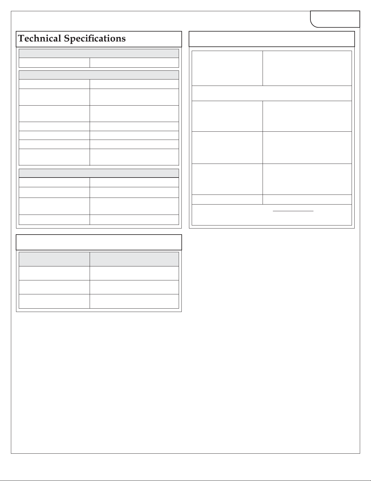
AMIK 300
Display update rate
Response time to step input
1 sec approx.
Applicable Standards
EMC IEC 61326
Immunity
Safety IEC 61010-1-2001 , Permanently
IP for water & dust IEC60529
Pollution degree
Installation category
High Voltage Test
IEC 61000-4-3. 10V/m min –
Level 3 industrial low level
connected use
2
III
2.2 kV AC, 50Hz for 1 minute
between all electrical circuits
VA Burden
Nominal input voltage burden
Nominal input current burden
Auxillary Supply burden
For VAC Aux. < 6.5 VA approx.
For DC Aux. < 3 W approx.
< 0.2 VA approx. per phase
< 0.6 VA approx. per phase
Default pulse rate
divisor
Other Pulse rate
Divisors (applicable only when Energy on MODBUS (RS-485) is in W)
10
100
1000
Pulse duration
*No. of Pulses = Maximum Pulses
CT Ratio
Where, CT Ratio = (CT primary/ CT Secondary)
CT secondary = 1A Max pulse rate
3600 pulses/Ah *
CT secondary = 5A Max pulse rate
720 pulses/Ah
CT secondary = 1A Max pulse rate
3600 pulses/10Ah *
CT secondary = 5A Max pulse rate
720 pulses/10Ah
CT secondary = 1A Max pulse rate
3600 pulses/100Ah *
CT secondary = 5A Max pulse rate
720 pulses/100Ah
CT secondary = 1A Max pulse rate
3600 pulses/1000Ah *
CT secondary = 5A Max pulse rate
720 pulses/1000Ah
60 ms, 100 ms or 200 ms
PT Secondary Ranges for Various Input Voltage
Input Voltage PT Secondary Settable Range
110V L-L (63.5V L-N) 100V – 120V L-L (57V – 69V L-N)
230V L-L (133V L-N) 121V – 239V L-L (70V – 139V L-N)
415V L-L (239.6V L-N) 240V – 480V L-L (140V – 277V L-N)
Page 4 of 7
Revision 2018/3
Page 6

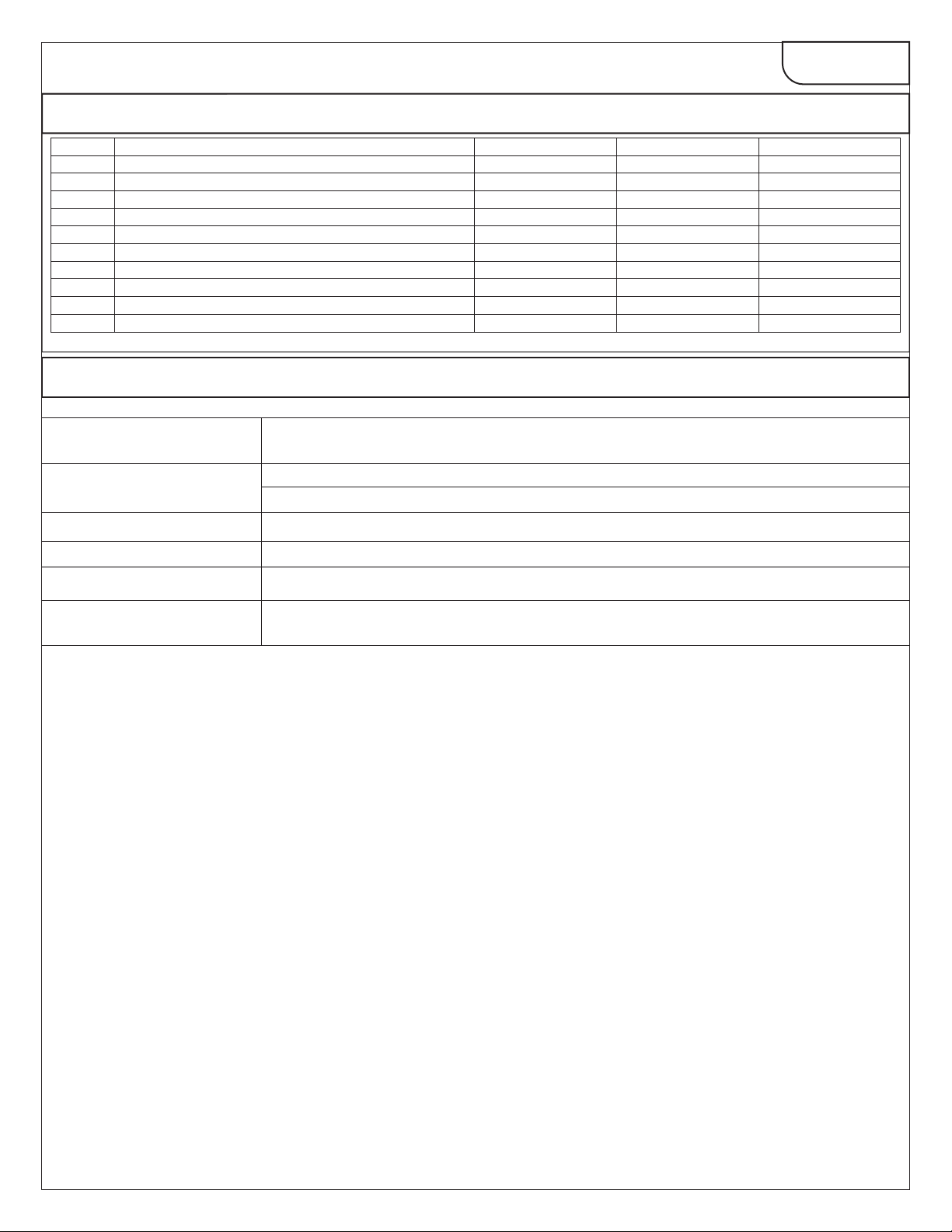
Electrical Parameters
AMIK 300
Sr No
1.
2.
3.
4.
5.
6.
7.
8.
9.
10. Current L2
11.
12.
13.
14.
15.
16.
17.
18.
19.
20.
21.
22.
23.
24.
25.
26.
27.
28.
29.
30.
31.
32.
33.
34.
35.
36.
37.
38.
39.
40.
41.
42.
43.
44.
45.
46.
47.
48. On Hour
49.
50.
51.
52.
53.
9 : Available 8 : Not Available
Displayed Parameters
System Volts
System Current
Volts L1 – N
Volts L2 – N
Volts L3 – N
Volts L1 – L2
Volts L2 – L3
Volts L3 – L1
Current L1
Current L3
Neutral Current
Frequency
System Active Power (kW)
Active Power L1 (kW)
Active Power L2 (kW)
Active Power L3 (kW)
System Re-active Power (kVAr)
Re-active Power L1 (kVAr)
Re-active Power L2 (kVAr)
Re-active Power L3 (kVAr)
System Apparent Power (kVA)
Apparent Power L1 (kVA)
Apparent Power L2 (kVA)
Apparent Power L3 (kVA)
System Power Factor
Power Factor L1
Power Factor L2
Power Factor L3
Phase Angle L1
Phase Angle L2
Phase Angle L3
Import kWh (8 digit resolution)
Export kWh (8 digit resolution)
Import kVArh (8 digit resolution)
Export kVArh (8 digit resolution)
kVAh (8 digit resolution)
KAh (8 digit resolution)
Current Demand
KVA Demand
KW Import Demand
KW Export Demand
Max Current Demand
Max KVA Demand
Max KW Import Demand
Max KW Export Demand
Run Hour
Number of Interruptions
Phase Reversal Indication
Phaser Diagram (Pictorial Representation)
VA waveform (Pictorial Representation)
THD Volts L1-N
3 Phase 4Wire 3Phase 3Wire
999
999
9
9
9
99
99
99
99
99
99
9
999
999
9
9
9
999
9
9
9
999
9
9
9
999
9
9
9
9
9
9
999
999
999
999
99
999
999
999
999
999
999
999
999
999
999
999
999
9
9
9
9
88
88
88
88
88
88
88
88
88
88
88
88
88
88
88
88
8
88
88
88
8
8
88
Single Phase 2W
8
8
8
8
8
8
9
9
9
9
Page 5 of 7
Revision 2018/3
Page 7
Electrical Parameters
AMIK 300
Sr No
54.
55.
56.
57.
58.
59.
60.
61.
62.
63.
9 : Available 8 : Not Available
Displayed Parameters
THD Volts L2-N
THD Volts L3-N
THD Volts L1-L2
THD Volts L2-L3
THD Volts L3-L1
THD Current L1
THD Current L2
THD Current L3
THD Voltage Mean
THD Current Mean
Ordering Information
Product Code Amik 300 (Without MODBUS)
Amik 301 (With MODBUS)
System Type 3 Ph. (PR. 3W or 4W)
Input Voltage
Input Current
Power Supply
1 Ph.
440V L-L
1/5A
100 V – 250 VAC / DC ± 10%
3 Phase 4Wire 3Phase 3Wire
9
9
8
8
8
9 9
9 9
9 9
9 9 9
9 9 9
Catalog No. A300
Catalog No. A301
8 8
8 8
9
9
9
Single Phase 2W
8
8
8
8
8
8
RS 485 & 4-20 mA
Analnog Output
RS 485 & 4-20 mA included in Model Amik 301.
Page 6 of 7
Revision 2018/3
Page 8

 Loading...