

Page 1
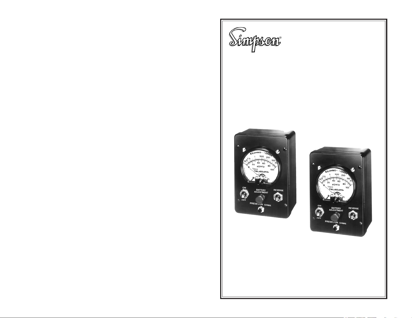
Simpson 8455 V3 And 8455A
Line Loop Testers
OPERATOR’S MANUAL
Model 8455 V3
Model 8455A
SIMPSON ELECTRIC COMPANY 520 Simpson Avenue
Lac du Flambeau, WI 54538-0099 (715) 588-3311 FAX (715) 588-3326
Printed in U.S.A. Part No. 06-115458 Edition 4, 05/07
Visit us on the web at: www.simpsonelectric.com
20
Page 2

About this Manual
To the best of our knowledge and at the time written, the information contained in
this document is technically correct and the procedures accurate and adequate
to operate this instrument in compliance with its original advertised specifications.
Notes and Safety Information
This Operator’s Manual contains warning symbols which alert the user to check
for hazardous conditions. These appear throughout this manual where applicable, and are defined below. To ensure the safety of operating performance of
this instrument, these instructions must be adhered to.
Warning, refer to accompanying documents.
Caution, risk of electric shock.
This instrument is designed to prevent accidental shock to the operator when
properly used. However, no engineering design can render safe an instrument
which is used carelessly. Therefore, this manual must be read carefully and completely before making any measurements. Failure to follow directions can result
in a serious or fatal accident.
Technical Assistance
SIMPSON ELECTRIC COMPANY offers assistance Monday through Friday
8:00 am to 4:30 pm Central Time. To receive assistance contact Technical Support or Customer Service at (715) 588-3311.
Internet: http://www.simpsonelectric.com
Warranty and Returns
SIMPSON ELECTRIC COMPANY warrants each instrument and other articles
manufactured by it to be free from defects in material and workmanship under
normal use and service, its obligation under this warranty being limited to making
good at its factory or other article of equipment which shall within one (1) year
after delivery of such instrument or other article of equipment to the original
purchaser be returned intact to it, or to one of its authorized service centers, with
transportation charges prepaid, and which its examination shall disclose to its
satisfaction to have been thus defective; this warranty being expressly in lieu of
all other warranties expressed or implied and of all other obligations or liabilities
on its part, and SIMPSON ELECTRIC COMPANY neither assumes nor authorizes any other persons to assume for it any other liability in connection with the
sales of its products.
This warranty shall not apply to any instrument or other article of equipment
which shall have been repaired or altered outside the SIMPSON ELECTRIC
COMPANY factory or authorized service centers, nor which has been subject to
misuse, negligence or accident, incorrect wiring by others, or installation or use
not in accord with instructions furnished by the manufacturer.
NOTES
2
19
Page 3

NOTES
NOTES
18
3
Page 4

Contents
1. INTRODUCTION ............................................................................... 5
2. ITEMS AND ACCESSORIES ............................................................ 5
3. TECHNICAL DATA ............................................................................. 6
4. UNPACKING AND INSPECTION ....................................................... 6
5. ELECTRICAL CHECKOUT ................................................................ 6
6. WARRANTY ...................................................................................... 7
7. SHIPPING ......................................................................................... 7
8. CONTROLS, CONNECTORS AND INDICATOR ................................. 7
9. SAFETY PRECAUTIONS .................................................................. 8
10. OPERATION ...................................................................................... 9
10.1 Mechanical Zero Adjustment ..............................................................9
10.2 Battery Adjustment (Resistance Ranges) ..........................................9
10.3 Storage and/or Transport .................................................................... 9
10.4 R⫼10 Push-button (8455 V3) ...........................................................1 0
10.5 Reverse Switch .................................................................................1 0
11. TEST FOR GROUND ...................................................................... 10
12. TEST FOR SHORT CIRCUIT .......................................................... 10
13. TEST FOR CROSSED CONDUCTORS ........................................... 11
14. TEST FOR OPEN ........................................................................... 11
15. TEST FOR SPLIT ........................................................................... 12
15.1 Identify Split Conductor of Line #2. ..................................................12
15.2 Identify Split Conductor of Line #1. ..................................................13
16. TEST FOR VOLTAGE ...................................................................... 13
17. CALCULATING DISTANCE TO FAULT ............................................. 13
18. OPERATOR MAINTENANCE .......................................................... 14
18.1 Inspection For Damage Or Deterioration .........................................14
18.2 Access To Battery Or Switches ......................................................... 15
18.3 Battery Replacement ........................................................................ 15
18.4 Switch Replacement ........................................................................15
18.5 Care ..................................................................................................1 6
NOTES
4
17
Page 5

18.5 Care
1. When the Instrument is not in use, set the ON/OFF switch to OFF to prevent
battery discharge if the test lead clips should accidentally be shorted together.
2. If the Instrument is to be stored for more than one month, remove the battery
to avoid corrosion damage.
3. Instruments subjected to rough handling and/or transport should be checked
frequently for specified accuracies. If such facilities are not available. the
Instrument may be sent to the factory Service Department for an overall
checkout, repair, if needed, and calibration.
!
When an Instrument must be stored and/or transported in a vehicle in very cold
weather, it will be subject to condensation when brought into a warm building.
Therefore, do not attempt high voltage measurements until certain that the Instrument is completely dry.
1. INTRODUCTION
The Simpson 8455 Line Loop Testers (hereafter referred to as the 8455 or the
Instrument) were specifically designed to analyze telephone line faults. Compact, rugged, and easy-to-use, they are capable of measuring DC voltage to 100
volts and loop resistances to 2M⍀ (8455 V3) or 10K⍀ (8455A). The voltmeter
function can be used to detect and measure any DC voltage on the line and the
resistance ranges can be used to identify and locate line faults.
The meter is of pivot-and-jewel construction with a 2-3/8" diameter dial with knifeedge pointer that moves across a 2-3/16" (100°) scale arc. Scales are as follows:
POINTS: 0-100 for ballistic tests
M⍀-K⍀: (8455 V3) 0-2M⍀ or 0-200k⍀ ranges; 0-10K⍀ (8455A)
VOLTAGE: 0-100 POINTS = 0-100V
Due to the 0-100° scale arc and the 0-100 dial calibrations, the accuracies of
±2% of full scale and ±2° of scale arc are both represented by ±1 scale division of
the POINTS scale anywhere on the scale.
The 8455A differs from the 8455 V3 in that it substitutes a 0-10K⍀ range for the 0200K⍀ range of the 8455 V3. The 2M⍀ range remains for points measurements,
but does not have a separate meter dial scale.
The 8455 V3 differs from earlier 8455 in that it incorporates a field replaceable
switch design. The 8455A shares the field replaceable switch design.
Throughout this manual, “8455” will now refer to both the 8455 V3 and the 8455A,
unless otherwise noted.
2. ITEMS AND ACCESSORIES
Table 2-1. Items and Accessories Furnished With This Instrument
16
Quantity Description Number
1 Test Lead Set 45001
1 Battery, 45V, NEDA, Type 201 6-113313
1 Operator’s Manual 6-115458
1 Carrying Case 00836
Table 2-2. Other Available Accessories
Description Number
Carrying Case, Leatherette M00674
Extra Test Lead Set 45001
Replacement Toggle Switch Boards (set of 10) 45025
Replacement Push-button “Reverse” Switch Boards (set of 10) 45026
TEST LEADS
The test lead set consists of one each, red and black, flexible test leads, 6 feet
long with Telco clips at one end and ring-tongue connectors at the other end for
connection to the Instrument’s screw terminals.
5
Page 6

3. TECHNICAL DATA
Table 3-1. Technical Data
1. DC Volts:
Range: 0-100V (0-100 POINTS)
Sensitivity: 1000⍀/V (8455 V3), 3333⍀/V (8455A)
Accuracy: ±2% of full scale (FS).
2. Resistance:
egnaR
1XRk001 ⍀ M2-0 ⍀ crafo°2±V84Am54.0
R⫼ 01k01 ⍀ k0
SMHO005 ⍀ k01-0 ⍀ crafo°2±V2.1Am4.2
retneC
elacS
3. Ballistic Tests: (Capacitive kick in POINTS) (Typ)
Capacity (µF) .5 1 1.5 2 2.5 3 3.5 4
POINTS kick 39 61 77 89 99 25* 29* 32*
* With R⫼10 push-button depressed (8455 V3 only)
4. Size
Case only: 3-5/8" W x 5-1/2" L x 2-1/2" H
Overall: 3-5/8" W x 5-1/2" L x 3" H
5. Weight: 1 lb. (0.45kg) (approx.)
6. Rated Circuit-ToGround Voltage*: 100 V DC
* Per ANSI C39-5, April, 1974: The maximum voltage, with respect to ground,
which may be safely and continuously applied to the circuits of an instrument.
gnirusaeM
egnaRycaruccA
02-0 ⍀ crafo°2±V84Am5.4
nepO.xaMV
.tkC
18.2 Access To Battery Or Switches
1. Disconnect the test leads from any circuitry.
2. Remove the four screws, one near each corner of the front panel (refer to
item 8 in Figure 3-1), and carefully lift the panel assembly, the cushioning
pad and the battery out of the case. The battery and switches will now be
accessible for service.
3. Replace the panel. Place the cushioning pad between the circuit board and
the battery, dressing the battery leads so they will not be pinched between
.tkCtrohSI
)pyT(
the panel and case when the panel screws are tightened.
18.3 Battery Replacement
1. When the BATTERY ADJUSTMENT control can no longer adjust the meter to
zero kilohms in both ranges, replace the battery.
2. Remove the panel from the case in accordance with paragraph 18.2.
3. Disconnect the leads from the battery and attach them to the new battery, red
lead to the “+” terminal and black lead to the “–” terminal.
4. The correct battery to be used with this Instrument is a 45V, NEDA type 201,
Eveready type 455, 2-31/32" x 1" x 3-11/64".
5. Battery condition can be checked on the 8455 V3 by setting the ON/OFF
switch to OFF (REVERSE switch to normal) and touching red test lead clip to
battery “+” terminal. A meter indication of at least 35 POINTS (35 V) is required for resistance measurements. A new battery will indicate about 48
POINTS (48 V).
6. On the 8455A, the battery must be removed before testing with the volts
function.
7. Replace the panel. Place cushioning pad between circuit board and battery,
dressing battery leads so they will not be pinched between the panel and
case when panel screws are tightened.
4. UNPACKING AND INSPECTION
Before unpacking, examine the shipping carton for signs of damage. If the carton
is damaged, unpack and inspect the Instrument. If the Instrument is damaged,
notify the carrier or supplier immediately.
Check that all items and accessories are included with the instrument as listed in
Table 2-1.
5. ELECTRICAL CHECKOUT
After determining that the 8455 is undamaged, check the Instrument for electrical
performance.
a. Install the battery supplied with the Instrument. If necessary, refer to the bat-
tery replacement procedure (page 17, paragraph 18.3).
b. Connect the ring-tongue connectors of the test leads to the Instrument screw
terminals. Connect the red test lead to the right screw and the black test lead
to the left screw. With these connections, the polarity color coding of the test
leads will be correct when the REVERSE switch is set to its normal position
(opposite from REVERSE).
6
18.4 Switch Replacement
To replace the switch:
1. Remove test leads and the four screws located near
meter face from the front cover (figure 18.4-1).
2. Detach the mounting nut from the defective toggle
switch (Figure 18.14-2).
3. Unplug the worn-out or broken switch and plug in a
new one (Figure 18.14-3).
4. Replace the panel. Place the cushioning pad between the circuit board and the battery, dressing the
battery leads so they will not be pinched between
the panel and case when the panel screws are tightened.
Push-Button Style
also available
Figure 18-3
LINE IN
1
3
CURRENT X1 FMR
SCHEMATIC
2
12
4
TYPICAL WIRING ARRANGEMENT
50mA - 50 Amps
LINE IN
34
METER RELAY
15
Figure 18-1
VANE TYPE 5 AMP
AC AMMETER
MODEL 816 CURRENT
TRANSFORMER 5 AMP
PRIMARY CAT. 01312
1
LINE LOAD
DONUT TRANSFORMER
WITH 5A SECONDARY
4
X
3
2
Figure 18-2
METER OR
RELAY
Page 7

loop resistance (the two conductors in series).
e. The resistance to the fault is the loop resistance divided by 2. To calculate the
distance to the fault in feet, refer to the table below for feet per ohm of resistance.
Table 5. Feet Per Ohm of Resistance
eguaGrotcudnoC).xorppa(mhOrePteeF
91521
c. Short the test clips together and set the ON/OFF switch to ON. The meter
should indicate upscale.
d. Adjust the BATTERY ADJUSTMENT control until the meter pointer rests over
the 100 POINTS mark on the scale. If this cannot be done, the battery is likely
weak. Refer to Section 18, for battery testing and replacement instructions.
e. While holding the R⫼10 button depressed (8455 V3 only), Repeat step “d”.
f. Set the ON/OFF switch to OFF and connect the test clips to a battery or low
voltage (less than 100V DC) source to assure that the voltage (POINTS)
range is functioning correctly.
2226
4204
6252
f. Select the “Feet Per Ohm” value for the line conductor gauge and multiply it
by the resistance to the fault.
Distance to Fault =
g. The actual distance may be shorter than calculated due to the unknown
resistance of the fault itself, if any, which will be included in the loop resistance.
h. When calculating distance to a ground fault (refer to table 5), only one con-
ductor is being measured. Do not divide the measured value by 2. Consider
the possible additional error that may be due to the unknown resistance of
the ground path as well as that of the fault.
Loop Resistance x Feet Per Ohm
2
18. OPERATOR MAINTENANCE
This section describes how to maintain the Instrument in good operating condition. This Instrument is carefully designed and constructed with high quality components. By providing reasonable care and following instructions in this manual,
the user can expect a long service life of the Instrument.
Servicing, other than described in this Section, should be performed only by one
of the Authorized Service Centers, or by the factory.
6. WARRANTY
The Simpson Electric Company warranty is printed on the inside front cover of
this manual. Read it carefully before requesting any warranty repairs.
NOTE: For all assistance, contact the nearest Simpson Authorized Service Center.
7. SHIPPING
Pack the Instrument carefully, and ship it prepaid and insured.
8. CONTROLS, CONNECTORS AND INDICATOR
This section describes the 8455 front
panel controls and its features. Become familiar with each control and
its function before using the Instrument.
Item numbers in Table 8-1 correspond
to the identifying numbers in Figure 8-
1.
Figure 8-1. Front Panel Controls
5
6
1
4
7
2
18.1 Inspection For Damage Or Deterioration
Examine the Instrument and its test leads frequently for damaged or deteriorated
insulation that may expose internal metal parts that may be a shock hazard.
Replace any damaged components before using the Instrument or allowing others to use it.
If the Instrument panel and/or test leads become soiled, clean them with a clean
rag dampened with a mild, detergent-water solution. Rinse with a clean water
dampened cloth, and dry thoroughly. Do not allow liquid to enter the Instrument
case.
14
3
Table 8-1. Controls, Connectors and Indicator
1. ON/OFF Switch: Selects the voltmeter function (OFF) or the resis-
tance measuring function (ON). In the ON position,
the internal battery is connected to energize the resistance function.
2. REVERSE Switch: Transposes the test lead connections to reverse po-
larity (both functions).
8
7
Page 8

3. a. R
CONDUCTORS OPENED FOR TEST
R
T
FAULT
R
T
TO
STAT I ON
TO
CENTRAL
OFFICE
8455
GROUND
*
LINE IN TROUBLE
OFF
CONDUCTORS OPENED FOR TEST
R
T
FAULT
R
T
TO
STAT I ON
TO
CENTRAL
OFFICE
ON
8455
LOOP RESISTANCE
⫼⫼
⫼10 Push-button:
⫼⫼
(8455 V3) Changes resistance range from 0-2M⍀ to 0-200k⍀
while depressed.
b. Press For Ohms
Push-button:
(8455A) Ohms function when depressed; points function
when released.
4. Test Lead
Connections: Screw terminals to which the test leads are con-
nected.
5. Battery Adjustment: Control to enable correction for battery condition
when calibrating resistance measuring ranges (zero
k⍀ adjustment).
NOTE: The Model 8455A ohms range is internally calibrated and is not affected
by the battery adjustment control.
6. Indicating Meter: Displays measured values of resistance (M⍀-K⍀),
(8455 V3) or (k⍀-⍀) 8455A, POINTS (ballistic tests)
or DC voltage (100 POINTS = 100V).
7. Mechanical Zero
Adjuster: This screwdriver adjustment corrects minor me-
chanical disturbances to the indicator’s zero position (when electrically de-energized).
8. Case Assembly
Screws (4): Screws to be removed to access battery.
9. SAFETY PRECAUTIONS
The following safety symbols may be found in this manual and/or on the Instrument. They call attention to procedures, practices or conditions which, if not correctly performed, adhered to, or observed, could result in:
15.2 Identify Split Conductor of Line #1.
a. Remove the strap from line #1 at the near end.
b. Connect one test clip to the split conductor of line #2 (identified in Paragraph
15.1, step f.).
c. Connect the other test clip first to one conductor of line #1 and then the other
conductor. The conductor that does not cause a deflection of the meter is the
split conductor of line #1.
16. TEST FOR VOLTAGE
a. Open line in trouble to-
ward Central Office.
b. Set the Instrument to mea-
sure voltage (ON/OFF
switch to OFF).
c. Connect one test clip to
ground*.
*GROUND: A connection to
metallic cable sheath or wrap,
to cable suspension strand, to
ground rod, or to grounded (T)
conductor of an adjacent pair.
d. Connect the other test clip to one conductor and then to the other. If the meter
deflects to the left of zero, the polarity is incorrect. Set the REVERSE switch to
its other position to obtain an up-scale reading.
e. The meter will indicate the value of any DC voltage that may be present on a
line conductor (with respect to ground) or, by connecting the clips to both
conductors, any voltage present across the line. (100 POINTS = 100 volts).
NOTE: The Instrument will not indicate the presence of AC voltage.
f. When the REVERSE switch is in the normal position (opposite to the RE-
VERSE position) and the meter deflects upscale, the polarity of the voltage is
positive (+) at the red test lead if the leads have been connected to the
Instrument properly (refer to page 8, Section 5, step b.).
Figure 16-1. Test for Voltage
Damage to the Instrument and/or equipment under test.
Injury to Persons
This Instrument is designed to prevent accidental shock to the operator when
properly used. However, no engineering design can guarantee how safe an
instrument is if used carelessly. Therefore, this manual must be read carefully and
completely before making any measurements. Failure to follow directions can
result in a serious or fatal accident.
NOTE: The following precautions are suggestions and reminders of commonly
recognized safe practices to adopt and specific hazards to be avoided and
are not implied to be sufficient to safeguard untrained personnel in all circumstances.
8
17. CALCULATING DISTANCE TO FAULT
a. Open conductors toward
Central Office.
b. Set the Instrument to
measure resistance
(ON/OFF switch to ON;
“Press for Ohms” depressed, 8455A).
c. Short test clips together
and adjust BATTERY
ADJUSTMENT control
for meter reading of full
scale (100 POINTS).
d. Connect one test clip to each conductor. The resistance value indicated is the
Figure 17-1. Calculating Distance to Fault
1315
Page 9

to hold the R⫼10 push-button depressed during the test (8455 V3). The POINTS
value noted in this test is the reference value by which the open line will be
evaluated.
f. Move the test clip from the good conductor to the open conductor.
g. Repeat step “e”, except do not change the setting of the BATTERY ADJUST-
MENT control. Note the POINTS value of the meter deflection.
h. The relative values of the meter deflections in steps “e” and “g” indicate
approximate distance to the open.
i. The chart below provides a rough approximation of the distance to the open
for various deflection POINTS of the open line as a percentage of the deflection POINTS of the good line.
Open Line “POINTS” Approximate
(as % of good line “POINTS”) Distance To Open
100 ......................................... 100% of line length
90 ......................................... 80% of line length
80 ......................................... 60% of line length
60 ......................................... 45% of line length
40 ......................................... 30% of line length
20 ......................................... 15% of line length
10 ......................................... 10% of line length
5 ......................................... 5% of line length
1. The 8455 should only be used by personnel who are qualified to recognize
shock hazards and are trained in the safety precautions required to avoid
possible injury.
2. Do not connect any terminal of this Instrument to a circuit point at which a
voltage exceeding 100 volts DC may exist with respect to earth ground.
(Refer to Table 8-1, item 4).
3. This Instrument is intended only for indoor use or in sheltered outdoor locations. To prevent fire or shock hazards, do not expose Instrument to rain or
moisture.
4. Before using this Instrument, check both the Instrument and the test leads for
missing, damaged, deteriorated or faulty insulation. Do not use the instrument until it has been properly repaired.
5. DC voltages under 60V are not considered to be a shock hazard; however,
the meter is capable of measurements up to 100V. If the Instrument is to be
used to measure voltages exceeding 60V DC, precautions should be taken
to avoid bodily contact with the energized circuit.
6. Do not make electrical measurements where the air may contain explosive
concentrations of gas or dust such as in mines, grain elevators, gasoline
stations or in the presence of charging batteries, until determined to be safe
by qualified personnel. Note that even metallic dust can be explosive.
7. Do not use this Instrument to make electrical measurements on blasting
circuits or blasting caps.
15. TEST FOR SPLIT
15.1 Identify Split Conductor of Line #2.
LINE # 1
LINE # 2
FAULT
STRAP
R
T
FAR
END
R
T
CONDUCTORS OPENED FOR TEST
R
X
STRAP
X
X
X
8455
ON
NEAR
END
T
R
T
Figure 15-1. Test for Split
a. Open all four conductors at the near end.
b. Strap short across line #1 at the near end.
c. Strap short across line #1 at the far end.
d. Set the Instrument to measure resistance (ON/OFF switch to ON; “Press for
Ohms” depressed, 8455A).
e. Connect one test clip to strapped connection of line #1.
f. Connect the other test clip first to one conductor of line #2 and then the other
conductor. The conductor that causes a deflection of the meter is the split
conductor of line #2.
10. OPERATION
10.1 Mechanical Zero Adjustment
For accuracy of all measurements, the meter pointer must rest directly over the 0
POINTS mark at the left end of the dial scale when the ON/OFF switch is set to the
OFF position. If the pointer is not in that position, rotate the mechanical zero adjust
screw (Figure 8-1, item 7) in either direction until it does.
10.2 Battery Adjustment (Resistance Ranges)
For accuracy of resistance measurements, the meter pointer must rest directly
over the 100 POINTS mark at the right end of the dial scale when the ON/OFF
switch is set to the ON position and the test clips are shorted together. If the pointer
is not in that position, adjust the BATTERY ADJUSTMENT control (Figure 8-1,
item 5).
10.3 Storage and/or Transport
Keep the ON/OFF switch in the OFF position at all times except when making
measurements. This will prevent battery discharge in the event that the test clips
are accidentally shorted together during storage or transport.
NOTE: Before making a resistance or ballistics test, connect the Instrument to the
line with the ON/OFF switch in the OFF position (voltage measurement) to detect
the presence of unexpected DC voltages. The presence of DC voltages will cause
inaccurate test readings and may damage the meter.
12
9
Page 10

CONDUCTORS OPENED FOR TEST
R
T
FAULT
R
T
TO
STAT I ON
TO
CENTRAL
OFFICE
ON
8455
SHORT
TO
STAT I ON
T
R
T
CROSS
LINE # 2
LINE # 1
8455
ON
TO
CENTRAL
OFFICE
R
T
R
T
CONDUCTORS OPENED FOR TEST
FAULT
R
X
X
X
X
CONDUCTORS OPENED FOR TEST
R
T
FAULT
R
T
TO
STAT I ON
TO
CENTRAL
OFFICE
ON
8455
GROUND
*
X
X
CONDUCTOR CAPACITANCE
TO GROUND
OPEN
10.4 R
⫼⫼
⫼10 Push-button (8455 V3)
⫼⫼
This push-button is used for resistance measurements only. While the button is
depressed, the resistance range becomes 1/10 of the dial markings and the
indication is then divided by 10. For example, if the value indicated is less than 10
K⍀, the scale divisions are very small. By depressing the R⫼10 button, 0-10 K⍀ is
spread across 1/2 of the scale and a more accurate reading can be obtained. If, in
a ballistic test, the meter pointer kicks off-scale (past 100 POINTS), holding the
R⫼10 button will reduce the “kick” to a readable value.
10.5 Reverse Switch
This switch is primarily for convenience when making ballistic tests. Operating
the switch back and forth transposes the test leads to produce the capacitive
charging “kick” when connected to an open line conductor. It can also be used to
reverse the polarity of the test leads for voltage measurements.
NOTE: The Instrument can be operated in any convenient position; however,
maximum reading accuracy is obtained with panel in horizontal position as the
Instrument was calibrated in this position.
11. TEST FOR GROUND
a. Open conductors toward
Central Office.
b. Set the Instrument to mea-
sure resistance (ON/OFF
TO
CENTRAL
OFFICE
switch to ON; “Press for
Ohms” depressed, 8455A).
c. Short test clips together and
adjust BATTERY ADJUST-
MENT control for meter
reading of full scale (100
POINTS).
d. Connect one test clip to ground*.
*GROUND: A connection to metallic cable sheath or wrap, to cable suspension
strand, to ground rod, or to grounded (T) conductor of an adjacent pair.
e. Connect the other clip to conductor giving a meter deflection.
f. Note the exact value of resistance indicated. For resistance less than 10 k⍀,
hold R⫼10 button depressed and divide indicated value by 10 (8455 V3).
g. To calculate distance to fault, refer to Section 17.
12. TEST FOR SHORT CIRCUIT
a. Open conductors toward Central Office.
b. Set the Instrument to measure resistance (ON/OFF switch to ON; “Press for
Ohms” depressed, 8455A).
c. Short test clips together and adjust BATTERY ADJUSTMENT control for meter
reading of full scale (100 POINTS).
d. Check both conductors for grounds.
e. Connect test clips across line pair.
CONDUCTORS OPENED FOR TEST
R
T
8455
ON
Figure11- 1. Test for Ground
10
GROUND
f. Note the exact value of re-
sistance indicated. For resistance less than 10 K⍀, hold
R⫼10 button depressed
and divide indicated value
by 10 (8455 V3).
g. To calculate distance to fault,
refer to Section 17.
Figure 12-1. Test for Short Circuit
13. TEST FOR CROSSED CONDUCTORS
a. Open conductors toward
Central Office.
b. Set Instrument to measure
resistance (ON/OFF switch
to ON; “Press for Ohms” depressed, 8455A).
c. Short test clips together and
adjust BATTERY ADJUSTMENT control for meter
reading of full scale (100
FAULT
R
T
TO
STAT I ON
POINTS).
d. Connect test clips to combi-
Figure 13-1. Test for Crossed Conductors
nations of conductors until
a meter indication is obtained. These are the crossed conductors.
e. Note the exact value of resistance indicated. For resistance less than 10 K⍀,
*
hold R⫼10 button depressed and divide indicated value by 10 (8455 V3).
f. To calculate distance to fault, refer to Section 17.
14. TEST FOR OPEN
a. Open conductors toward
Central Office.
b. Set the Instrument to mea-
sure resistance (ON/OFF
switch to ON).
c. Connect one test clip to
ground*.
d. Connect the other test clip
to the good conductor (not
open).
e. Operate the REVERSE switch back and forth slowly (allow time for the pointer
to return to zero each time) and note maximum POINTS value of the momentary deflection of the meter.
*GROUND: A connection to metallic cable sheath or wrap, to cable suspension
strand, to ground rod, or to grounded (T) conductor of an adjacent pair.
NOTE: If meter deflects beyond 100 POINTS, try adjusting the BATTERY ADJUSTMENT control for a deflection of 100 POINTS. If this fails, it will be necessary
Figure 14-1. Test for Open
11
 Loading...