

Simpson Electric 260-8 Instruction Manual
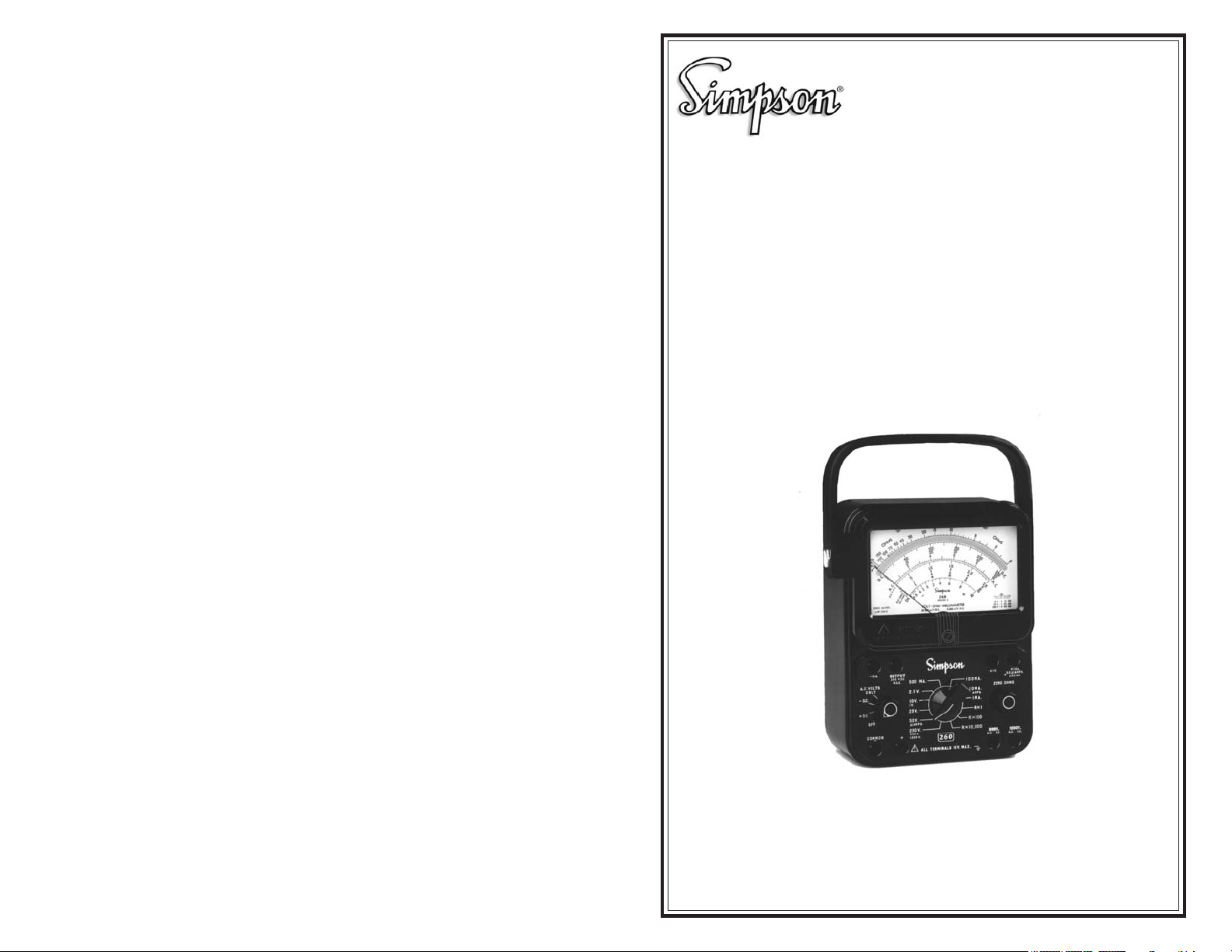
Simpson 260® Series 8
Volt-Ohm-Milliammeters
INSTRUCTION MANUAL
SIMPSON ELECTRIC COMPANY 520 Simpson Avenue
Lac du Flambeau, WI 54538-0099 (715) 588-3311 FAX (715) 588-3326
Printed in U.S.A. Part No. 06-114338 Edition 11, 07/07
Visit us on the web at: www.simpsonelectric.com
32

About this Manual
To the best of our knowledge and at the time written, the information contained in
this document is technically correct and the procedures accurate and adequate to
operate this instrument in compliance with its original advertised specifications.
Notes and Safety Information
This Operator’s Manual contains warning headings which alert the user to check
for hazardous conditions. These appear throughout this manual where applicable,
and are defined below. To ensure the safety of operating performance of this instrument, these instructions must be adhered to.
Warning, refer to accompanying documents.
Caution, risk of electric shock.
Technical Assistance
SIMPSON ELECTRIC COMPANY offers assistance Monday through Friday
8:00 am to 4:30 pm Central Time by contacting Technical Support or
Customer Service at (715) 588-3311.
Internet: http://www.simpsonelectric.com
Warranty and Returns
SIMPSON ELECTRIC COMPANY warrants each instrument and other articles
manufactured by it to be free from defects in material and workmanship under
normal use and service, its obligation under this warranty being limited to making
good at its factory or other article of equipment which shall within one (1) year
after delivery of such instrument or other article of equipment to the original purchaser be returned intact to it, or to one of its authorized service centers, with
transportation charges prepaid, and which its examination shall disclose to its
satisfaction to have been thus defective; this warranty being expressly in lieu of all
other warranties expressed or implied and of all other obligations or liabilities on
its part, and SIMPSON ELECTRIC COMPANY neither assumes nor authorizes
any other persons to assume for it any other liability in connection with the sales
of its products.
NOTES
This warranty shall not apply to any instrument or other article of equipment which
shall have been repaired or altered outside the SIMPSON ELECTRIC COMPANY
factory or authorized service centers, nor which has been subject to misuse, negligence or accident, incorrect wiring by others, or installation or use not in accord
with instructions furnished by the manufacturer.
®
is a Registered Trademark of the Simpson Electric Co.
260
2
31

NOTES
NOTES
30
3

Contents
1 INTRODUCTION ................................................................................. 6
1.1 General Description ............................................................................. 6
1.2 Overload Protection ............................................................................. 6
1.3 Internal Batteries .................................................................................. 7
1.4 Printed Circuit ....................................................................................... 7
1.5 Phenolic Case ....................................................................................... 7
1.6 Adjust-A-Vue Case ................................................................................ 7
1.7 Test Leads ............................................................................................. 7
1.8 Technical Data .......................................................................................8
1.9 Definition of Accuracy .......................................................................... 9
1.10Safety Considerations .......................................................................... 9
2 INSTALLATION ................................................................................. 12
2.1 General ................................................................................................ 12
2.2 Unpacking and Inspection ................................................................. 12
2.3 Warranty .............................................................................................. 12
2.4 Power Source Requirements ............................................................. 12
2.5 Operating Position .............................................................................. 12
3 CONTROLS, JACKS AND INDICATORS ......................................... 13
3.1 General ................................................................................................ 13
3.2 Front Panel Description ..................................................................... 13
4 OPERATION ..................................................................................... 14
4.1 General ................................................................................................ 14
4.2 Safety Precautions ............................................................................. 14
4.3 Polarity Reversing .............................................................................. 15
4.4 Measurement of Unknown Voltage or Current ................................. 15
4.5 Test Leads ........................................................................................... 15
4.6 DC Voltage Measurement 0-250mV Range ....................................... 16
4.7 DC Voltage Measurement 0-1V Range ............................................... 16
4.8 DC Voltage Measurement 0-2.5 ~ 0-250V Range .............................. 17
4.9 DC Voltage Measurement 0-500V Range ........................................... 17
4.10DC Voltage Measurement 0-1000V Range ......................................... 18
4.11AC Voltage Measurement 0-2.5 ~ 0-250V Range .............................. 19
4.12AC Voltage Measurement 0-500V Range ........................................... 20
4.13AC Voltage Measurement 0-1000V Range ........................................21
4.14Output Voltage Measurement ............................................................. 22
4.15Decibel Measurement (–20 to +50 dB) ............................................. 23
4.16Direct Current Measurement ............................................................. 23
4.17Direct Current Measurement 0-50µA Range .................................... 24
4.18Direct Current Measurement 0-1mA through 0-500mA range ........ 24
4.19Direct Current Measurement 0-10A range ........................................24
4.20Resistance Measurements ................................................................. 25
4.21Measuring Resistance ........................................................................ 26
4.22Resistance Measurement of Semiconductors ................................. 26
5.6 Care
Immediately clean all spilled materials from the Instrument and wipe dry. If the
spillage is corrosive, use a suitable cleaner to neutralize the corrosive action.
Whenever the Instrument is not in use, rotate the function switch to the OFF position.
Whenever possible, avoid prolonged exposure or usage in areas which are subject to temperature and humidity extremes, vibration or mechanical shock, dust or
corrosive fumes, or strong electrical or electromagnetic interferences.
Verify Instrument accuracy by performing operational checks using known, accurate, stable sources. If proper calibration equipment is not available, contact the
nearest Authorized Service Center. If the Instrument has not been used for 30
days, check the batteries for leakage and replace if necessary.
It is recommended that the Instrument be returned annually to the nearest Authorized Service Center, or to the factory, for an overall check, adjustment, and calibration.
When the Instrument is not in use, store it in a room free from temperature extremes, dust, corrosive fumes, and mechanical vibration or shock. If storage time
is expected to exceed 30 days, remove batteries.
4
29

5.3 Battery Replacement
a. Two batteries are used inside the case to supply power for resistance mea-
surements. One is a 1.5-volt D cell and the other is a 9-volt battery. When it
is no longer possible to adjust the pointer to zero for the R X 1 and R X 100
ranges (refer to ZERO OHMS ADJUSTMENT paragraph 4.20), replace the
1.5-volt cell. When it is no longer possible to adjust the pointer to zero on the
R X 10,000 range, replace the 9-volt battery.
b. To install or replace a battery, de-energize and disconnect test leads from the
Instrument, then remove the cover to the externally accessible battery com-
partment by loosening the single captivated screw.
NOTE: Batteries should be replaced before their useful life has expired.
Failure to do so may result in corrosion and battery leakage.
c. Observe polarity when replacing the 1.5-volt D cell and connect as indicated.
The D cell is held in place with spring clips which also act as battery contact
clips. The 9-volt battery contacts and connector are polarized. To remove the
9-volt battery, first withdraw battery with mated connector from the compart-
ment. Then remove the connector.
5.4 Fuse Replacement
The 1 and 2 ampere fuse (also the 1A spare) is located in the externally accessible battery and fuse compartment. Access to the compartment is obtained by
disconnecting the test leads and loosening the single captivated screw on the
compartment cover. To replace or check a fuse: Apply pressure to the 1 amp fuse
cup then rotate the plate to expose a selected fuse for removal from the panel’s
cavity.
5 OPERATOR MAINTENANCE ......................................................... 27
5.1 General ................................................................................................ 27
5.2 Inspection ............................................................................................ 27
5.3 Battery Replacement .......................................................................... 28
5.4 Fuse Replacement .............................................................................. 28
5.5 Test Lead Inspection .......................................................................... 28
5.6 Care ...................................................................................................... 29
NOTE: When replacing fuses, it is important to use the same type and value as
the ones you have removed.
5.5 Test Lead Inspection
Periodic inspection of the test leads is recommended to detect cuts, burned areas, deterioration or other damage that could reduce the insulation strength of
leads.
28
5
 Loading...