

Page 1
OPERATOR’S MANUAL
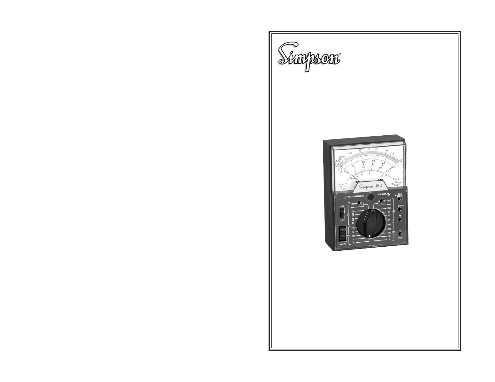
Model 160
Volt-Ohm-Milliammeter
SIMPSON ELECTRIC COMPANY 520 Simpson Avenue
Lac du Flambeau, WI 54538-0099 (715) 588-3311 FAX (715) 588-3326
Printed in U.S.A. Part No. 05-111658 Edition 16, 05/07
Visit us on the web at: www.simpsonelectric.com
16
Page 2

About this Manual
To the best of our knowledge and at the time written, the information contained in this document is technically correct and the procedures accurate
and adequate to operate this instrument in compliance with its original advertised specifications.
Notes and Safety Information
This Operator’s Manual contains warning symbols which alert the user to
check for hazardous conditions. These appear throughout this manual where
applicable, and are defined below. To ensure the safety of operating performance of this instrument, these instructions must be adhered to.
Warning, refer to accompanying documents.
!
Caution, risk of electric shock.
!
This instrument is designed to prevent accidental shock to the operator when
properly used. However, no engineering design can render safe an instrument which is used carelessly. Therefore, this manual must be read carefully
and completely before making any measurements. Failure to follow directions can result in a serious or fatal accident.
Technical Assistance
SIMPSON ELECTRIC COMPANY offers assistance Monday through Friday
8:00 am to 4:30 pm Central Time. To receive assistance contact Technical
Support or Customer Service at (715) 588-3311.
Internet: http://www.simpsonelectric.com
Warranty and Returns
SIMPSON ELECTRIC COMPANY warrants each instrument and other articles manufactured by it to be free from defects in material and workmanship
under normal use and service, its obligation under this warranty being limited
to making good at its factory or other article of equipment which shall within
one (1) year after delivery of such instrument or other article of equipment to
the original purchaser be returned intact to it, or to one of its authorized
service centers, with transportation charges prepaid, and which its examination shall disclose to its satisfaction to have been thus defective; this warranty
being expressly in lieu of all other warranties expressed or implied and of all
other obligations or liabilities on its part, and SIMPSON ELECTRIC COMPANY neither assumes nor authorizes any other persons to assume for it any
other liability in connection with the sales of its products.
This warranty shall not apply to any instrument or other article of equipment
which shall have been repaired or altered outside the SIMPSON ELECTRIC
COMPANY factory or authorized service centers, nor which has been subject
to misuse, negligence or accident, incorrect wiring by others, or installation
or use not in accord with instructions furnished by the manufacturer.
SHOCK HAZARD: As defined in American National Standard, C39.5, Safety
Requirements for Electrical & Electronic Measuring & Controlling Instrumentation, a shock hazard shall be considered to exist at any part involving a
2
and reverse the leads. The polarity switch must be kept in the + DC position on this range.
5. Read the current directly on the black arc marked DC, using the 0-50
scale. The current value is shown in microamperes.
6. Turn off power to the circuit. Remove the test leads and restore the circuit
continuity.
4.13 Measuring Direct Current, 0-1 Through 0-500 mA
Ranges
1. Connect the black test lead to the COM (–) jack and the red test leads to
the + jack. Set the polarity switch to the + DC position.
2. Set the range switch to any of the five mA direct current range positions,
as desired. The switch positions are marked 1 mA, 10 mA, 100 mA, 250
mA, and 500 mA. When in doubt as to which range to use, always start
with the highest ranges as a protection to the Instrument.
3. When the circuit power is turned off, open the circuit at the point where
current is to be measured. Connect the Instrument in series with the circuit, observing proper polarities.
4. Apply power to the circuit being measured. If the pointer deflects to the
left of zero, the polarity is reversed. Turn off the power. Set the polarity
switch to the –DC position and then reapply the power.
5. Read the current on the black scale marked DC, which is second from
the top of the dial.
mA Range Use Scale Reading
1.0 0-10 Divide by 10
10 0-10 Read direct value
100 0-10 Multiply reading by 10
250 0-2.5 Multiply reading by 100
500 0-50 Multiply reading by 10
6. Turn off power to the circuit. Remove the test leads and restore circuit
continuity.
5. BATTERY REPLACEMENT
When the Ohms Adjust control cannot be adjusted for zero ohms (with shorted
test leads), it is generally an indication that the battery must be replaced. Failure to do so promptly can result in damage to the 160 due to chemical leakage from the battery.
To replace the battery, remove the screw holding the back cover to front panel
and separate the back cover from the front panel. Loosen the screw securing
the battery contact plate located at the top of the 160 panel assembly, then
rotate the contact plate enough to allow removal of the batteries. When installing new batteries, note battery placement and polarity as indicated on
the contact plate.
15
Page 3
6. Connect the test leads across the resistance which is to be measured. If
there is a “forward” and “backward” resistance, such as with diodes, observe polarity in the lead connections to control each direction of test.
With the polarity switch in the + DC position, the + jack will provide a
positive potential referred to COM – jack. Setting the switch to the – DC
position will reserve this measuring potential.
7. Read the indication on the OHMS arc at the top of the dial. Note that the
arc reads from right to left for increasing values.
8. Multiply the reading by the multiplier factor indicated at the switch position; the result is the resistance value in ohms. “K” on the dial and panel
stands for “times one thousand”.
NOTE: The resistance of nonlinear components will measure as different values on different ranges of the 160. For example, a diode could measure 80
on the R x 1 range, and 300 on the R x 10 range. This is normal and is the
result of the diode characteristic. The difference in readings does not indicate
faulty operation of the ohmmeter circuit.
4.11 Direct Current Measurement
1. Do not switch the range setting of the Range or Polarity Switches while
the circuit under measurement is energized.
2. Never disconnect the test leads from the circuit under measurement while
the circuit is energized.
3. Always turn the power off and discharge all the capacitors before the
setting of the switches is changed, or the leads disconnected.
4. Never exceed the Circuit-To-Ground voltage of the Instrument (1,000 V
max: Table 1-1, Rated Circuit-Ground Voltage).
5. Always connect the Instrument in series with the ground side of the circuit.
6. In all direct current measurements make certain the power to the circuit
being tested has been turned off before connecting and disconnecting
test leads or restoring circuit continuity.
potential in excess of 30 volts RMS (sine wave) or 42.4 volts DC or peak and
where a leakage current from that part to ground exceeds 0.5 milliampere,
when measured with an appropriate measuring instrument defined in Section 11.6.1 of ANSI C39.5.
4.12 Measuring Direct Currents, 50
Never connect the test leads directly across any source of voltage when the
160 is used for current measurements. This will damage the Instrument.
1. Connect the black test lead to the COM – jack, and the red test lead to the
+ 50 mA jack.
2. Set the range switch at 50 mA (common with 50 VDC).
3. With the circuit power turned off, open the circuit at the point where current is to be measured. Connect the Instrument in series with the circuit,
observing proper polarities when making connection.
4. Turn on power to the circuit being measured. If the pointer is deflected to
the left of zero, the polarity is opposite to that anticipated. Turn power off
A Range
14
3
Page 4

Contents
4.8 Measuring AC Voltages, 1000 Volt Range Only
1. INTRODUCTION ................................................................................ 5
1.1 General ...............................................................................................5
1.2 Supplies & Accessories ...................................................................... 5
1.3 Safety Considerations ........................................................................5
1.4 Technical Data ....................................................................................5
2. INSTALLATION .................................................................................. 7
2.1 Unpacking & Inspection ..................................................................... 7
2.2 Warranty .............................................................................................. 7
2.3 Shipping .............................................................................................8
2.4 Operating Procedure .......................................................................... 8
3. CONTROLS, CONNECTORS & INDICATORS ................................... 8
3.1 Panel Description ............................................................................... 8
4. OPERATION...................................................................................... 9
4.1 Safety Precautions .............................................................................. 9
4.2 Zero Adjustment ............................................................................... 10
4.3 Measuring DC Voltages, 250 Millivolt Range .................................. 10
4.4 Measuring DC Voltages, 1 V Range .................................................11
4.5 Measuring DC Voltages, 2.5 Through 500 V Ranges ......................11
4.6 Measuring DC Voltages, 1,000 Volt Range Only .............................12
4.7 Measuring AC Voltages, 2.5 Through 500 Volt Range ....................12
4.8 Measuring AC Voltages, 1000 Volt Range Only ............................... 13
4.9 Measuring Decibels .........................................................................1 3
4.10 Measuring Resistance .....................................................................1 3
4.11 Direct Current Measurement ............................................................1 4
4.12 Measuring Direct Currents, 50 mA Range .......................................1 4
4.13 Measuring Direct Current, 0-1 Through 0-500 mA Ranges ............. 15
5. BATTERY REPLACEMENT ............................................................. 15
!
Use extreme care when working in high voltage circuits. Even though the
Instrument and test leads are well insulated for this voltage, do not handle
when power is on in the circuit.
1. Set the range switch at 1,000 VAC position (common with the 500 VAC
position).
2. Turn off power in the circuit being measured.
3. Connect the black test lead to the COM (–) jack, and the red test lead to
the 1,000 VAC jack.
4. Turn on power in the circuit being measured.
5. Read the voltage on the red arc marked AC using the 0-10 figures and
multiply the reading by 100.
4.9 Measuring Decibels
The decibel scale at the bottom of the dial is numbered from –20 to +10. To
measure decibels, proceed according to instructions for AC voltages, and
read the dB arc. The dB scale is calibrated for direct reading on the 2.5V
range. Scale factors for other ranges and dB reference at 0.006 watts into 500
ohms are given in the table below.
Range 1 mW @ 600 6 mW @ 500
2.5V direct –7
10 V +12 +5
50 V +26 +19
250 V +40 +33
4.10 Measuring Resistance
When resistances are measured, the internal batteries of the 160 furnish power
for the measuring circuit. Correction for battery deterioration over long periods of time is provided by means of the Zero Adjust control which is part of
the ohmmeter circuit.
1. Set the range switch at the desired resistance range position.
2. Connect the black test lead to the COM (–) jack, and the red test lead to
the + jack.
3. Connect the contact ends of the test leads together.
4. Observe the Instrument indication. Look for a reading of “0” on the OHMS
arc, which is at the top of the dial.
5. If the pointer does not read “0”, rotate the ZERO OHMS knob at the lower
left on the front panel until it does. If the pointer cannot be brought up to
the “0” mark, replace the appropriate battery.
NOTE: Disconnect power from any resistor or circuit to be measured before
measuring resistance. Do not apply any power until the measurements are
completed and test leads are disconnected.
4
13
Page 5

4.6 Measuring DC Voltages, 1,000 Volt Range Only
1. INTRODUCTION
1.1 General
!
Use extreme care when working in high voltage circuits. Even though the
Instrument and test leads are well insulated for this voltage, do not handle
when power is on in the circuit.
1. Set the range switch to the 1,000 VDC position (common with the 500
VDC position).
2. Connect the black test lead to the COM (–) jack and the red test lead to
the 1,000 VDC jack.
3. Set the polarity switch to the + DC position.
4. Connect the black test lead to the negative (–) side of the circuit and the
red test lead to the positive (+) side.
5. If the pointer deflects to the left side of zero, the actual circuit polarity is
the reverse of that anticipated. (In this case see Paragraph 4.5, step d.)
6. Read the voltage, using the 0-10 scale on the black arc marked DC and
multiply the reading by 100.
4.7
Measuring AC Voltages, 2.5 Through 500 Volt
Range
The 160 rectifier circuit responds to the full wave rectified average value of
the AC voltage being applied. The Instrument dial, however, is calibrated in
terms of RMS voltage, which will be correct for all sinusoidal waveforms.
NOTE: Since the 160 will respond to DC voltage when set on any AC volt
range an external blocking capacitor must be employed where measurements
of AC superimposed on DC are encountered.
1. Connect the black test lead to the COM – jack and the red test leads to
the + jack.
2. Set the range switch for any of the five VAC range positions desired. These
are marked 2.5 VAC, 10 VAC, 50 VAC, 250 VAC, and 500 VAC. When in
doubt as to which range to use, always start with the highest voltage
range as a protection to the Instrument.
3. Turn the power on in the circuit to be tested. Read the voltage on the red
arc marked AC.
0-2.5 VAC range: Read the value directly on the special arc marked
2.5 VAC.
10 and 50 VAC ranges: Read the red arc marked AC, and use the corre-
sponding black numbers immediately below the arc.
250 VAC range: Read the red arc marked AC using the 0-2.5 figures
and multiply the reading by 100.
500 VAC range: Read the red arc marked AC using the 0-50 figures
and multiply the reading by 10. If the voltage is within
a lower range, the switch may be set for the lower
range to obtain a more accurate reading.
12
The Simpson 160 Volt-Ohm-Milliammeter (hereafter referred to as the 160 or
the Instrument) is a compact, easy-to-operate instrument used for measuring
electrical characteristics of circuits and circuit components. The Instrument
has a taut-band movement suspension with diode overload protection to provide long, trouble-free service. The 100 degree mirrored dial arc and knife
edge pointer provide excellent readability and eliminate parallax errors.
A polarity-reversing switch and a one-knob Function/Range selector simplify
operation of the Instrument. The internal batteries are easily obtained and
replaced.
Most of the component parts are mounted on a printed circuit board. This
helps ensure uniform performance, reduces maintenance and extends the
useful life of the Instrument.
1.2 Supplies & Accessories
All supplies and accessories required for the operation of the 160 are furnished with each Instrument and listed in Table 1-2.
1.3 Safety Considerations
This Operator’s Manual contains cautions and warnings alerting the user to
hazardous operating and service conditions. CAUTION or WARNING symbols are placed throughout this publication, where applicable, and are defined on the inside cover of the manual under the heading SAFETY SYMBOLS. Adherence to these instructions will help ensure safety of operating
and servicing personnel and protect the instrument.
1.4 Technical Data
Table 1-1. Technical Data
DC Volts
Ranges: 2.5, 10, 50, 250V; 0.25, 1.0 and 1000V on sepa-
rate jacks.
Sensitivity: 20,000 per volt
Rated Accuracy: Within 2% DC and 3% AC of full scale on all
ranges.
AC Volts:
Ranges: 2.5, 20, 50, 250, 500V; 1,000V on separate jack.
Sensitivity: 5,000 per volt.
Indication: Full-wave average-responding: calibrated in RMS
for sinusoidal waveforms.
* Frequency Response: Rated accuracy to 100,000 Hz on all ranges
through 50V; to 20 kHz on 250V range. 2-A.
** Rated CircuitTo-Ground Voltage: 1,000V AC/DC max.
5
Page 6

* See typical Response Curves, Figure 1-1.
** Per ANSI C39.5 April 1974: “The maximum voltage with respect to ground,
which may safely and continuously be applied to the circuit of an instrument.”
Direct Current:
Ranges: 1, 10, 100, 250, 500 mA; 50 A on separate jack.
Rated Accuracy: Within 2% full scale, all ranges
RESPONSE (dB) RELATIVE TO 10KC
+3
250VAC RANGE:
50VAC RANGE:
+2
10 VAC RANGE:
25 VAC RANGE:
+1
SPEC. LIMITS:
0
-1
-2
-3
10 100 1000
250V RANGE
50V RANGE
10K 100K
CYCLES PER SECOND
1M
2.5 & 10V
RANGES
Figure 1-1. Typical Frequency Response Curve
DC Resistance
Ranges:
R x 1 0-3,000 (30 center)
R x 10 0-30,000 (300 center)
R x 100 0-300,000 (3 K center)
R x 1K 0-3 M (30 K center)
R x 10K 30 M (300 K center)
Accuracy: 3° arc
Max. Voltage or Current
Delivered:
R x 1 50 mA short circuit, 1.5V open circuit
R x 10 5 mA short circuit, 1.5V open circuit
R x 100 0.5 mA short circuit, 1.5V open circuit
R x 1K 0.75 mA short circuit, 22.5V open circuit
R x 10K 0.075 mA short circuit, 22.5V open circuit
dB Ranges: –20 dB to +10 dB on 2.5 VAC range
–8 dB to +22 dB on 10 VAC range
+6 dB to +36 dB on 50 VAC range
+20 dB to +50 dB on 250 VAC range
Zero dB referenced to 1 milliwatt at 600
Movement: Taut-Band 100° arc, 50 A full scale
Dial Arcs: One arc for ohms, one arc for DC, two arcs for
AC, one arc for dB.
Scale Length: 3.0 inches
1. Connect the black test lead into the COM (–) jack and the red test lead
into the +50 A +250 mV jack.
2. Set polarity switch to the + DC position.
3. Set the Range Selector Switch to the 50 A position (common to the 50
VDC position).
4. Connect the black test lead to the negative (–) side of the circuit to be
measured and the red test lead to the positive (+) side of the circuit.
5. Read the voltage on the black arc marked DC. Use the figures marked 0-
2.5 and multiply reading by 100 for the millivolt reading. If the pointer
moves to the left of zero, reverse the test lead connections, as the reversing switch must be kept in the + DC position for this range.
4.4 Measuring DC Voltages, 1 V Range
1. Connect the black test lead to the COM (–) jack and the red test lead to
the + jack.
2. Set the polarity switch to the + DC position.
3. Set the range switch to the 1 VDC position (common to the 10 VDC position).
4. Connect the black test lead to the negative (–) side of the circuit to be
measured and the red test lead to the positive (+) side.
5. Read the voltage on the black arc marked DC. Use the figures 0-10 and
divide the reading by 10 to obtain voltage reading. If the pointer moves to
the left of zero, reversing switch must be kept in the +DC position for this
range.
4.5 Measuring DC Voltages, 2.5 Through 500 V Ranges
1. Connect the black test lead to the COM (–) jack and the red test lead to
the + jack.
2. Set the range switch for any of the five DC volts range positions desired.
These are marked 2.5, 10, 250, and 500 VDC. When in doubt as to which
range to use, always start with the higher voltage range as a protection
to the Instrument.
3. Connect the black test lead to the negative (–) side of the circuit to be
measured and the red test lead to the positive (+) side of the circuit.
4. Set the polarity switch to the + DC position. Turn the power on in the
circuit to be tested. If the pointer deflects to the left of zero, the actual
circuit polarity is the reverse of that anticipated. In this case, turn off power
in the circuit to be tested, set the polarity switch to the – DC position and
turn power on again.
5. Read the voltage on the black arc marked DC which is second from the
top of the dial. If the voltage is within a lower range, the switch may be set
for a lower range to obtain a more accurate reading.
2.5 VDC range: Use the 0-2.5 scale and read the value directly.
10 and 50 VDC ranges: Read the corresponding scale directly.
250 VDC range: Use the 0-2.5 scale and multiply reading by 100.
500 VDC range: Use the 0-50 scale and multiply by 10.
!
6
11
Page 7

to sustain flash-over arcs, is a serious hazard.
1. Do not hold the instrument when working in circuits that might contain a
shock hazard.
2. Inspect the test leads, probes, connectors, and insulating boots for damage or deterioration before each use. If defects are found, replace the
leads immediately with leads designed for the Instrument. Do not use
test leads inferior to those furnished with the Instrument.
3. Never disconnect the COMMON lead from an active circuit while the other
lead is connected to an energized circuit. The COMMON lead becomes
unexpectedly “hot” in such a case and can be a shock hazard. Develop
safe habits by always turning off power to the measured circuit and discharging any capacitors before handling the test leads.
4. Become familiar with the circuit to be measured and locate any shock
hazards before attempting measurements. Remember that high voltages
might appear unexpectedly in a faulty circuit.
5. Measuring electricity is particularly hazardous in the presence of humidity or moisture. Hands, shoes, floor and workbench must be dry.
6. Avoid measuring in circuits where composite voltages can exceed the
Instrument’s safe limits. When measuring DC voltages, the Instrument
will not respond to (and thereby not indicate) the presence of AC components.
7. Be alert for corona in the measured circuit. Signs of corona include a
buzzing sound, ozone odor and a pale blue emanation. Its presence indicates high voltage; an unexpected or unknown path might lead to a
flash-over.
8. Do not work alone when measuring where a shock hazard can exist.
Notify someone nearby of your intentions.
9. Do not connect the Instrument to an electrically energized circuit in a
hazardous area. Do not use the Instrument to check electrical “blasting”
circuits.
10. No general purpose VOM is to be used to make electrical measurements
on blasting circuits or blasting caps. Use VOMs designed for this purpose only.
4.2 Zero Adjustment
Before measuring, check to see that the pointer indicates zero when the Instrument is in the operating position. If the pointer is off zero, make the required correction by turning the screw located directly below the “Simpson
160” legend.
Lead Reversal: Polarity Reverse Switch; on DC and ohms 10.
Operating Position: Horizontal or vertical; rubber feet prevent slipping
on moderate slopes.
Batteries: 1.5 V AA penlight and No. 505 22.5 V
Movement & Indicator
Protection: Silicon double diode across movement terminals.
Test Leads: Custom molded elbow terminals; 3 ft. flexible
probe tips.
Operating Temperature: 75 °F for rated accuracy; less than 4% additional
Range: error over the range of +25 °F to +130 °F.
Size: 4-9/16 x 3-5/16 x 1-3/4 (inches)
Weight: Approx. 12 oz., complete
Table 1-2. Items and Accessories Supplied with This Instrument
Description Cat. Number
Probe Tip Test Leads 02055
Operator’s Manual 05-111658
Table 1-3. Additional Accessories
Description Cat. Number
Padded Nylon Case 00836
Alligator Clip Leads 01927
2. INSTALLATION
This section contains instructions for the installation and shipping of the 160.
Included are unpacking and inspection procedures, warranty, shipping, and
operating procedure.
2.1 Unpacking & Inspection
Examine the shipping carton for signs of damage before unpacking. Unpack
and inspect the Instrument for possible damage in shipment. If damaged, notify
the carrier and supplier before using the Instrument. Check that all furnished
items and accessories are included (Table 1-2). Save all shipping materials
for future use.
4.3 Measuring DC Voltages, 250 Millivolt Range
Use care when making measurements with the 160 on the 250 mV range. An
excessive voltage applied when in this range can damage the Instrument.
10
2.2 Warranty
The Simpson Electric Company warranty policy is printed on the inside front
cover of this manual. Read it carefully before requesting a warranty repair.
For all assistance, contact the nearest Authorized Service Center for instructions. If necessary, contact the factory directly, give full details of the difficulty
and include the Instrument model number and date of purchase. Service data
or shipping instructions will be mailed promptly. If an estimate of charges for
nonwarranty or other service work is required, a maximum charge estimate
7
Page 8

will be quoted. This charge will not be exceeded without prior approval.
2.3 Shipping
Pack the Instrument carefully and ship it prepaid and insured to the proper
destination.
2.4 Operating Procedure
The Instrument may be operated in a horizontal or vertical position.
3.
CONTROLS, CONNECTORS & INDICATORS
All operating and adjustment controls, connectors, and indicators are described in this section along with a list (Table 3-1) describing their functions.
Become familiar with each item before operating the Instrument.
3.1 Panel Description
Table 3-1 lists all Controls, Connectors, and Indicators.
30
50
100
200
3K
1K
500
ⴥ
20,000 VDC
5,000 VAC
0 DB REF. LEVEL
1MW-600
-DC
4
+DC
2
ADJ
C
D
0
AC
!
V
DC
R
10
2
.5
0
0
-5
-20
2.5VAC
dB
ALL TERMINALS
1000
500
250
50
A
10
1V
2.5
10K
1K
100
X
10
1
1
Figure 3-1. Front Panel
20
10
5
30
20
4
6
40
1.5
1.0
0
8
2.0
+5
2.5
2.5VAC
dB
+10
160
1kV MAX.
1000
500
250
50
10
2.5
500
250
100
AC
50
10
RUN II
TAUT BAND
SUSPENSION
160M
+50A
250MV
V
AC
mA
DC
10
1
COM
D
C
+1V DC
+
_
0
3
Table 3-1. Controls, Connectors, and Indicators
1. Function and Range
Switch: This switch, located in the lower center of the panel,
is used to select the desired current, voltage, or resistance function and appropriate range.
2. Zero Ohms Adjust
Control: This control, located at the lower left on the front
panel, is used to obtain a “0” indication on the ohms
scale when the test leads are shorted together. During operation, the zero indication is checked each
time the ohmmeter is to be used. This permits compensation for aging internal batteries, and allows
them to be used for a longer period of time.
3. Input Jacks: There are six input jacks: Four of these are on the
right side of the panel and two directly below the
zero adjustment screw. The four jacks on the right
are identified COM –, +, +1V, and +50 / +250 mV.
The COM + jack is used for all ranges and functions
with the exception of the 1V, 50 A, 250 mV, 1,000
VDC and 1,000 VAC ranges. The two jacks below
the Instrument are identified 1,000 VDC and 1,000
VAC and are used to extend the 500 VDC and 500
VAC ranges.
4. Polarity Reversing
Switch: This switch, located above the ADJ control, allows
simple lead polarity reversal when making DC or
resistance measurements on any range except the
50 A, 250 mV, or 1V positions. For normal operation, set this switch to +DC position, using the
COM
– as the reference. Conversely, negative polarity signals can be measured without interchanging leads by setting the switch to the – DC position.
When the VOM is set on any resistance range, this
switch reverses the polarity of the measuring potential in the same manner.
NOTE: When making measurements of the 50 A, 250 mV, 1V ranges, the
reversing switch must be set to the +DC position to obtain readings.
4. OPERATION
Before operating the 160, review the SHOCK HAZARD definition printed on
the inside front cover of this manual.
4.1 Safety Precautions
Instruments of this type are intended for use only in low-power, consumer
product type applications, such as TV or radio. Their use is not recommended
in high-power circuits such as power plants, substations or high power transmitter circuits, where the likelihood of corona, together with sufficient energy
8
9
 Loading...