

Page 1
S662
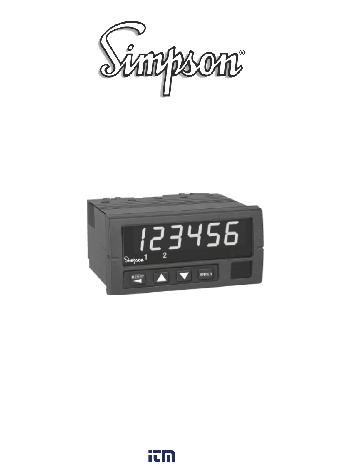
Digital Preset Totalizer & Batch Counter
Operation Manual
www. .com
[email protected]1.800.561.8187
Page 2

About this Manual
To the best of our knowledge and at the time written, the information contained in this
document is technically correct and the procedures accurate and adequate to operate this
instrument in compliance with its original advertised specications.
Notes and Safety Information
This Instruction Manual contains warning headings that alert the user to check for hazardous
conditions. These appear throughout this manual where applicable, and are dened below.
To ensure the safety of operating performance of this instrument, these instructions must be
adhered to.
Warning, refer to accompanying documents.
Attention, consulter les documents d’accompagnement.
Caution, risk of electric shock.
Attention, risque de choc électrique.
Warranty and Returns
SIMPSON ELECTRIC COMPANY warrants each instrument and other articles manufactured
by it to be free from defects in material and workmanship under normal use and service, its
obligation under this warranty being limited to making good at its factory or other article of
equipment which shall within one (1) year after delivery of such instrument or other article of
equipment to the original purchaser be returned intact to it, or to one of its authorized service
centers, with transportation charges prepaid, and which its examination shall disclose to its
satisfaction to have been thus defective; this warranty being expressly in lieu of all other warranties expressed or implied and of all other obligations or liabilities on its part, and SIMPSON
ELECTRIC COMPANY neither assumes nor authorizes any other persons to assume for it any
other liability in connection with the sales of its products.
This warranty shall not apply to any instrument or other article of equipment which shall have
been repaired or altered outside the SIMPSON ELECTRIC COMPANY factory or authorized
service centers, nor which has been subject to misuse, negligence or accident, incorrect wiring
by others, or installation or use not in accord with instructions furnished by the manufacturer.
Under the normal eld usage there is no need to remove the front bezel of this product. The
front bezel of this product should only be removed by a qualied technician.
1
www. .com
[email protected]1.800.561.8187
Page 3

Contents
1 Product Description. . . . . . . . . . . . . . . . . . . . . . . . . . . . . . . . . . . . . . . . . . . . . . . . . .3
1.1 General Description. . . . . . . . . . . . . . . . . . . . . . . . . . . . . . . . . . . . . . . . . . . . . . . 3
1.2 Part Number Identification. . . . . . . . . . . . . . . . . . . . . . . . . . . . . . . . . . . . . . . . . .3
1.3 Option Module Summary. . . . . . . . . . . . . . . . . . . . . . . . . . . . . . . . . . . . . . . . . . .4
2 Hardware Setup. . . . . . . . . . . . . . . . . . . . . . . . . . . . . . . . . . . . . . . . . . . . . . . . . . . . .5
2.1 Panel Installation. . . . . . . . . . . . . . . . . . . . . . . . . . . . . . . . . . . . . . . . . . . . . . . . . 5
2.2 Removing / Installing Option Modules. . . . . . . . . . . . . . . . . . . . . . . . . . . . . . . . 6
2.3 120/240 VAC Power Module. . . . . . . . . . . . . . . . . . . . . . . . . . . . . . . . . . . . . . . 7
2.4 Standard Input Module. . . . . . . . . . . . . . . . . . . . . . . . . . . . . . . . . . . . . . . . . . . . .7
2.5 Quadrature Input Module. . . . . . . . . . . . . . . . . . . . . . . . . . . . . . . . . . . . . . . . . . .9
2.6 Excitation Module. . . . . . . . . . . . . . . . . . . . . . . . . . . . . . . . . . . . . . . . . . . . . . . 12
2.7 Single and Dual Relay Modules. . . . . . . . . . . . . . . . . . . . . . . . . . . . . . . . . . . . .13
3 Display & Keypad Controls. . . . . . . . . . . . . . . . . . . . . . . . . . . . . . . . . . . . . . . . . . .14
3.1 Display. . . . . . . . . . . . . . . . . . . . . . . . . . . . . . . . . . . . . . . . . . . . . . . . . . . . . . . . 14
3.2 Display Error Messages. . . . . . . . . . . . . . . . . . . . . . . . . . . . . . . . . . . . . . . . . . . 15
3.3 What the Keys Do in Display Mode. . . . . . . . . . . . . . . . . . . . . . . . . . . . . . . . . 15
3.4 What the Keys Do in the Programming Mode. . . . . . . . . . . . . . . . . . . . . . . . . .16
3.5 Special Start-Up Modes. . . . . . . . . . . . . . . . . . . . . . . . . . . . . . . . . . . . . . . . . . . 17
4 Counter Operations and Parameters. . . . . . . . . . . . . . . . . . . . . . . . . . . . . . . . . . . . 18
4.1 Password and Security Controls. . . . . . . . . . . . . . . . . . . . . . . . . . . . . . . . . . . . 18
4.2 A/B Channel Options. . . . . . . . . . . . . . . . . . . . . . . . . . . . . . . . . . . . . . . . . . . . . 19
4.3 Count 1 Scaling and Display. . . . . . . . . . . . . . . . . . . . . . . . . . . . . . . . . . . . . . . 20
4.4 Count 2 (Batch) Scaling and Display. . . . . . . . . . . . . . . . . . . . . . . . . . . . . . . . . 21
4.5 Output Control Modes. . . . . . . . . . . . . . . . . . . . . . . . . . . . . . . . . . . . . . . . . . . . 23
4.6 Set Point Parameters. . . . . . . . . . . . . . . . . . . . . . . . . . . . . . . . . . . . . . . . . . . . . .24
4.7 Auto Reset Operations. . . . . . . . . . . . . . . . . . . . . . . . . . . . . . . . . . . . . . . . . . . . 25
4.8 Miscellaneous Controls. . . . . . . . . . . . . . . . . . . . . . . . . . . . . . . . . . . . . . . . . . . 26
Appendix A: Technical Specifications. . . . . . . . . . . . . . . . . . . . . . . . . . . . . . . . . . . .27
A.1 Functional Specifications. . . . . . . . . . . . . . . . . . . . . . . . . . . . . . . . . . . . . . . . . . 27
A.2 Electrical, Environmental and Mechanical Specifications. . . . . . . . . . . . . . . . .28
Appendix B: Programming Quick Reference. . . . . . . . . . . . . . . . . . . . . . . . . . . . . . .30
2
www. .com
[email protected]1.800.561.8187
Page 4
1 Product Description
1.1 General Description
The S662 preset totalizer & batch counter fits a 1/8 DIN standard cutout and is perfect for
tight spaces, extending only 3.24” (82mm) behind the panel. The unit is UL listed. The
unit is for indoor use at altitudes up to 2000m, temperatures between 0° and 40°C, and
installation category III, pollution degree 2.
The counter is powered from 120 or 220 VAC. The nonvolatile EEPROM retains all programming and count information when power is removed or interrupted.
Display scaling, preset values and all menu functions are easily programmed from the
front panel, following easy-to-use word prompts. Front panel reset disable and password
lockout protection features guard against unauthorized or accidental changes.
The counter accepts count rates up to 20 kHz and pulses from different types of sensors,
including Quadrature, CMOS or TTL circuits and PNP or NPN devices.
The optional field-replaceable single/dual relay, DC module enhances the counter from a
passive display device to an integral control element for your application. Outputs may
be controlled by Count or Batch values with independent reset operations. The counter
has latching, boundary or timed 0.01 to 599.99 seconds) output modes. An optional 12
VDC (100mA) excitation output module can provide power for external sensors.
1.2 Part Number Identification
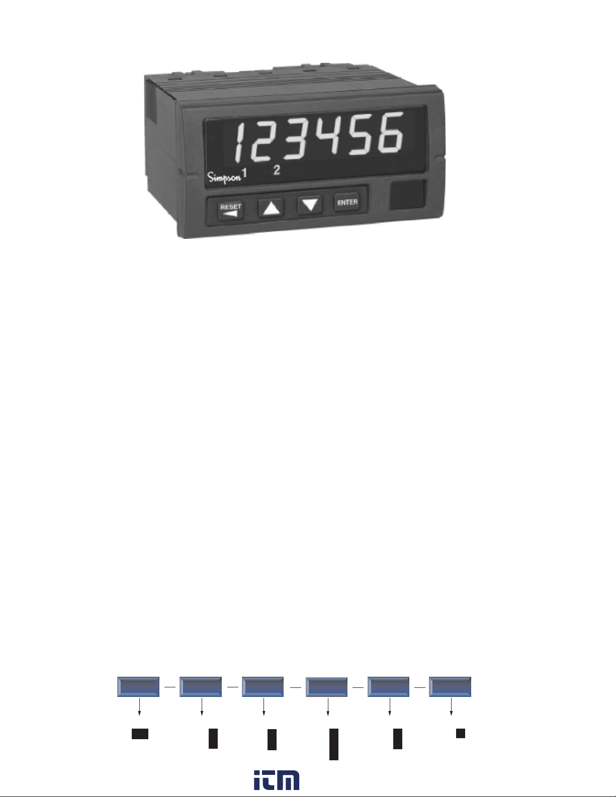
The following matrix indicates the configuration of your S662 counter.
Basic Unit
S662
Power Supply
120 VAC
240 VAC
1
2
www. .com
Input
Standard
Quadrature
Output
1
2
One relay
Two Relays
None
0
1
2
Excitation
None
12VDC
0
1
Other
None
3
[email protected]1.800.561.8187
0
Page 5
1.3 Option Module Summary
1
Input Excitation Power
2
4
Supply
5
Output
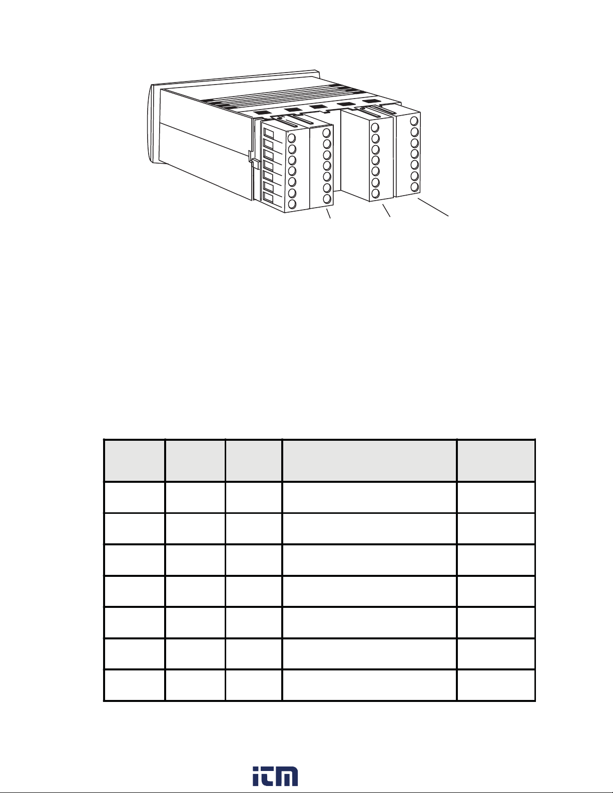
Figure 1. Option Module Slots (Rear View)
The S662 is modular product which uses field configuring slide-in modules. The modules slide easily into the rear of the counter.
Table 1 describes available option modules for the S662.
Table 1. Option Module Summary
Module
slot
1 Input Standard Input Module
Type P/N Description
See
Section
2.4
1 Input Quadrature Input Module
2 Ext 45064 12 VDC Excitation Module
4 Power 120 VAC Power Module
4 Power 240 VAC Power Module
5 Output 45062 Dual Relay Module
5 Output 45063 Single Relay Module
4
www. .com
[email protected]1.800.561.8187
2.5
2.6
2.3
2.3
2.7
2.7
Page 6
2 Hardware Setup
2.1 Panel Installation
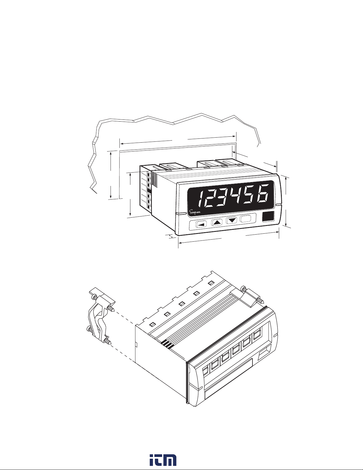
The S662 1/8 DIN counter requires a standard 1/8 DIN panel cutout of 1.77” (45mm)
high by 3.62” (92mm) wide. To install the counter into a panel cutout, remove the clips
from the side of the counter. Slide the counter through your panel cutout, then slide the
mounting clips back on. Press evenly to ensure a proper fit.
3.62"
92mm
3.24"
82mm
1.77"
45mm
1.74"
44mm
2.04"
51.8mm
ENTER
3.93"
.52"
13.2 mm
%
RESET
99.8 mm
Figure 2. Counter and Panel Cut-Out Dimensions
Figure 3. Panel Mounting Clips
5
www. .com
[email protected]1.800.561.8187
Page 7
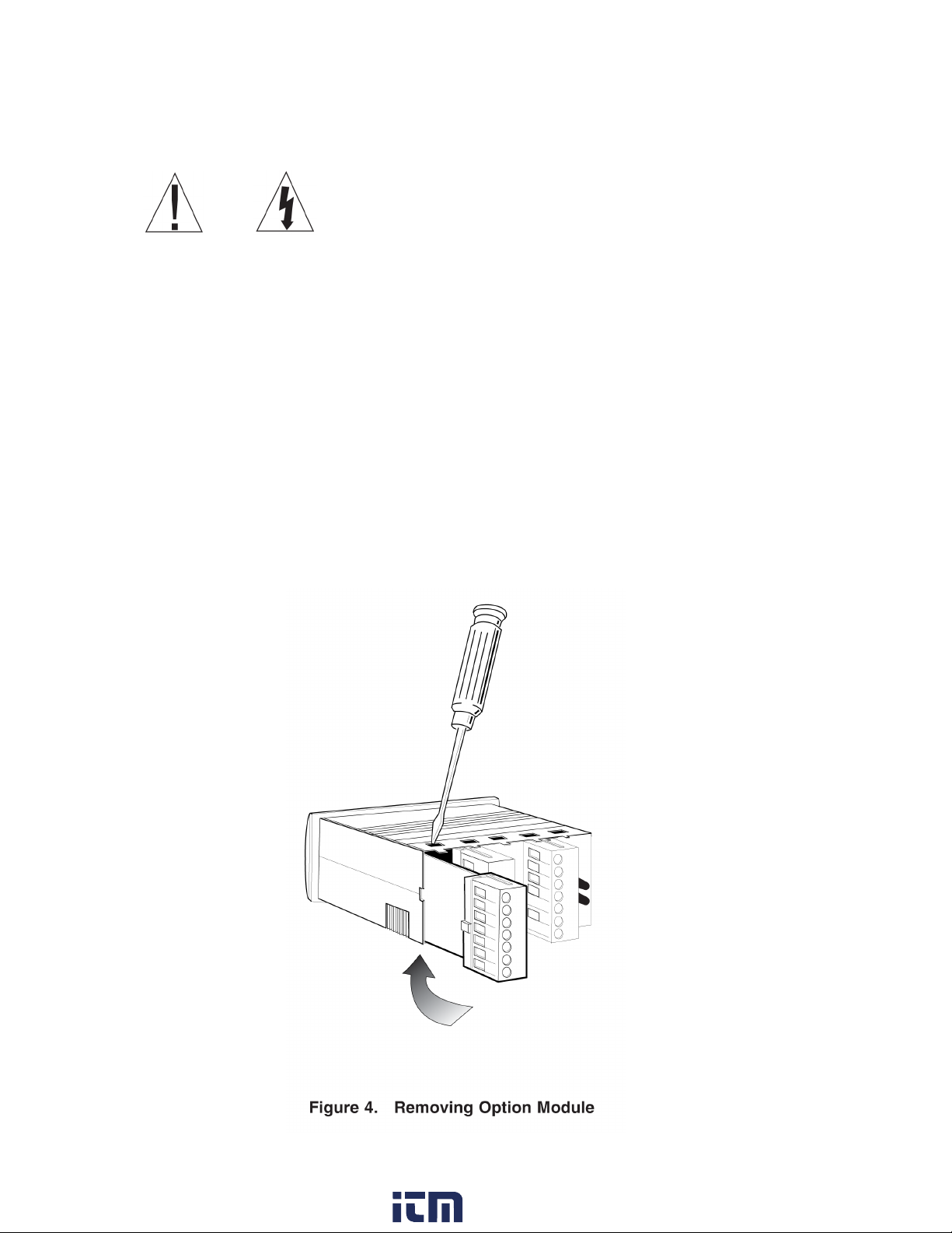
2.2 Removing / Installing Option Modules
Shut power off before removing or installing any option modules
Couper le courant avant de retirer ou d’installer des modules optionnels
1. Remove module from case by inserting a screwdriver into tab slot opening at top of input
module. Apply pressure to release module from case. Repeat procedure for tab located on
underside of module and then slide module away from the case.
2. Refer to appropriate sections to congure switches or jumpers for proper operation.
Table 1 can be used to identify modules and their associated detail paragraph.
3. Install module by carefully aligning module edges with slots in case and pressing forward
until tabs (on top and bottom) engage.
6
www. .com
[email protected]1.800.561.8187
Page 8
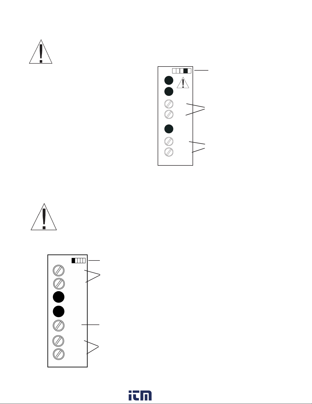
2.3 120/240 VAC Power Module
Remove power before wiring option modules.
Coupez l’alimentation avant de raccorder les modules optionnels.
The AC power module allows the S662 to be
operated from standard 50/60 Hz line power.
The power module will be congured as 120
VAC or 240 VAC per markings on the back
panel. Ensure the input rating of the supply
matches your line voltage. The power supply
module has provisions for a hard-wire Primary
(Count 1) Reset. This control can be a switch,
relay contact or solid state device. Actuation
is immediate upon an active Low for at least
2.5ms to this terminal. The reset circuit is
independent of the power circuit.
Denotes modules position 4 at rear
of counter
~
~
VAC
VAC
RESET
COMMON
POWER
Power Supply 120 VAC or 240 VAC
power connection
Remote Reset
Active low 0.2V performs primary
reset
Figure 5. AC Power Module
NOTE: A fusible link is not provided on this module.
A ½ Amp Time Delay fuse, Bussman MDL ½, or similar is required.
Never connect AC mains (hot or neutral) to the Reset or Common terminals!
Ne jamais brancher sur secteur (chaudes ou neutres) pour la réinitialisation
ou terminaux communs!
2.4 Standard Input Module
Denotes module position 1 at rear of counter
A INPUT
COMMON
USER
INPUT
Primary Input
Connect the input signal to A INPUT and COMMON
Count 2 Reset
Active low resets Batch count and alarms
B INPUT
COMMON
IINPUT
Secondary Input
Direction Control or count pulse input
Figure 6. Standard Input Module
7
www. .com
[email protected]1.800.561.8187
Page 9
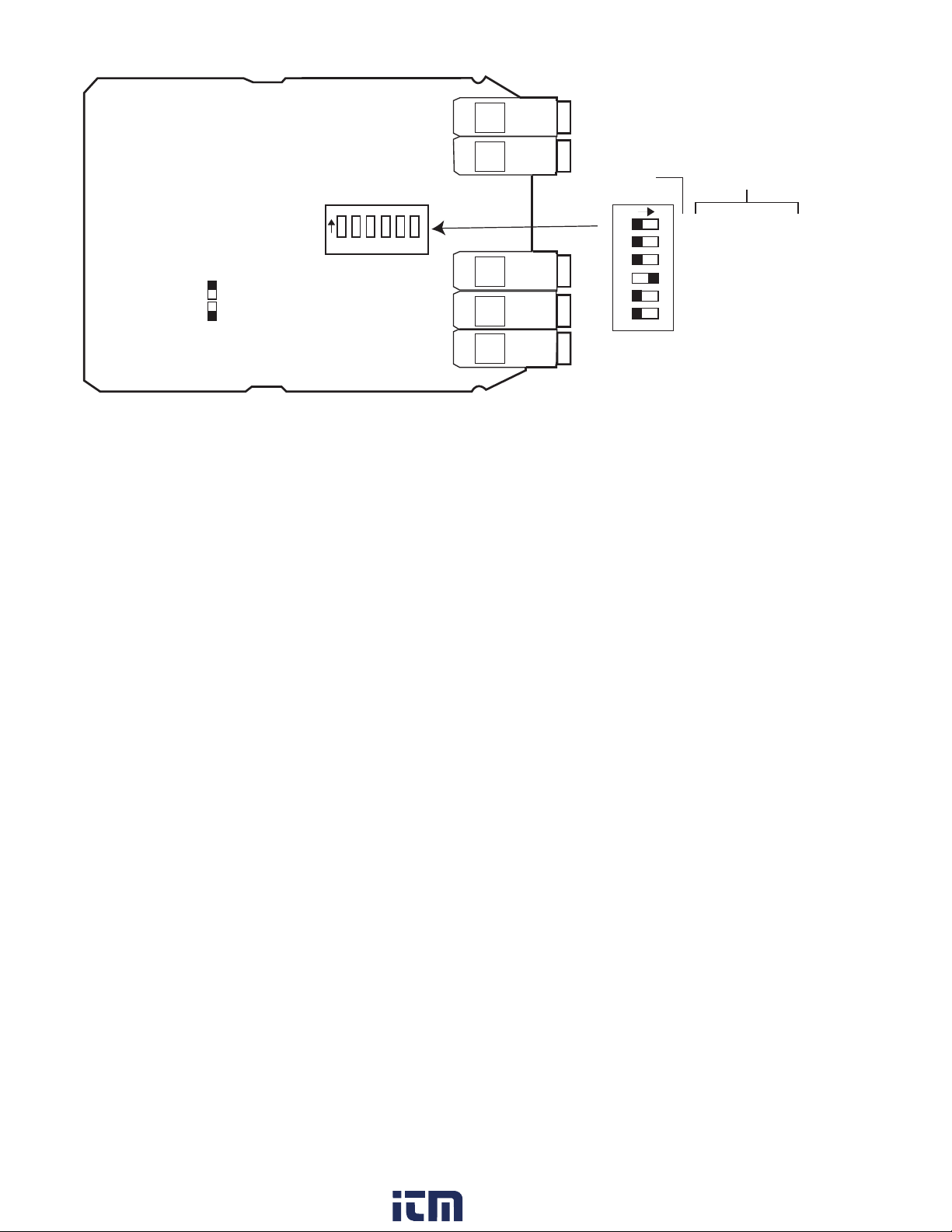
DIP Switch
(Shown for TTL Factory Settings)
FUNCTION
B Bias Off=Hi On=Lo
B Freq Off=Hi On=Lo
B Off= Sink On= Source
A Bias Off=Hi On=Lo
A Freq Off=Hi On=Lo
A Off= Sink On= Source
Dipswitch Legend
CHANNEL
1 2 3 4 5 6
1 2 3 4 5 6
= ON
= OFF
Note: Refer to specifications
for DIP switch function
electrical characteristics
Figure 7. Standard Input Module Default Settings
DIP switch SW1, figure 7, is used to set up the counter to conform to the electrical characteristics of the sensor or signal being detected. Switch positions 1-3 configure channel
B, while switches 4-6 configure channel A. These switches select bias (threshold voltages), low pass filter (enable/disable) and sensor type (Sink or Source).
Refer to the documentation that accompanied the sensor for related information. The
sensor can most likely be matched to one of the typical switch settings shown in figure 8
and figure 8a.
Note: The input boards are designed so that selecting sourcing or sinking is based
on the type of sensor that is being used. If a PNP (sinking) sensor is being used, set
the input board for sinking also (switches 3 and 6 = OFF).
If channel B is not used, default settings for switch positions 1 through 3 should be selected. Default settings are provided in Table 2.
The input module also provides for a user input signal. On the S662, this input serves
as the secondary channel (Batch) hard-wired reset. This may be used to reset the batch
count while preserving the primary count.
The S662 can accept inputs from many different sensors. The A and B channels may be
configured independently as shown in Table 2. Figures 8 and 8a have examples of some
typical sensors and the wiring connections that would be used.
8
www. .com
[email protected]1.800.561.8187
Page 10
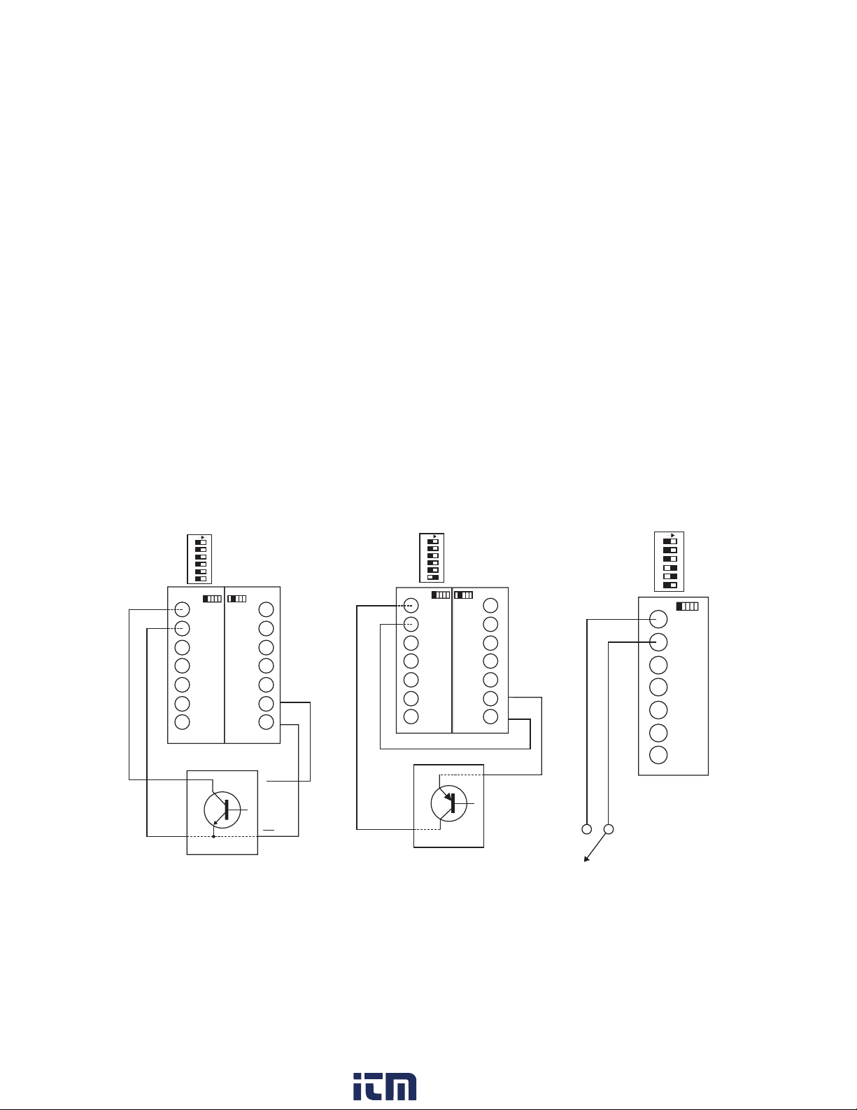
Table 2. Standard Input Module DIP Switch Settings(* = Factory Default Setting)
+
1 B Channel Bias: OFF = Hi* VLT = 5.0 V VUT = 7.0V (+/- 10%)
ON = Low VLT = 1.6 V VUT = 3.6V (+/- 10%)
2 B Channel Frequency: OFF = Hi* (low pass filter disabled)
ON = Lo (low pass filter enabled)
3 B Channel Sensor: OFF = Sinking* (internal pull-up enabled)
ON = Source (internal pull-down enabled)
4 A Channel Bias: OFF = Hi VLT = 5.0 V VUT = 7.0V (+/- 10%)
ON = Low* VLT = 1.6 V VUT = 3.6V (+/-10%)
5 A Channel Frequency: OFF = Hi* (low pass filter disabled)
ON = Lo (low pass filter enabled)
6 A Channel Sensor Type: OFF = Sinking* (internal pull-up enabled)
ON = Source (internal pull-down enabled)
ON
1 2 3 4 5 6
LOW BIAS
LOW FREQUENCY
SOURCING
A INPUT
COMMON
USER INPUT
B INPUT
COMMON
INPUT
HIGH FREQUENCY
ON
1 2 3 4 5 6
LOW BIAS
LOW FREQUENCY
SOURCING
A INPUT
COMMON
USER
INPUT
B INPUT
ISO+12V
ISOCOM
COMMON
EXCITATION
INPUT
PNP SENSOR
__
---
HIGH FREQUENCY
+
_
HIGH BIAS
SINKING
DRY CONTACT
HIGH BIAS
SINKING
OUTPUT
COMMON
ON
1 2 3 4 5 6
LOW BIAS
LOW FREQUENCY
SOURCING
A INPUT
COMMON
USER
INPUT
B INPUT
ISO+12V
ISOCOM
COMMON
INPUT
EXCITATION
NPN SENSOR
HIGH BIAS
__
---
HIGH FREQUENCY
+
_
SINKING
Figure 8. Sensor Connection Examples Figure 8a Sensor Input Example
2.5 Quadrature Input Module
The Quadrature / Universal Input Module has two operational modes: Quadrature mode
and Standard mode. Quadrature mode is selected by positioning JP1 and JP2 on pins 1
and 2. Standard mode is selected by placing JP1 and JP2 on pins 2 and 3 (see Figure 10
for details). The Quadrature mode supports a wide range of encoders including the Simpson SE series.
9
www. .com
[email protected]1.800.561.8187
Page 11
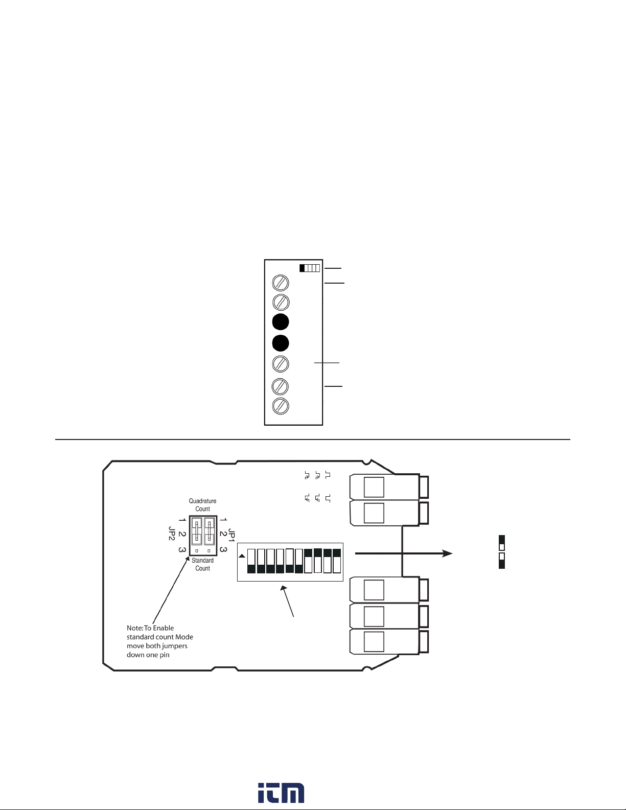
While in Standard mode, this module works similarly to the Standard Input module, with the
added capability to selectively invert A, B, and User input signals.
The Input module also provides for a User input signal. On the S662, this input serves as the
secondary channel (Batch) hard-wired reset. This may be used, for example, to reset the
batch count while preserving the primary count.
In both modes, the state of the User input signal can be selected as active high or active
low. DIP switch SW1 congures the counter to match the specications of the accompanying
sensor. When shipped from the factory, the counter is set for X1 quadrature, as shown in
Figure 10 and Table 3: Switch settings for SW1 positions 1 through 3.
Default settings are provided in Table 3.
Denotes module position 1 at rear of counter
A INPUT
COMMON
Figure 9.
Quadrature / Universal Input Module
Primary Input or Quadrature A
NOTE:
If B channel is not going to be used, use the default
IINPUT
B Bias Off = Hi On = Lo
B Freq Off = Hi On = Lo
B Off = Sink On = Source
A Bias Off = Hi On = Lo
1
456
3
2
Dip Switch:
Shown in
Quadrature Mode
(Factory Default)
USER
INPUT
B INPUT
COMMON
A Freq Off = Hi On = Lo
A Off = Sink On = Source
B Edge Off = On =
A Edge Off = On =
7
SW1
Count 2 Reset Active low Reset Batch count and alarms
Secondary Input or Quadrature B
User pol Off = On =
Quadr Off = X4 On = X1
Dip Switch
Legend
9810
= ON
= OFF
Figure 10. Quadrature Input Module Default Settings
10
www. .com
[email protected]1.800.561.8187
Page 12

Table 3. Quadrature Module DIP Switch and Jumper Settings
JP1/2: Count Mode Selector
Jumpered 1-2 = Quadrature mode
Jumpered 2-3 = Standard counter mode
SW1: 10 Position DIP Switch
* = Factory Default setting
1 B Channel Bias: OFF = Hi* VLT = 5.0V VUT = 7.0V (+/- 10%)
ON = Low VLT = 1.6V VUT = 3.6V (+/- 10%)
2 B Channel Frequency: OFF = Hi* (low pass filter disabled)
ON = Low (low pass filter enabled)
3 B Channel Sensor: OFF = Sinking* (internal pull-up enabled)
ON = Source (internal pull-down enabled)
4 A Channel Bias: OFF = Hi* VLT = 5.0 V VUT = 7.0V (+/- 10%)
ON = Low VLT = 1.6 V VUT = 3.6V (+/- 10%)
5 A Channel Frequency: OFF = Hi* (low pass filter disabled)
ON = Lo (low pass filter enabled)
6 A Channel Sensor Type: OFF = Sinking* (internal pull-up enabled)
ON = Source (internal pull-down enabled)
7 B Channel Count Edge: OFF = Rising (standard count mode only)
ON = Falling*
8 A Channel Count Edge: OFF = Rising (standard count mode only)
ON = Falling*
9 User Input Polarity: OFF = High/open circuit = Inhibit Count
ON* = Low/closed circuit = Inhibit Count
10 Quadrature Mode: OFF = X4 (quadrature mode only)
ON = X1*
11
www. .com
[email protected]1.800.561.8187
Page 13
2.6 Excitation Module
QUADRATURE
ENCODER
PHASE A-WHITE
PHASE B-GREEN
+
COMMON
(BLACK)
POSITIVE-RED
A INPUT
COMMON
USER
INPUT
B INPUT
COMMON
INPUT
QUADRATURE
INPUT CARD
ISO+12V
ISOCOM
EXCITATION
EXCITATION
CARD
+
__
---
_
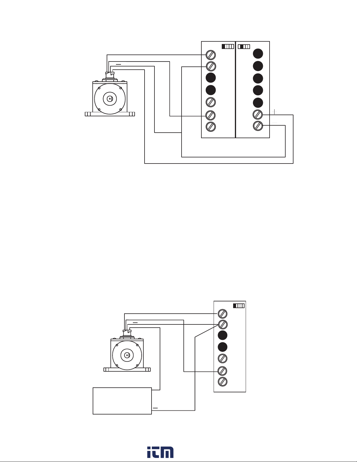
Figure 11. Wiring Encoder w/ Excitation Supply
12 VDC Excitation Module
The Excitation Module can supply 12 VDC at up to 100 mA for external sensors or encoders. This excitation is isolated from the counter internal logic supply. When using
sensors or encoders that do not have a signal return or imply a signal return that is in
common with the supply voltage, a common attachment that ties the excitation supply
to the logic input common may be required. Examples of this appear in figures 8, 8a, 11
and 12.
DENOTES MODULE POSTION 1
AT REAR OF COUNTER
MODEL S.E.
QUADRATURE
ENCODER
CHANNEL A-WHITE
CHANNEL B-GREEN
POSITIVE (RED)
EXTERNAL
POWER
SUPPLY
+
+
COMMON
(BLACK)
A INPUT
COMMON
USER
INPUT
B INPUT
COMMON
INPUT
QUADRATURE
INPUT CARD
Figure 12. Wiring Encoder with External Supply
12
www. .com
[email protected]1.800.561.8187
Page 14
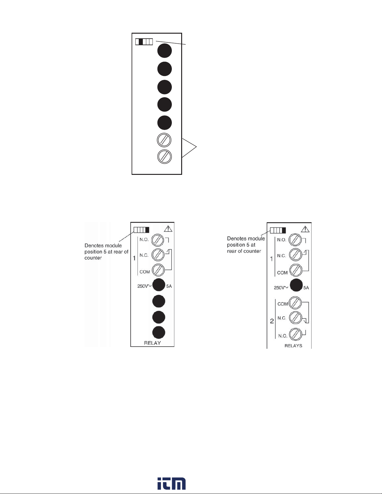
Denotes module
position 2 at rear of
counter
ISO+12V
+
__
---
ISOCOM
EXCITATION
_
Figure 12. Excitation Module
2.7 Single and Dual Relay Modules
12 VDC, 100 mA max
Figure 14. Single Relay Figure 15. Dual Relay
The Single and Dual Relay modules can activate circuit loads of up to 5 amps at 250
VAC. A Form C configuration allows use of normally-open (NO) and normally-closed
(NC) circuit action. Only the output 1 channel is implemented in the single relay module.
13
www. .com
[email protected]1.800.561.8187
Page 15
3 Display & Keypad Controls
3.1 Display
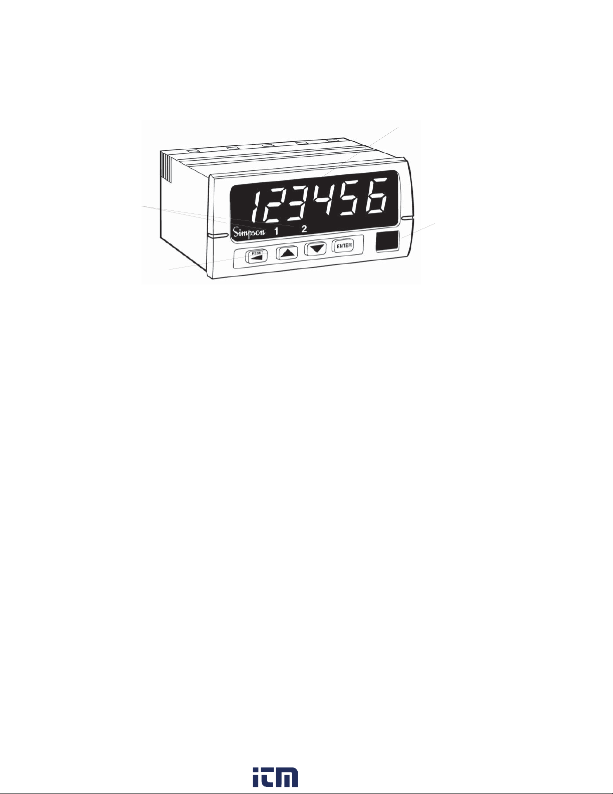
Output Status
Indicators
Numeric & Message Display
Units Window
4 Button Keypad
• 6-Digit 0.56” high red LED Display.
• 2 Output Status Indicators; “1” and “2.”
• Units Window for supplied label or legend.
• 4-Button Keypad with tactile response.
Figure 16. Display and Keypad Layout
14
www. .com
[email protected]1.800.561.8187
Page 16
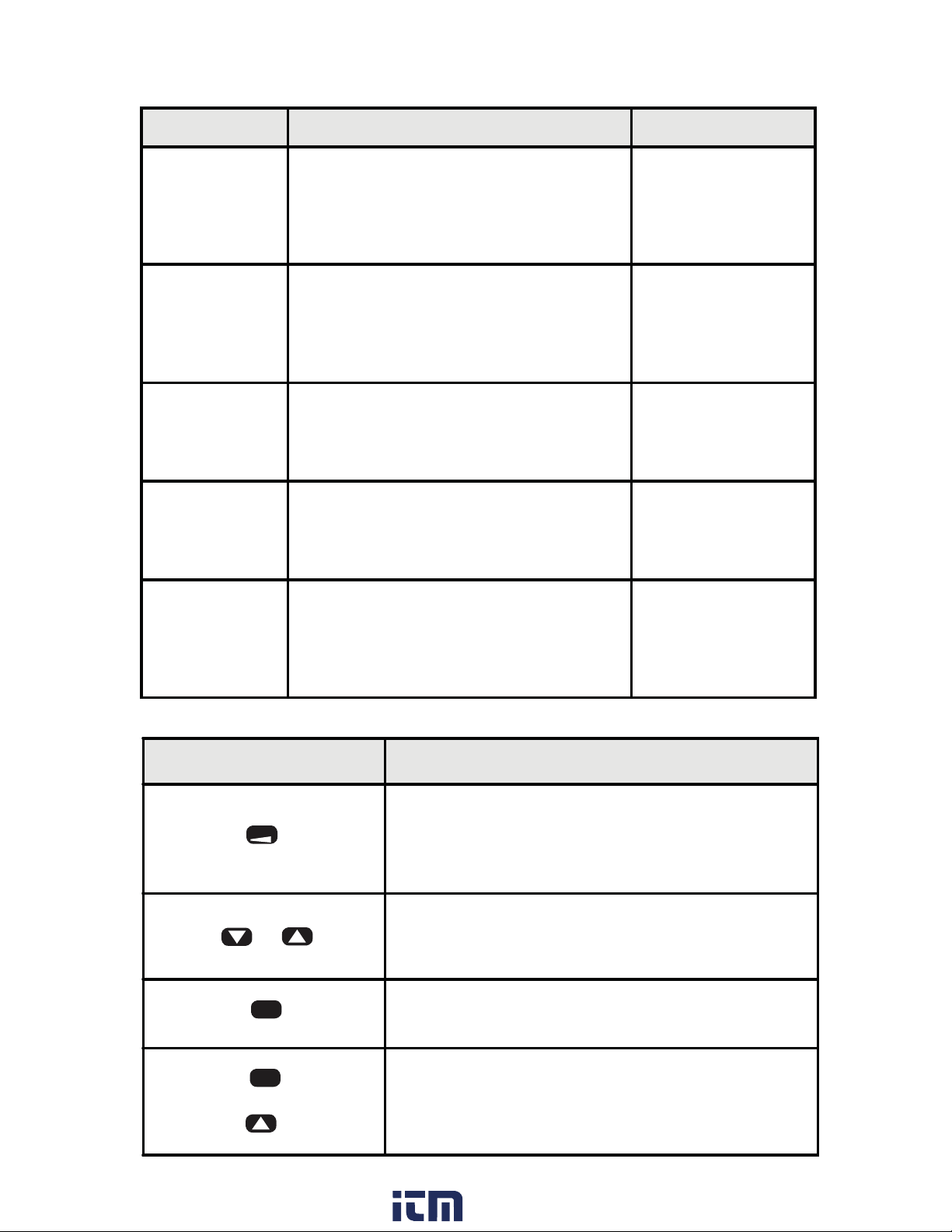
3.2 Display Error Messages
Table 4. Display Error Messages
Display Description Action Required
PAdErr
The Keypad is disabled or a key is stuck in
the ON position
Cycle power to the
counter, if the error
remains, return
counter to factory for
repair.
999999 or
-99999
(Flashing)
E1
(Outputs
deactivate, count
stops)
E2
(Outputs
deactivate, count
stops)
E3
(Outputs
deactivate, count
stops)
The displayed count is too large for the
counter to display. Since the internal count
buffer is much larger than the display, the
counter will maintain accurate count and
control well beyond the display value.
Raw Count Overflow: The number of count
pulses has exceeded the counter’s maximum
internal value (2,147,483,648 or
-2,147,483,648)
Math Overflow: A large scale factor in
combination with large raw count has
exceeded the counter's maximum internal
value (+2,147,483,648 or -2,147,483,648)
Watchdog Fault: The counter did not
experience an orderly power-down. This can
happen by exceeding the maximum
allowable count speed for a sustained period
of time.
3.3 What the Keys Do in Display Mode
Reset Counter
Reset Counter
Reset Counter
Reset Counter
Key Keypad behavior
RESET
S or T
ENTER
Hold and
ENTER
Press S
If current Display Value is Count 1, resets Count
1 to RstP 1 parameter. If current Display value is
Count 2, resets Count 2 to RstP 2 parameter. This
action may be disabled (see section 4.7).
Allows quick access to all the set points and
RstPos (Reset Position). This feature can be
disabled by using a password (see section 4.1).
Select current Display Value (Count 1 or Count 2).
Access the Programming Menu.
15
www. .com
[email protected]1.800.561.8187
Page 17
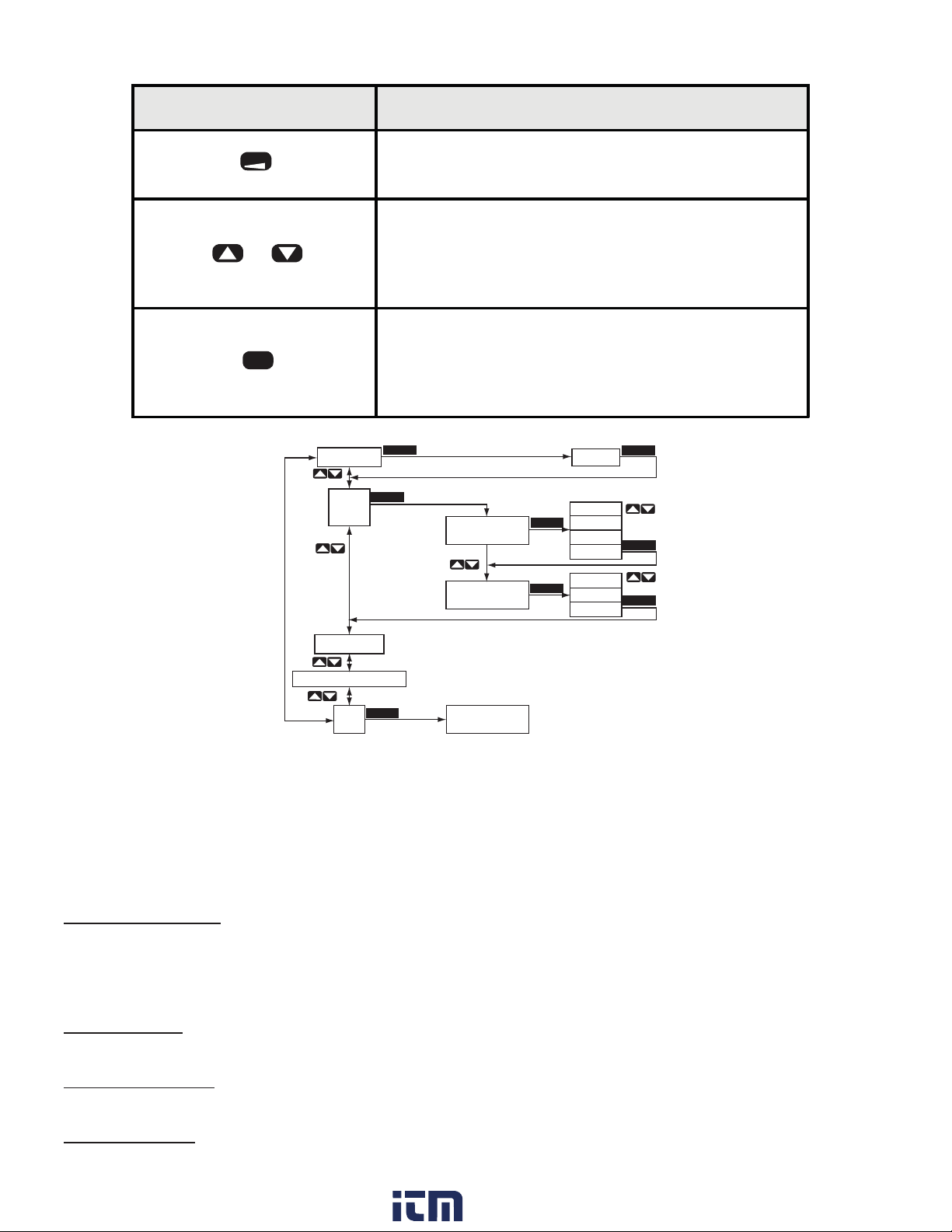
3.4 What the Keys Do in the Programming Mode
Key Keypad behavior
RESET
S orT
ENTER
Press and hold for four seconds to exit the
programming mode.
The up and down keys navigate through the
available menu functions. The menu ‘wraps
around’ when the bottom or top of the menu is
reached.
1) Enter the current menu or parameter to
view/edit.
2) Write the change to the counter memory and
move to the next function.
Setup Menu Function Menu Option Menu
CHPASS 000
INPUT
SETUP
ENTER
ENTER
A CHAN UP
B CHAN DOWN
ENTER
ENTER
000
up
down
quad
rquad
dir
up
down
ENTER
ENTER
ENTER
COUNT SETUP
other setup menus
END
ENTER
Return to
Display Mode
Figure 17. Programming Menu Structure
In the Programming Mode, the S662 will return to Display Mode automatically if a key
is not pressed within 120 seconds (2 minutes). The menu is comprised of three levels:
Setup Menu, Function View and Option Edit. Figure 17 illustrates the three levels of the
menu system.
Password Entry Entry (Pass) and changing of the password (Chpass) are similar to edit-
ing a numerical parameter. See Numerical Value below. If the password has been set to a value other than “000,” entry of the proper password is required to access the remainder of the menu.
Setup Menu At the first level of the menu, the keys navigate up or down through the
available Menu Categories.
Function Menu The second level of the menu contains the function or software param-
eters that need to be configured for the counter to operate properly.
Option Menu Contains either Choice Lists or Numerical Values for configuring the
functions of the counter.
16
www. .com
[email protected]1.800.561.8187
Page 18
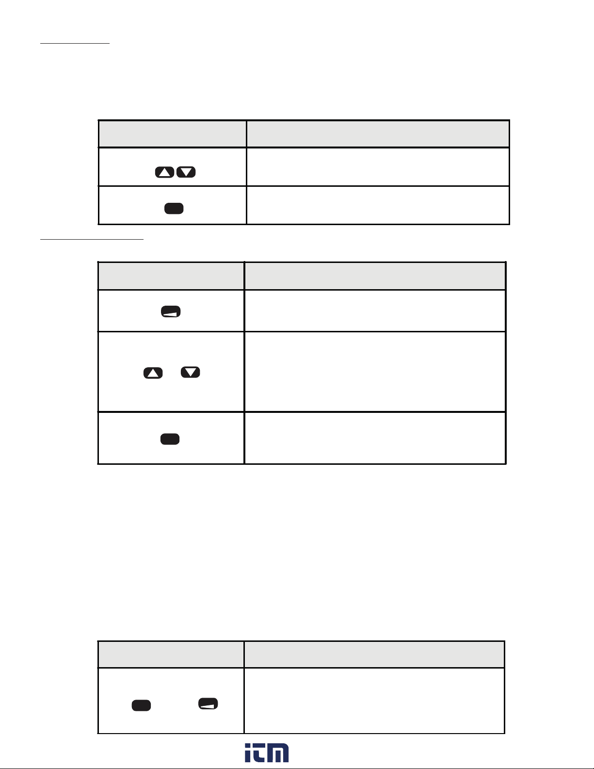
Choice List A choice list allows selection from a fixed number of options. A Choice
List is found in the Options section of the menu. The list is made up
of the available options for the function that is being edited. Example:
Menu is Input Setup Menu, the Function is A Channel, the Choice List is
up, down, quad, and squad. (See Table 6)
Key Keypad behavior
The up and down keys scroll through the
ST
available choices in the Choice list.
ENTER
Saves the current choice as new parameter
setting and steps to next parameter or category.
Numerical Value A numerical entry allows the changing of set point values, scale
values, etc.
Key Keypad behavior
RESET
S or T
ENTER
Selects the next digit to the left of the current
flashing digit for editing.
The up and down keys increment or decrement
the flashing digit. Some parameters support
negative numbers. In these cases, the most
significant digit can be made negative by
incrementing it between "9" and "0."
Saves the values as the new setting for the
function in memory and advances to the next
function of the menu automatically.
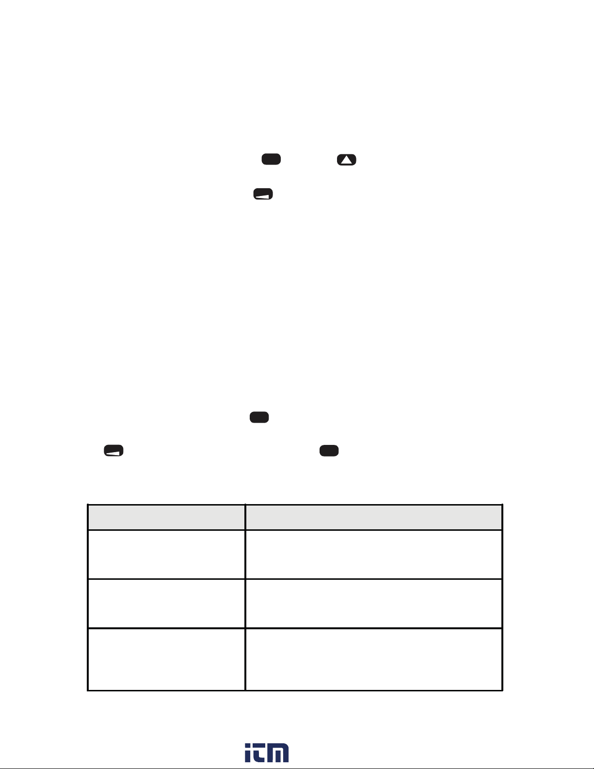
3.5 Special Start-Up Modes
There are two start-up modes for the S662 counter. The default start-up mode will be
used every time the counter is powered up by the user. There is one alternate start-up
mode that will allow the operator to return the counter software functions to factory default settings.
The alternate start-up modes can only be accessed by pressing and holding certain keys
during the power up sequence.
• Press and hold both keys on the face of the counter
• Apply power while holding keys
Key Keypad behavior
Returns parameters to factory defaults. Resets
ENTER
and
RESET
www. .com
password to 000, and all user scaling, operation
modes and set points to factory defaults. Display
will show freset.
17
[email protected]1.800.561.8187
Page 19
4 Programming Operations and Parameters
This section details the initial programming options of the S662, presuming all defaults
are in place.
If you are already familiar with the S662 programming, see Appendix B for the Programming Quick Reference Guide.
To enter the Programming Mode, hold and press p .
To return to the Display Mode, press and hold for four seconds when counter is not in
ENTER
RESET
an option menu.
4.1 Password and Security Controls
The security feature helps prevent accidental changes to counter settings.
The password value determines the counter’s security level, as shown in Table 5.
If you have forgotten the password, see section 3.5; Special Start-Up Modes.
1) After entering the Programming Mode, the first field is Password.
a) If no password has been assigned, the counter will flash between chpass, for
“Change Password” and the default value, 000.
b) To change the password, press when the display shows 000. Use the arrow keys
to change the flashing digit to the desired number.
c) Press to advance to the next digit. Press to accept the password to counter
RESET
ENTER
ENTER
memory and press it again to advance to the next parameter, Input Setup.
Table 5. Password Values
Password Value Level of Security
No Security - Default setting
000
001 - 099
100 - 999
Allows full access to the Programming Menu and
Quick Access to set points is enabled.
Fully secure
The Programming Menu is secured by password
and Quick Access to set points is disabled.
Quick Access Only
Programming Menu is secured by password,
Quick Access to set points via up and down keys
enabled.
18
www. .com
[email protected]1.800.561.8187
Page 20
2) If a password is already in the counter, the display will flash between pass, for “Enter Password,” and the default value, 000.
a) When the display shows 000, press . Use the arrow keys to change the flashing
digit to the desired number. Press to advance to the next digit.
b) Press to enter the password as shown. If an incorrect password is entered, access
ENTER
ENTER
RESET
denied will flash on the display. Press an arrow key to return to the pass display.
c) After entering the correct password, the counter will return to chpass. Press to
ENTER
change password, or press the key to continue to the Input Setup menu category.
4.2 A/B Channel Options (Input Setup)
The next category in the Programming Mode is the “Input Setup.” Here you can adjust
the A and B channels to the appropriate count modes.
The A channel input may be selected as an Up, Down, Quadrature or Reverse Quadrature* input.
As an Up channel, pulses applied to the A input are added to the display. In Down mode,
subtraction occurs. Note that when using Quadrature inputs, appropriate hardware (jumper) settings may be needed. The Reverse Quadrature input allows the user to reverse the
count direction of the encoder in software instead of having to rewire/remount the encoder.
Table 6. Channel A Selection
A CHAN Direction B CHAN
UP Up User defined
DOWN Down User defined
QUAD Up Not Available
R QUAD Down Not Available
1) To set the A Channel value:
a) When the display flashes input setup, press . The display will change to a chan.
b) Press again to proceed to the choice list. Scroll through up, down, quad, and r
ENTER
ENTER
quad using the arrow keys.
c) When the selection is complete, press to accept the selection to counter memory
ENTER
and proceed to the next parameter, Chan B Mode.
The B channel may be set as Up, Down or Direction. In the direction mode, the B channel is no longer a count source, but controls the count direction of the A channel input.
This state control works as an ‘exclusive-or’ with the channel A direction. Thus, if B
input is in the ‘Down’ state and A channel is set to Down, pulses at the A input will increment count.
19
www. .com
[email protected]1.800.561.8187
Page 21

Table 7. Count Behavior with B Channel Set as Direction Control
A Channel Setting State at B Input Resulting Count
UP UP UP
UP DOWN DOWN
DOWN UP DOWN
DOWN DOWN UP
When A channel has been set to either Quadrature or Reverse Quadrature settings, the B
channel internally behaves as a direction control.
2) To set the B channel:
a) In the Input Setup area, after entering the A Chan value, the display will flash be-
tween b chan and the counter’s default (dir).
b) When the display shows dir, press .
c) Use the arrow keys to change the value, then press to accept the selection and
ENTER
ENTER
proceed to the next menu category, Count Setup.
NOTE: The B channel will not show in the menu when Quadrature or Reverse
Quadrature has been selected for the A Channel input.
4.3 Count 1 Scaling and Display (Count 1 Setup)
Scale
The S662 counter allows for scaling of display values. Scaling allows the counter to display a more accurate number than its 6-digit capacity might otherwise allow.
Generally speaking, the smaller the scale value, the more accurate the count will be. The
S662 has four prescale values, 1.0 (default), 0.1, 0.01, and 0.001.
An example of this application is as follows:
A 600 pulse-per-revolution encoder is used to measure cable before it is cut to the proper
length. There is a wheel (one foot in circumference) attached to the encoder, in direct
contact with the cable. The user wants to see the counter display feet to 1/100’ accuracy
(to two decimal points).
With the default scale of 01.0000, one rotation of the wheel would be displayed on the
counter as 00.0016’. However, by using a prescale of 0.01, the resolution has been multiplied by 100, allowing the counter to display 0.16667, increasing the accuracy of the
counter and allowing more accurate cutting.
1) To access the user-defined scaling parameter, enter the Programming Mode, and
press q until the count 1 setup menu category is reached.
20
www. .com
[email protected]1.800.561.8187
Page 22

2) Press to continue to the Parameter Name scale1. The display will flash between
scale1 and the default value of 01.0000. When the display shows scale1, press
3) Use the arrow keys to enter the correct value of the flashing digit. Use the key to
advance to the next digit. Press when the correct scale is selected to accept value
ENTER
ENTER
RESET
ENTER
and proceed to the next parameter, DP 1.
To calculate the scaling parameter, use the following scale formula:
Display = Multiplier (Pulse x Prescale x Scale x Decimal Point)
If the scale value isn’t known, use the following formula:
SCALE =
DISPLAY X Dp
MULT. (PULSE X PRESCALE)
For the example we used, the scale value is:
1.00
SCALE =
= 0.1667
1 (600) X 0.01
Decimal Point Position
1) To set the Decimal Point position, enter the Programming Mode, and press q until
the count1 setup menu is reached.
2) Press to continue to the Parameter Name dp 1. The display will flash between
dp 1 and the default 000000. When the display shows 000000, press .
3) Use the arrow keys to scroll through the choices. Press when the correct decimal
ENTER
ENTER
ENTER
place is selected to accept value and proceed to the next menu category, Count 2
Setup.
4.4 Count 2 (Batch) Scaling and Display (Count 2 Setup)
Count 2 operation may be controlled in one of two ways: Dual mode and Batch Mode.
Dual Mode
In Dual Mode, the Count 2 is increased or decreased at the same time Count 1 is increased or decreased. The counter operates like two independent counters sharing the
same input signal. Each “counter” has independent scaling and reset controls.
Batch Mode
In Batch Mode, Count 2 is increased whenever an Auto Reset occurs on Count 1. The
Auto Reset parameters (see section 4.7) must be configured for the application.
The Count 2 display value is independent of the Count 1 display value. The secondary
“channel” in the S662 has its own scaling values and decimal position. The Scale 2 multiplier and Decimal Point 2 locations operate similar to that for Count 1. In addition, a
Count 2 Prescale is available. This allows a large accumulating raw count to be reduced
to a much smaller (display-able) number.
1) To set the Batch Mode, enter the Programming Mode, and press until the count2
setup menu is reached.
2) Press to continue to the Parameter Name mmode. The display will flash between mode and the default dual. When the display shows dual, press .
ENTER
21
ENTER
www. .com
[email protected]1.800.561.8187
Page 23

3) Use the arrow keys to scroll through the choices. Press when the correct batch
ENTER
mode is selected to accept value and proceed to the next menu category, Count 2
Prescale.
Prescale
The S662 counter allows for prescaling of display values. Prescaling allows the counter
to display a more accurate number than its 6-digit capacity might otherwise allow. Generally speaking, the smaller the scale value, the more accurate the count will be. The
S662 has four prescale values, 1.0 (default), 0.1, 0.01, and 0.001.
An example of this application is as follows:
A 600 pulse-per-revolution encoder is used to measure cable before it is cut to the proper
length. There is a wheel (one foot in circumference) attached to the encoder, in direct
contact with the cable. The user wants to see the counter display feet to 1/100’ accuracy
(to two decimal points).
With the default prescale of 1.0, one rotation of the wheel would be displayed on the
counter as 00.0016’. However, by using a prescale of 0.01, the resolution has been multiplied by 100, allowing the counter to display 0.16667, increasing the accuracy of the
counter and allowing more accurate cutting.
1) To access the prescale parameters, enter the Programming Mode, and press until
the count2 setup menu category is reached.
2) Press to continue to the Parameter Name prescl. The display will flash between
prescl and the default value of 1.0. When the display shows 1.0, press .
3) Use the arrow keys to scroll through the choices. Press when correct prescale is
ENTER
ENTER
ENTER
selected to accept the value and proceed to the next parameter, Count 2 Scale.
Scale 2
1) To access the user-defined scaling parameter, enter the Programming Mode, and
press until the count2 setup menu category is reached. Press .
ENTER
2) Press to continue to the Parameter Name scale2. The display will flash between
scale2 and the default value of 01.0000. When the display shows 01.0000, press
3) Use the arrow keys to enter the correct value of the flashing digit. Use the key
to advance to the next digit. Press when the correct scale is selected to accept
ENTER
RESET
ENTER
value and proceed to the next parameter, Count 2 DP.
DP 2
1) To set the Decimal Point position, enter the Programming Mode, and press until
the count2 setup menu is reached.
2) Press , and then to continue to the Parameter Name dp 2. The display will
flash between dp 2 and the default 000000. When the display shows 000000, press
3) Use the arrow keys to scroll through the choices. Press when the correct deci-
ENTER
ENTER
ENTER
mal place is selected to accept value and proceed to the next menu category, Output
1 Mode setup.
22
www. .com
[email protected]1.800.561.8187
Page 24
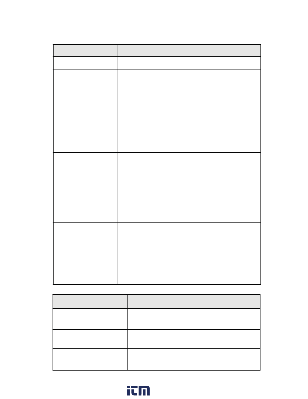
4.5 Output Control Modes (Output Setup)
The S662 supports two independent output channels with four modes of operation:
disabled, timed, latched and boundary.
Output Type Description
Disabled Output
Timed Output
Latch Output
The output channel is inactive.
The timed mode activates an output when a set point
or ‘trigger’ condition is reached. Once active, the
output is held until a specified delay period. The delay
may be between 0.01 and 599.99 seconds.
The output will activate when the specified value is
encountered (SP1 for output 1, SP3 for output 2). If
a timing period is in progress, a new trigger does not
occur. This is referred to as a non-retriggereable
timer.
A RESET will cancel the timed output.
The latch mode activates an output when a ‘trigger’
or set point is reached.
The output will activate when the value is
encountered (SP1 for output 1, SP3 for output 2).
Once activated, the output is held and can be
deactivated only when the specified Latched Until
condition is met. The Latched Until conditions can be
seen in Table 8.
The Boundary mode differs from the other output
types in that it allows the counter to have an output
activate/deactivate automatically within a specified
Boundary Output
range.
Boundary mode activates an output when the count
is between the specified low and high set points
(SP1/SP2 for output 1, SP3/SP4 for output 2.)
Table 8. Latch Until
Latch Until Description
Reset
SP#
RstPos
A front panel or external reset event is required
to deactivate the output.
Output deactivated when set point is
encountered.
Output deactivated when reset position is
encountered.
23
www. .com
[email protected]1.800.561.8187
Page 25

NOTE: The outputs for this counter activate regardless of count direction in all
count modes.
Output 1 Mode
1) To set the Output Control modes, enter the Programming Mode, and press until
the oput 1 setup menu category is reached.
2) Press to continue to the Parameter Name mmode1. The display will flash between mmode1 and the default value of latch. When the display shows latch, press
3) Use the arrow keys to select the correct mode. Press when the correct mode is
ENTER
ENTER
ENTER
selected to accept value and proceed to the next parameter, Output 1 Source.
Output 1 Source
1) After entering the output mode, the display will flash between src 1 and the default
value count1. When the display shows count1, press .
ENTER
2) Use the arrow keys to select the display value to be used for Output 1 comparisons
and match points. Press when the correct source is selected to accept the value
ENTER
and proceed to the next parameter, Batch Reset.
Batch Reset
1) After entering the output 1 source, the display will flash between batrst and the default value no. When the display shows no, press .
ENTER
2) Use the arrow keys to choose whether when the output activates, the counter will
perform a Count 2 reset as well. When the selection is made, press to accept
ENTER
selection and proceed to the next parameter, Output 1 Bindings.
Output 1 Bindings
Which message is display under this parameter depends on the Output 1 Mode selected.
1) After entering the Batch Reset, the display will flash between three choices, depending on the mode previously selected. This is a reminder message only. Press
ENTER
to proceed to the next parameter. See Appendix B for which options correspond
with which parameters.
Output 2
1) After entering the Output 1 parameters, the counter will proceed to the Output 2
Setup. Follow the above instructions for the second output, using Appendix B as a
guide, if necessary.
2) When all selections are entered and accepted into counter memory, counter will
proceed to next menu category, Set Point Setup.
4.6 Set Point Parameters (Set Point Setup)
The S662 has four set point parameters and a special value referred to as Reset Position.
The Reset Position can be referred to as Count Reset Value. SP1 and SP2 are used only
with Output 1, and SP3 and SP4 are used only with Output 2.
24
www. .com
[email protected]1.800.561.8187
Page 26

The SP1 and SP3 parameters are used as Latched or Timed “trigger” values. When a
Boundary Output is selected, SP1 and SP3 become the low boundary values.
The SP2 and SP4 parameters are used as high boundary value or ‘turn-off’ values when
used with other alarm types (i.e. latched until SP4).
The values for all set points are -99999 to 999999. The decimal point will appear according to the current decimal point setting.
Set Point Parameters
1) To set the Set Point parameters, enter the Programming Mode, and press until
the setpnt setup menu category is reached.
2) Press to continue to the Parameter Name sp 1. The display will flash between sp
1 and the default value of 000010. When the display shows 000010, press .
3) Use the arrow keys to enter the correct value of the flashing digit. Use the
key to advance to the next digit. Press when the correct set point is selected to
ENTER
ENTER
RESET
RESET
accept value and proceed to the next parameter, SP 2.
4) Repeat these steps for SP 2, SP 3, and SP 4. The counter will proceed to the next
parameter, Reset Position.
Reset Position
1) To access the Reset Position parameter, enter the Programming Mode, and press
quntil the setpnt setup menu category is reached.
2) Press and then to continue to the Parameter Name rstp 1. The display will
ENTER
flash between rstp 1 and the default value of 000000. When the display shows
000000, press .
3) Use the arrow keys to enter the correct value of the flashing digit. Use the key
to advance to the next digit. Press when the correct position is selected to ac-
ENTER
RESET
ENTER
cept value and proceed to the next parameter name, Count 2 Reset Value. Continue
as above for the reset value for count 2. When finished, the counter will proceed to
the next menu category, Auto Reset Mode (Reset Setup).
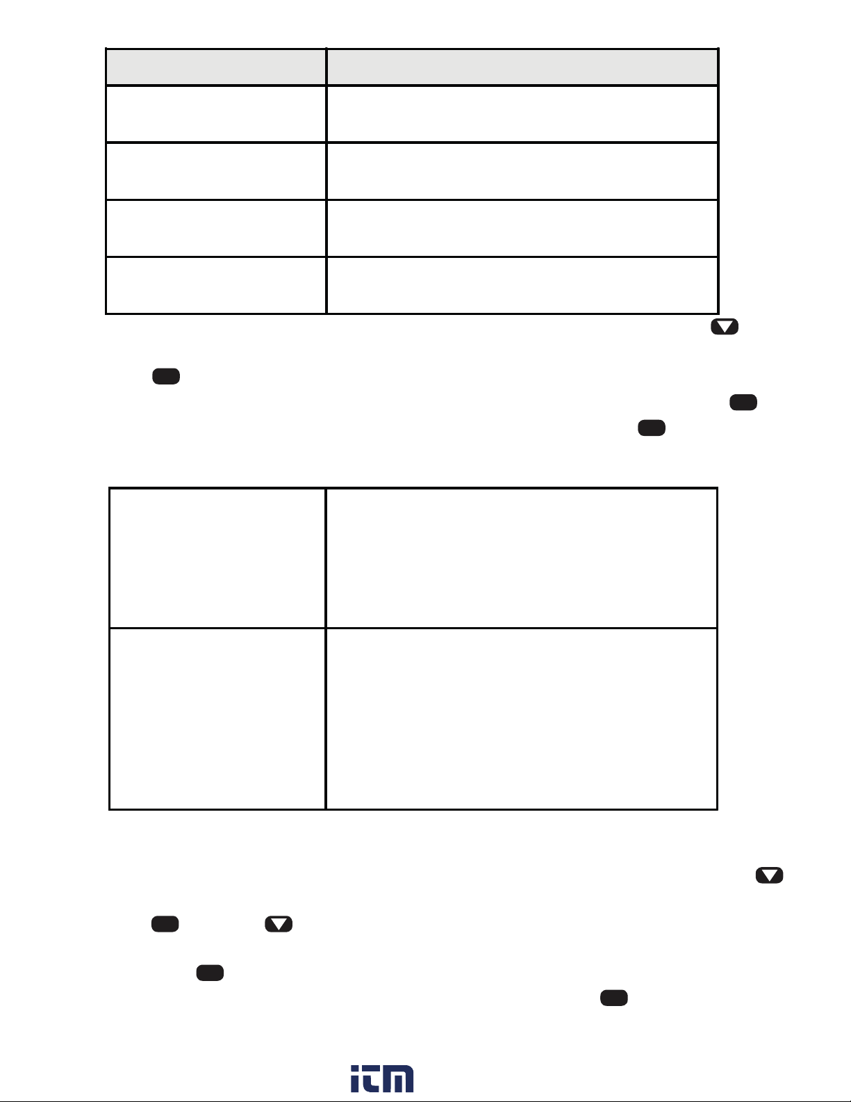
4.7 Auto Reset Operations (Reset Setup)
The S662 has the capability to perform a Count Reset event based upon various conditions. When Auto Reset occurs, the outputs will return to the deactivated status and the
displayed count will return to the value stored in the Reset Position (rstpos) function.
This feature is used in cut-to-length or other applications where an automatic repetitive
cycle is established.
If Count 2 Mode is set to Batch, Count 2 will be increased by one (1) whenever an Auto
Reset occurs. A Batch Reset may link to an output condition. See section 4.5 for details.
25
www. .com
[email protected]1.800.561.8187
Page 27
Mode Description
diSAbL
reset count.
When the selected set point is encountered, reset
Only a front panel or external reset event will
At SP#
event occurs.
Auto Reset occurs after Output 1 times-out
AFtoP1
(Output 1 must be in timed mode).
Auto Reset occurs after Output 2 times-out
AFtoP2
(Output 2 must be in timed mode).
1) To access the Auto Reset Mode, enter the Programming Mode, and press until
the reset setup menu category is reached.
2) Press to continue to the Parameter Name areset. The display will flash between
areset and the default value of disabl. When the display shows disabl, press .
3) Use the arrow keys to scroll through the available options. Press when the cor-
ENTER
ENTER
ENTER
rect mode is selected to accept mode and proceed to the next parameter name, Reset
Button.
rStbtn
(Reset Button)
The Reset Button Inhibit feature disables the front
panel reset button . This can be used to prevent
accidental resets, especially useful when using
the counter as a sequencer. The external (rear
panel) hardware reset input is not affected by this
setting.
PonrSt
(Power ON RESET)
When the Power ON RESET is set to YES, the
counter will always use the Reset Position value
as its initial display/count. With this setting, when
an unexpected power loss occurs, the existing
count will be lost.
When this function is set to NO, the existing count
will be retained after a power loss.
4.8 Miscellaneous Controls
1) To access the Miscellaneous Controls, enter the Programming Mode, and press
until the reset setup menu category is reached.
2) Press , and then to continue to the Parameter Name rstbtn. The display will
flash between rstbtn and the default value of enable. When the display shows enable, press .
3) Use the arrow keys to select either Enable or Disable. Press when the correct
mode is selected to accept selection and proceed to the next parameter name, Power
On Reset.
ENTER
ENTER
ENTER
26
www. .com
[email protected]1.800.561.8187
Page 28

4) The display will flash between Ponrst and the default no. When the display shows
no, press .
5) Use the arrow keys to select either no or yes. Press when the correct mode is se-
ENTER
ENTER
lected.
6) The display will now show end. If you are finished programming the S662, press .
ENTER
If not, use the arrow keys to back up to the necessary parameter.
Appendix A: Technical Specifications
A.1 Functional Specifications
Count modes
supported
Batch modes
supported
Count Inputs
Miscellaneous
inputs
Count range
(internal)
Maximum count rate
Min pulse width
Display Digits
Count/Direction, Add-Add, Add-Subtract, Subtract-Subtract,
Quadrature and Reverse Quadrature, Rate, and Batch
Dual mode: Primary and Secondary counts share common
input, but with independent scaling and resets.
Batch mode: Secondarey Count incremented when Primarey
Count Auto Reset occurs.
2: Channel A (Primary) and Channel B (Secondary / Dir
control)
2: Reset (Count Reset) and User (Count Inhibit).
-2,147,483,648 to +2,147,483,648
20 Khz (Standard and Quadrature X1 modes)
5 Khz (Quadrature X4 mode)
5 uS (Standard mode)
6-digit, 7-segment with leading zero blanking
Display Decimal
Point
Display LEDs
Display Range
Output channels
Output modes
Delay times
Output Response
time
Multi-tasking
Operation
User-programmable
Red 0.56" (14.2mm), high efficiency
- 99,999 to + 999,999 (Independent of decimal position)
2, with front panel indicator for each
Disabled, Timed, Latching, and Boundary
0.01 to 599.99 sec -2.5 ms/+15ms
Latched and timed modes: < 5ms
Boundary mode: < 15 ms
Batch: <15 ms
Count and output control maintained while in programming
mode.
27
www. .com
[email protected]1.800.561.8187
Page 29
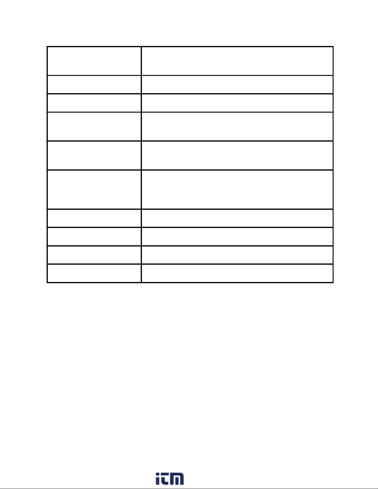
A.2 Electrical, Environmental and Mechanical
Power
Requirements
Power Consumption
Reset Input Signal
Storage
Temperature
Operating
Temperature
Relative Humidity
Bezel
AC Supply: 120 or 240 VAC, ±10%
3VA
Active Low: 0.2 VDC = active
-10 to 60°C
0 to 40°C
0 to 80% for temperatures less than 32°C,
decreasing linearly to 50% at 40°C. (Noncondensing)
3.93" x 2.04" x 0.52" (99.8 x 51.8 x 13.3mm)
Panel Cutout
Case Depth
Weight
3.62" x 1.77" (92 x 45 mm) 1/8 DIN
3.24" (82mm)
9.0 oz. (255.1g)
28
www. .com
[email protected]1.800.561.8187
Page 30
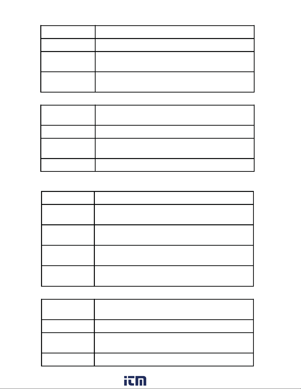
Standard input module
Input Channels
Count edge
Input Sources
Input
Impedance
A & B channels
User Channel
Low pass filter
Max voltage
A, B and User
High to low transition (A and B channels)
Switch contact, CMOS or TTL logics, PNP or NPN
devices
Sinking: 10K, 5% Res. Pull-up to (9.0 - 16 VDC) ±10%
Sourcing: 5.1K, 5% Res. Pull-down to common
Input Thresholds
Low Bias mode:VLT = 1.6V ±10% VUT = 3.6V ±10%
High Bias mode:VLT = 5.0V ±10% VUT = 7.0V ±10%
VLT = 0.2V (min) VUT = 3.0V (max)
Frequency < 200Hz (0 to 10V input square wave at
50% duty cycle)
A, B and User channels 30VDC maximum sustained
Quadrature input module
Input Channels
Input Inversion
Operation
modes
Input Sources
Input
Impedance
A & B channels
User Channel
A, B and User
User-selectable input polarity. A and B channel
polarity selective in standard mode only.
Standard, Quadrature X1 and Quadrature X4
Switch contact, CMOS or TTL logics, PNP or NPN
devices quadrature (single-ended) encoders
Sinking: 10K, 5% Res. Pull-up to (9.0 - 16 VDC) ±10%
Sourcing: 5.1K, 5% Res. Pull-down to common
Input Thresholds
Low Bias mode:VLT = 1.6V ±10%VUT = 3.6V ±10%
High Bias mode:VLT = 5.0V ±10% VUT = 7.0V ±10%
VLT = 0.9V (min) VUT = 3.15V (max)
Low pass filter
Max voltage
Frequency < 200Hz (0 to 10V input square wave at
50% duty cycle)
A, B and User channels 30VDC maximum sustained
29
www. .com
[email protected]1.800.561.8187
Page 31
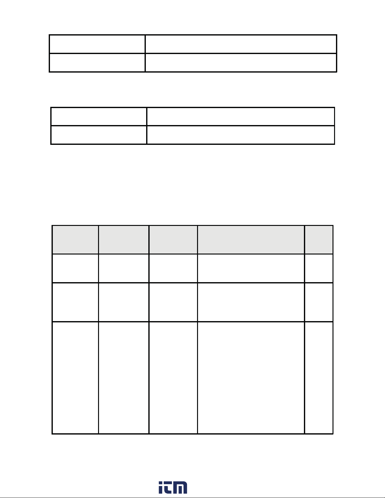
Single / Dual Relay Modules
Contact Rating
Mechanical Life
Isolated 12V Excitation Module
Exitation Output
Exitation Isolation
5 Amps 250 VAC
1,000,000 cycles
100 mA at 12 VDC ±5%
1500 V
Appendix B: Programming Quick Reference
If you are unfamiliar with navigating menus in the S662, see section 3. Each parameter is listed in the order of appearance in the menu system. Refer to the paragraph indicated in the Tech Note column for technical details on a particular parameter.
Tip: Photocopy these pages to mark settings on.
Menu
Category
Parameter
Name
PASS 000
ACCESS<—
CHPASS 000*
Choices /
Format
—>dEniEd
Description Tech
Password Entry and
Verification
Password Fail
Appears if incorrect
password entered
Password Change
Appears if correct
password entered
000 = Password
protection disabled
001-099 = Secures all
parameters
100-999 = Enable
SPs/ResPos access in
display mode
Note
4.1
4.1
4.1
* = factory default settings
30
www. .com
[email protected]1.800.561.8187
Page 32

Menu
Category
Parameter
Name
Choices /
Format
Description Tech-
Note
inPut
SEtuP
Count 1
SEtuP
A CHAn uP*
doW n
quad
r quad
b CHAn dir*
uP
doW n
SCALE1 01.0000*
dP 1 000000 *
000000.
00000.0
0000.00
000.000
00.0000
0.00000
Chan A Mode
Select count mode of A
channel.
Chan B Mode
Select count mode for B
channel.
Note: if A channel set to
quad or Rquad, this item
is not accessible.
Count 1 Scale
Set Display Value 1
scaling multiplier.
Values: -9.9999 to
99.9999
Count 1 DP Display
Value 1 (Count1)
Decimal Point location.
Affects appearance of
RstP1 and any
associated Set Point
parameters.
4.2
4.2
4.3
4.3
* = factory default settings
31
www. .com
[email protected]1.800.561.8187
Page 33

Menu
Category
Parameter
Name
Choices /
Format
Description Tech
Note
Count 2
SEtuP
M m odE duAL*
bAtCH
PrESCL 1.0*
0.1
0.01
0.001
SCALE 2 01.0000*
dP 2 000000*
000000.
00000.0
0000.00
000.000
00.0000
0.00000
Batch Mode
Display value 2 (Count
2) mode. Defines the
counting mode for batch
count.
Count 2 Prescale
Set prescaling multiplier
for Display Value 2.
Count 2 Scale
Set Display Value 2
(Count 2) scaling
multiplier.
Values:
99.9999.
Count 2 DP
Display Value 2 Decimal
Point location. Affects
appearance of RstP2
and any associated Set
Point parameters.
-9.9999 to
4.4
4.4
4.4
4.4
* = factory default settings
32
www. .com
[email protected]1.800.561.8187
Page 34

Menu
Category
Parameter
Name
Choices /
Format
Description Tech
Note
oPut 1
SEtuP
M m odE1 diSAbLE
tiMmEd
LAtCH*
bound
SrC 1 Count1*
Count2
bAtrSt no*
YES
Output 1 Mode
Set the mode of
operation for Output 1.
Can be disabled, timed,
latched or boundary
mode.
Output 1 Source
Select which Display
value to be used for
Output 1 comparisons /
matchpoints. See also
SP1 and SP2.
Batch Reset
When output activates,
perform Count 2 Reset
as well. Appears only if
SrC 1 = Count2.
4.5
4.5
4.5
* = factory default settings
33
www. .com
[email protected]1.800.561.8187
Page 35

Menu
Category
Parameter
Name
Choices /
Format
Description Tech
Note
tiMmEd<—
LAtCHED<—
SP1=Lo <—
dELAY1 010.00*
untiL1 ReseT*
—>At SP1
—>AtSP1*
—>SP2=Hi
SP1
SP2
SP3
SP4
rStP1
Output 1 Bindings
Reminder message
indicates which and how
the set points are used
for comparison. Which
message is displayed
depends on the Output
1 Mode or Source
selected.
Delay 1
Output 1 delay time.
Appears only if Output 1
mode set to timed.
Until 1
Output 1 latched until
parameter. Appears only
if MmodE1 = LAtCH and
SrC1 = Count1.
4.5
4.5
4.5
oPut 2
SEtuP
MmodE2 diSAbL
tiMmEd
LAtCH*
bound
* = factory default settings
Output 2 Mode
Set the mode of
operation for Output 2.
Can be disabled, timed,
latched or boundary
mode.
4.5
34
www. .com
[email protected]1.800.561.8187
Page 36

Menu
Category
Parameter
Name
Choices /
Format
Description Tech
Note
SrC 2 Count1*
Count2
bAtrSt no*
YES
tiMmEd<—
LAtCHEd<—
SP3=Lo<—
—>At SP3
—>AtSP3*
—>SP4=Hi
Output 2 Source
Select which Display
value to be used for
Output 2 comparisons /
matchpoints. See also
SP3 and SP4.
Output 2 Batch Reset
When output activates,
perform Count 2 Reset
as well.
Output 2 Bindings
Reminder message
indicates which and how
the set points are used
for comparison. Which
message is displayed
depends on the Output
2 Mode or Source
selected.
4.5
4.5
4.5
* = factory default settings
35
www. .com
[email protected]1.800.561.8187
Page 37

Menu
Category
Parameter
Name
Choices /
Format
Description Tech
Note
SP2 000020*
SP3 000030*
SP4 000040*
SP2
Set point #1 High.
Values:-99999 to
999999. Decimal point
will appear according to
the current Output 1
Source setting.
SP3
Set point #2 Low.
Values: -99999 to
999999. Decimal point
will appear according to
the current Output 2
Source setting.
SP4
Set point #2 High.
Values: -99999 to
999999. Decimal point
will appear according to
the current Output 2
Source setting.
4.6
4.6
4.6
* = factory default settings
36
www. .com
[email protected]1.800.561.8187
Page 38

Menu
Category
Parameter
Name
Choices /
Format
Description Tech
Note
SEtPnt
SEtuP
dELAY 010.00*
untiL2 Reset*
SP1
SP2
SP3
SP4
RstP 1
SP1 000010 *
Delay 2
Output 2 delay time.
Appears only if Output 2
mode set to timed.
Until 2
Output 2 latched until
parameter. Appears only
if M m ode2 = latch and
SRC2 = Count1.
SP1
Set point #1 Low.
Values: -99999 to 99999.
Decimal point will appear
according to the current
Output 1 Source
setting.
4.5
4.5
4.6
Menu
Category
Parameter
Name
rStP 1 000000*
rStP 2 000000*
Choices /
Format
Description Tech
Count 1 Preset Value
Count 1 value is set to this
when an Auto or Manual
Reset event occurs. Values:
-99999 to 999999. Decimal
point will appear according
to the user-programmed
Count DP 1 position.
Count 2 Preset Value
Count 2 value is set to this
when an Auto or Manual
Reset event occurs. Values:
-99999 to 999999. Decimal
point will appear according
to the user-programmed
Count DP 2 position.
Note
4.6
4.6
* = factory default settings
37
www. .com
[email protected]1.800.561.8187
Page 39

Menu
Category
Parameter
Name
Choices /
Format
Description Tech
Note
rESEt
SEtuP
End
ArESEt diSAbLE*
At SP1
At SP2
At SP3
At SP4
AFtoP1
AFtoP2
rStbtn EnAbLE*
disAbLE
PonrSt no*
YES
Auto Reset Mode
Selects when an auto
reset function is to occur.
Disabled, at a setpoint or
after output times out.
See also the RSTP1
parameter in the Setpnt
Setup category
Reset Button Enable or
disable front panel reset
button.
Power On Reset Select
whether count reset
event will occur at
power-up.
Exit Programming
Menu
4.7
4.8
4.8
* = factory default settings
38
www. .com
[email protected]1.800.561.8187
 Loading...