

Simpson Electric Company S66112110, S66112200, S66111200, S66111000, S66112100 User manual
...Page 1
S661
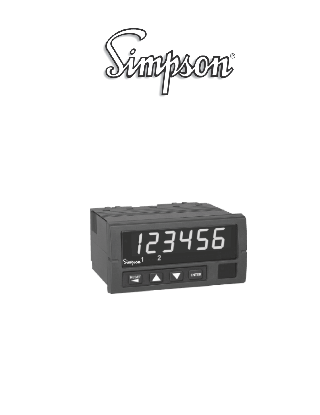
Rate Counter
Operation Manual
Find Quality Products Online at: [email protected]
www.GlobalTestSupply.com
Page 2
About this Manual
To the best of our knowledge and at the time written, the information contained in this
document is technically correct and the procedures accurate and adequate to operate this
instrument in compliance with its original advertised specications.
Notes and Safety Information
This Instruction Manual contains warning headings that alert the user to check for hazardous
conditions. These appear throughout this manual where applicable, and are dened below.
To ensure the safety of operating performance of this instrument, these instructions must be
adhered to.
Warning, refer to accompanying documents.
Attention, consulter les documents d’accompagnement.
Caution, risk of electric shock.
Attention, risque de choc électrique.
Warranty and Returns
SIMPSON ELECTRIC COMPANY warrants each instrument and other articles manufactured
by it to be free from defects in material and workmanship under normal use and service, its
obligation under this warranty being limited to making good at its factory or other article of
equipment which shall within one (1) year after delivery of such instrument or other article of
equipment to the original purchaser be returned intact to it, or to one of its authorized service
centers, with transportation charges prepaid, and which its examination shall disclose to its
satisfaction to have been thus defective; this warranty being expressly in lieu of all other warranties expressed or implied and of all other obligations or liabilities on its part, and SIMPSON
ELECTRIC COMPANY neither assumes nor authorizes any other persons to assume for it any
other liability in connection with the sales of its products.
This warranty shall not apply to any instrument or other article of equipment which shall have
been repaired or altered outside the SIMPSON ELECTRIC COMPANY factory or authorized
service centers, nor which has been subject to misuse, negligence or accident, incorrect wiring
by others, or installation or use not in accord with instructions furnished by the manufacturer.
Under the normal eld usage there is no need to remove the front bezel of this product. The
front bezel of this product should only be removed by a qualied technician.
1
Find Quality Products Online at: [email protected]
www.GlobalTestSupply.com
Page 3

Contents
1 Product Description. . . . . . . . . . . . . . . . . . . . . . . . . . . . . . . . . . . . . . . . . . . . .3
1.1 General Description. . . . . . . . . . . . . . . . . . . . . . . . . . . . . . . . . . . . . . . . . . 3
1.2 Part Number Identification. . . . . . . . . . . . . . . . . . . . . . . . . . . . . . . . . . . . . 4
1.3 Option Module Summary. . . . . . . . . . . . . . . . . . . . . . . . . . . . . . . . . . . . . . 4
2 Hardware Setup. . . . . . . . . . . . . . . . . . . . . . . . . . . . . . . . . . . . . . . . . . . . . . . 6
2.1 Panel Installation. . . . . . . . . . . . . . . . . . . . . . . . . . . . . . . . . . . . . . . . . . . . 6
2.2 Removing / Installing Option Modules. . . . . . . . . . . . . . . . . . . . . . . . . . . . 7
2.3 120/240 VAC Power Module. . . . . . . . . . . . . . . . . . . . . . . . . . . . . . . . . . . 8
2.4 Standard Input Module. . . . . . . . . . . . . . . . . . . . . . . . . . . . . . . . . . . . . . . .8
2.5 Quadrature Input Module. . . . . . . . . . . . . . . . . . . . . . . . . . . . . . . . . . . . . 11
2.6 Excitation Module. . . . . . . . . . . . . . . . . . . . . . . . . . . . . . . . . . . . . . . . . . .14
2.7 Single and Dual Relay Modules. . . . . . . . . . . . . . . . . . . . . . . . . . . . . . . .15
3 Display & Keypad Controls. . . . . . . . . . . . . . . . . . . . . . . . . . . . . . . . . . . . . . 16
3.1 Display. . . . . . . . . . . . . . . . . . . . . . . . . . . . . . . . . . . . . . . . . . . . . . . . . . . 16
3.2 Display Error Messages. . . . . . . . . . . . . . . . . . . . . . . . . . . . . . . . . . . . . . 17
3.3 What the Keys Do in Display Mode. . . . . . . . . . . . . . . . . . . . . . . . . . . . . 18
3.4
3.5 Special Start-Up Modes. . . . . . . . . . . . . . . . . . . . . . . . . . . . . . . . . . . . . . 21
What the Keys Do in the Programming Mode. . . . . . . . . . . . . . . . . . . . . 18
4 Counter Operations and Parameters. . . . . . . . . . . . . . . . . . . . . . . . . . . . . . 21
4.1 Password and Security Controls. . . . . . . . . . . . . . . . . . . . . . . . . . . . . . . 22
4.2 A/B
Channel Options. . . . . . . . . . . . . . . . . . . . . . . . . . . . . . . . . . . . . . . . 23
4.3 Rate (Frequency) Scaling and Display. . . . . . . . . . . . . . . . . . . . . . . . . . .25
4.4 Output Control Modes. . . . . . . . . . . . . . . . . . . . . . . . . . . . . . . . . . . . . . . 27
4.5 Set Point Parameters. . . . . . . . . . . . . . . . . . . . . . . . . . . . . . . . . . . . . . . .28
4.6 Miscellaneous Controls. . . . . . . . . . . . . . . . . . . . . . . . . . . . . . . . . . . . . . .2
Appendix A: Technical Specifications. . . . . . . . . . . . . . . . . . . . . . . . . . . . . . . 30
A.1 Functional Specifications. . . . . . . . . . . . . . . . . . . . . . . . . . . . . . . . . . . . . 30
A.2 Electrical, Environmental and Mechanical Specifications. . . . . . . . . . . . 31
Appendix B: Programming Quick Reference. . . . . . . . . . . . . . . . . . . . . . . . . . 33
9
2
Find Quality Products Online at: [email protected]
www.GlobalTestSupply.com
Page 4
1 Product Description
1.1 General Description
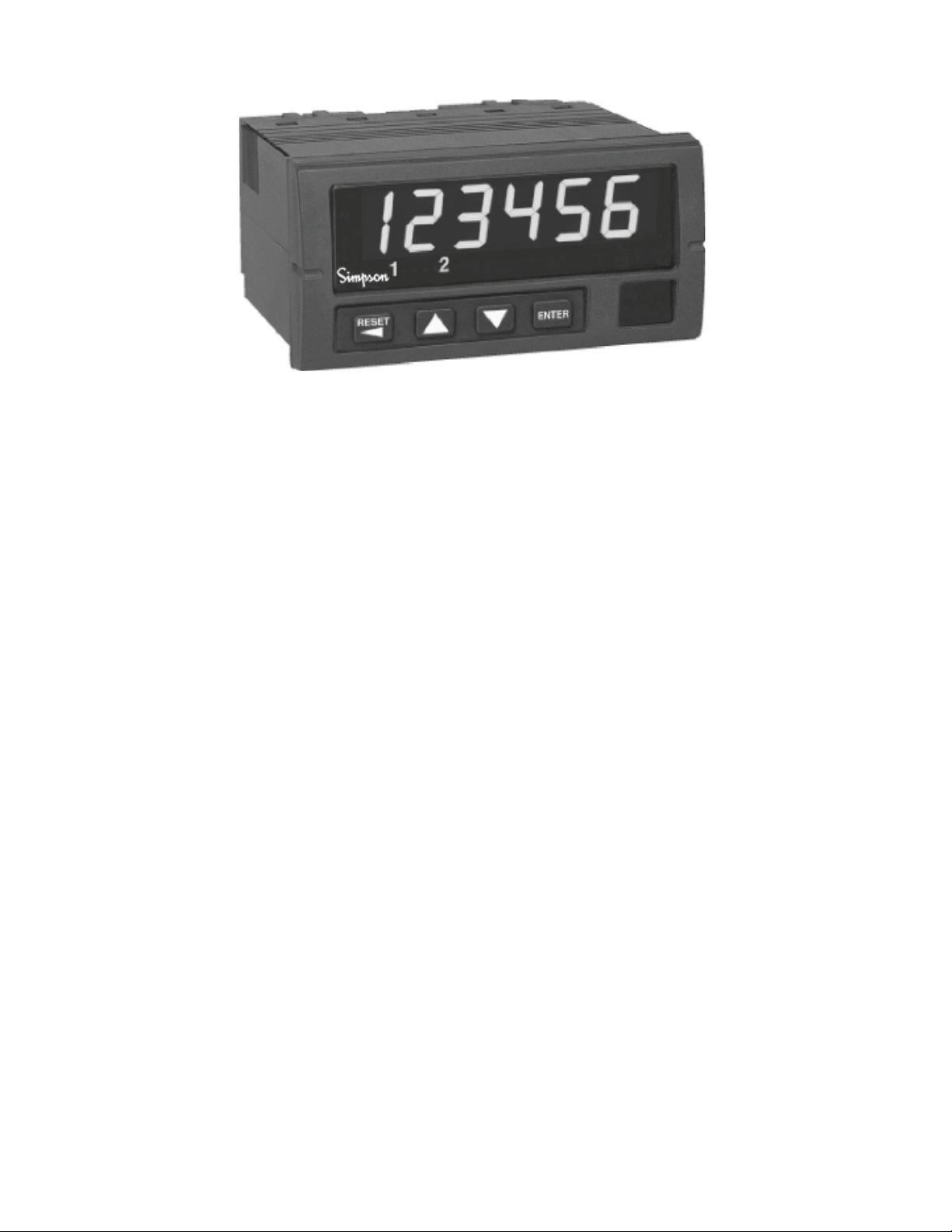
The S661 rate counter fits a 1/8 DIN standard cutout and is perfect for tight spaces,
extending only 3.24” (82mm) behind the panel. The unit is UL listed. The unit is for indoor use at altitudes up to 2000m, temperatures between 0° and 40°C and installation
category III, pollution degree 2.
The counter is powered from 120 or 240 VAC. The nonvolatile EEPROM retains all
programming and count information when power is removed or interrupted.
Display scaling, preset values and all menu functions are easily programmed from the
front panel, following easy-to-use word prompts. Front panel reset disable and password lockout protection features guard against unauthorized or accidental changes.
The counter accepts count rates up to 30 kHz and pulses from different types of sensors, including Quadrature, CMOS or TTL circuits and PNP or NPN devices.
The optional, field-replaceable single/dual relay module enhances the counter from a
passive display device to an integral control element for your application. The counter
has latching, boundary or timed (0.01 to 599.99 seconds) output modes.
An optional 12 VDC (100mA) excitation output module can provide power for external
sensors.
3
Find Quality Products Online at: [email protected]
www.GlobalTestSupply.com
Page 5
1.2 Part Number Identification
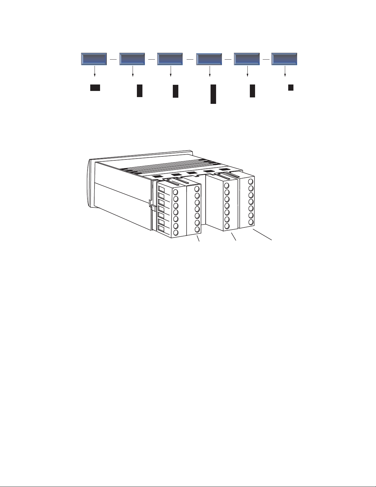
The following matrix indicates the configuration of your S661 counter.
Basic Unit
S661
Power Supply
120 VAC
240 VAC
1
2
Quadrature
1.3 Option Module Summary
Input
Standard
1
2
1
Input Excitation Power
Output
None
One relay
Two Relays
2
0
1
2
4
Supply
Excitation
None
12VDC
Other
0
1
None
0
5
Output
Figure 1. Option Module Slots (Rear View)
The S661 is a modular product which uses field configuring slide-in modules. The
modules slide easily into the rear of the counter.
Figure 1 displays the functional assignments for each module position.
4
Find Quality Products Online at: [email protected]
www.GlobalTestSupply.com
Page 6
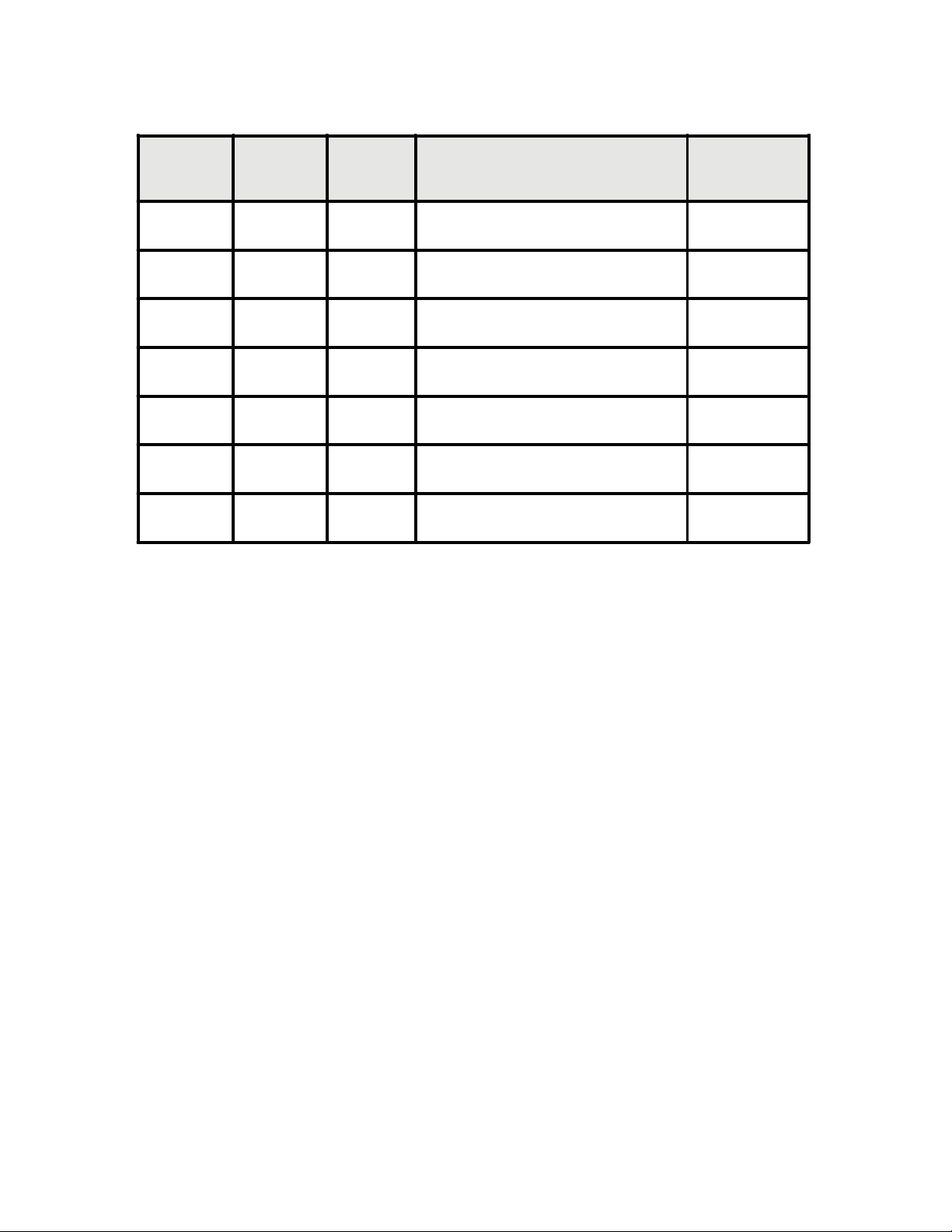
Table 1 describes available option modules for the S661.
Table 1. Option Module Summary
Module
slot
1 Input Standard Input Module
1 Input Quadrature Input Module
2Ext 45064 12 VDC Excitation Module
4Power 120 VAC Power Module
4Power 240 VAC Power Module
5 Output 45062Dual Relay Module
5 Output 45063 Single Relay Module
Type P/N Description
See
Section
2.4
2.5
2.6
2.3
2.3
2.7
2.7
5
Find Quality Products Online at: [email protected]
www.GlobalTestSupply.com
Page 7
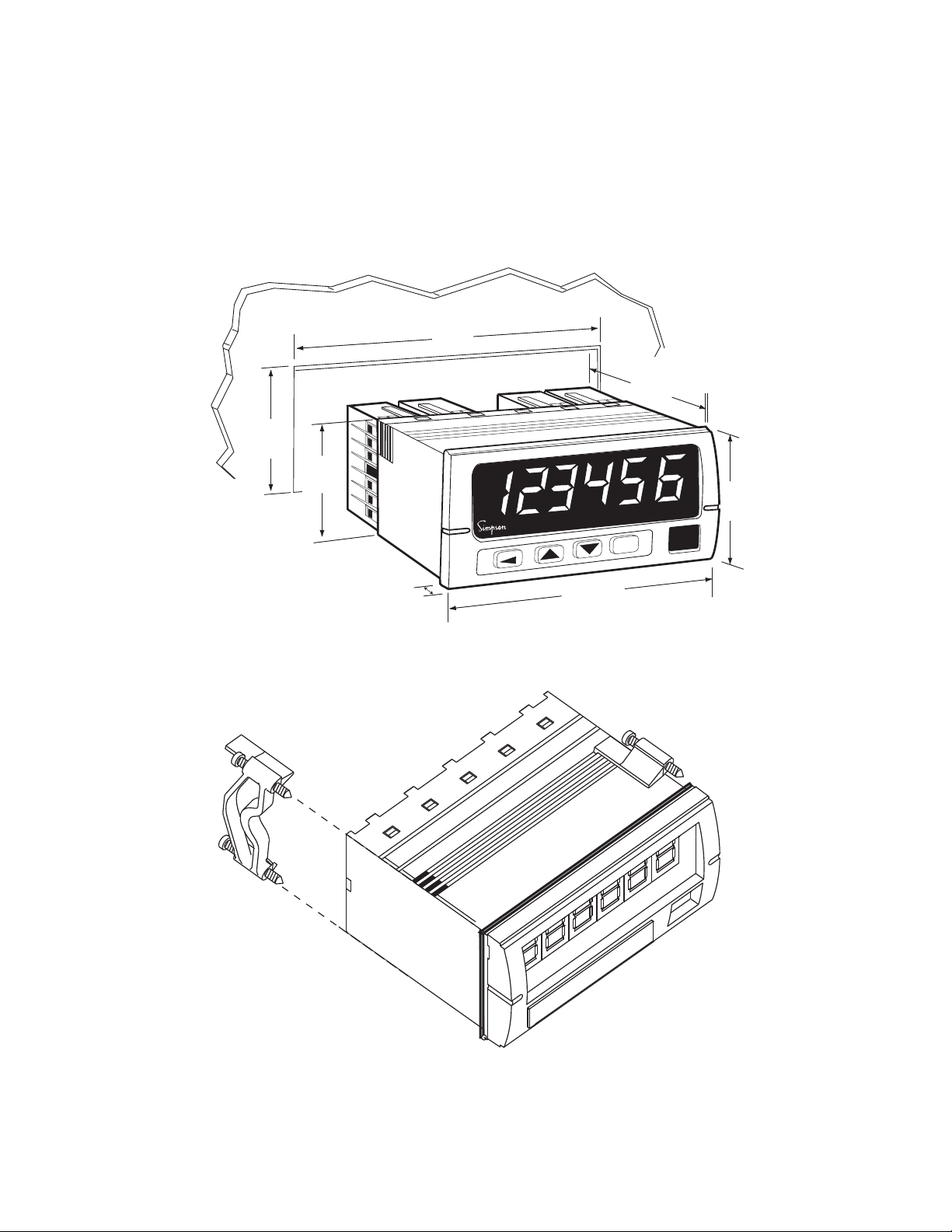
2 Hardware Setup
2.1 Panel Installation
The S661 1/8 DIN counter requires a standard 1/8 DIN panel cutout of 1.77” (45mm)
high by 3.62” (92mm) wide. To install the counter into a panel cutout, remove the clips
from the side of the counter. Slide the counter through your panel cutout, then slide
the mounting clips back on. Press evenly to ensure a proper fit.
3.62"
92mm
3.24"
82mm
1.77"
45mm
1.74"
44mm
.52"
13.2 mm
%
RESET
99.8 mm
ENTER
3.93"
2.04"
51.8mm
Figure 2. Counter and Panel Cut-Out Dimensions
Figure 3. Panel Mounting Clips
6
Find Quality Products Online at: [email protected]
www.GlobalTestSupply.com
Page 8
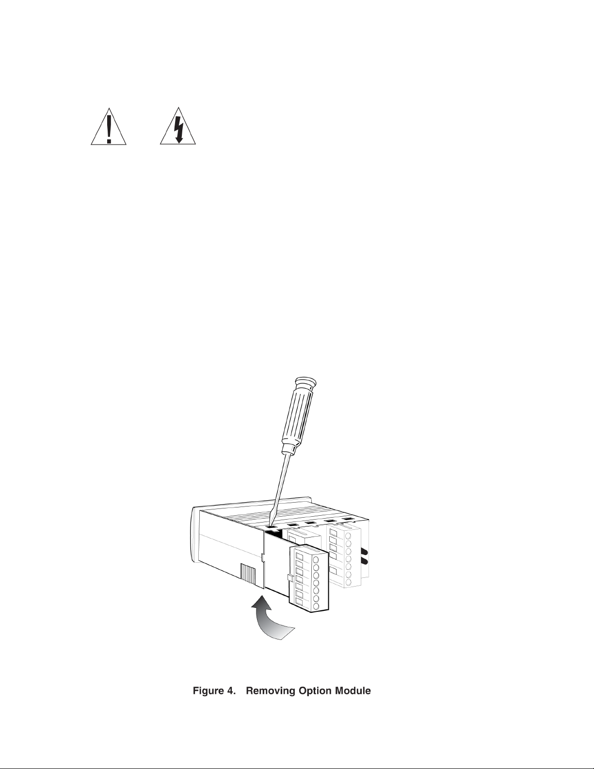
2.2 Removing / Installing Option Modules
Shut power off before removing or installing any option modules
Couper le courant avant de retirer ou d’installer des modules optionnels
1. Remove module from case by inserting a screwdriver into tab slot opening at top of input
module. Apply pressure to release module from case. Repeat procedure for tab located on
underside of module and then slide module away from the case.
2. Refer to appropriate sections to congure switches or jumpers for proper operation.
Table 1 can be used to identify modules and their associated detail paragraph.
3. Install module by carefully aligning module edges with slots in case and pressing forward
until tabs (on top and bottom) engage.
7
Find Quality Products Online at: [email protected]
www.GlobalTestSupply.com
Page 9
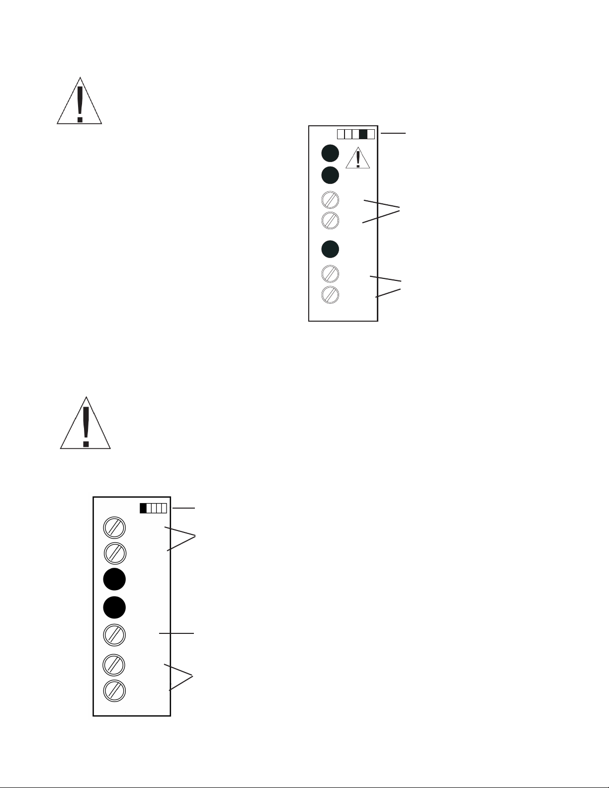
2.3 120/240 VAC Power Module
Remove power before wiring option modules.
Coupez l’alimentation avant de raccorder les modules optionnels.
The AC power module allows the S661 to be
operated from standard 50/60 Hz line power.
The power module will be congured as 120
VAC or 240 VAC per markings on the back
panel. Ensure the input rating of the supply
matches your line voltage. The power supply
module has provisions for a hard-wire Alarm
Reset. This control can be a switch, relay
contact or solid state device. Actuation is
immediate upon an active Low for at least
2.5ms to this terminal. The reset circuit is
independent of the power circuit.
Denotes modules position 4 at rear
of counter
~
~
VAC
VAC
RESET
COMMON
POWER
Power Supply 120 VAC or 240 VAC
power connection
Remote Reset
Active low 0.2V performs primary
reset
Figure 5. AC Power Module
NOTE: A fusible link is not provided on this module.
A ½ Amp Time Delay fuse, Bussman MDL ½, or similar is required.
Never connect AC mains (hot or neutral) to the Reset or Common terminals!
Ne jamais brancher sur secteur (chaudes ou neutres) pour la réinitialisation
ou terminaux communs!
2.4 Standard Input Module
Denotes module position 1 at rear of counter
A INPUT
COMMON
USER
INPUT
B INPUT
COMMON
Primary Input
Connect the input signal to A INPUT and COMMON
Display Hold
Active low
‘Freezes’ Display Value
Secondary Input
Direction Control or count pulse input
IINPUT
Figure 6. Standard Input Module
8
Find Quality Products Online at: [email protected]
www.GlobalTestSupply.com
Page 10
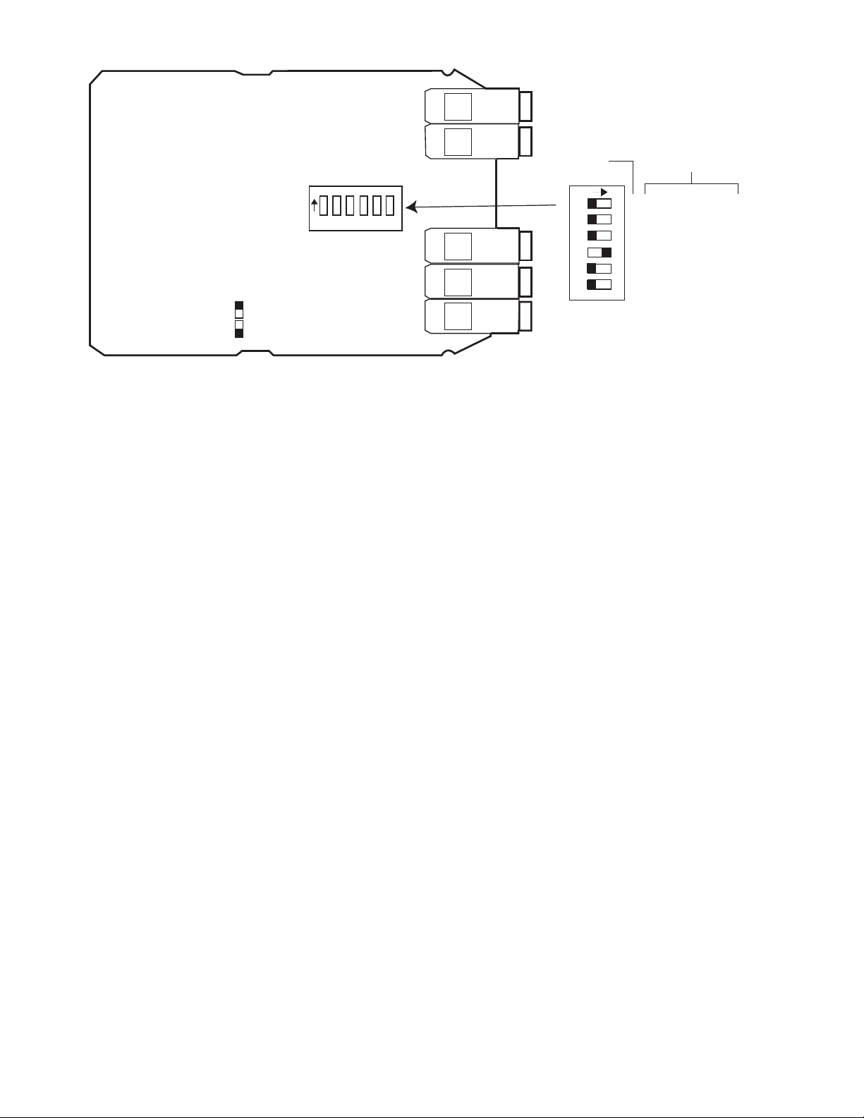
DIP Switch
(Shown for TTL Factory Settings)
FUNCTION
B Bias Off=Hi On=Lo
B Freq Off=Hi On=Lo
B Off= Sink On= Source
A Bias Off=Hi On=Lo
A Freq Off=Hi On=Lo
A Off= Sink On= Source
Dipswitch Legend
= ON
= OFF
CHANNEL
1 2 3 4 5 6
1 2 3 4 5 6
Note: Refer to specifications
for DIP switch function
electrical characteristics
Figure 7. Standard Input Module Default Settings
DIP switch SW1, figure 7, is used to set up the counter to conform to the electrical
characteristics of the sensor or signal being detected. Switch positions 1-3 configure channel B, while switches 4-6 configure channel A. These switches select bias
(threshold voltages), low pass filter (enable/disable) and sensor type (Sink or Source).
Refer to the documentation that accompanied the sensor for related information. The
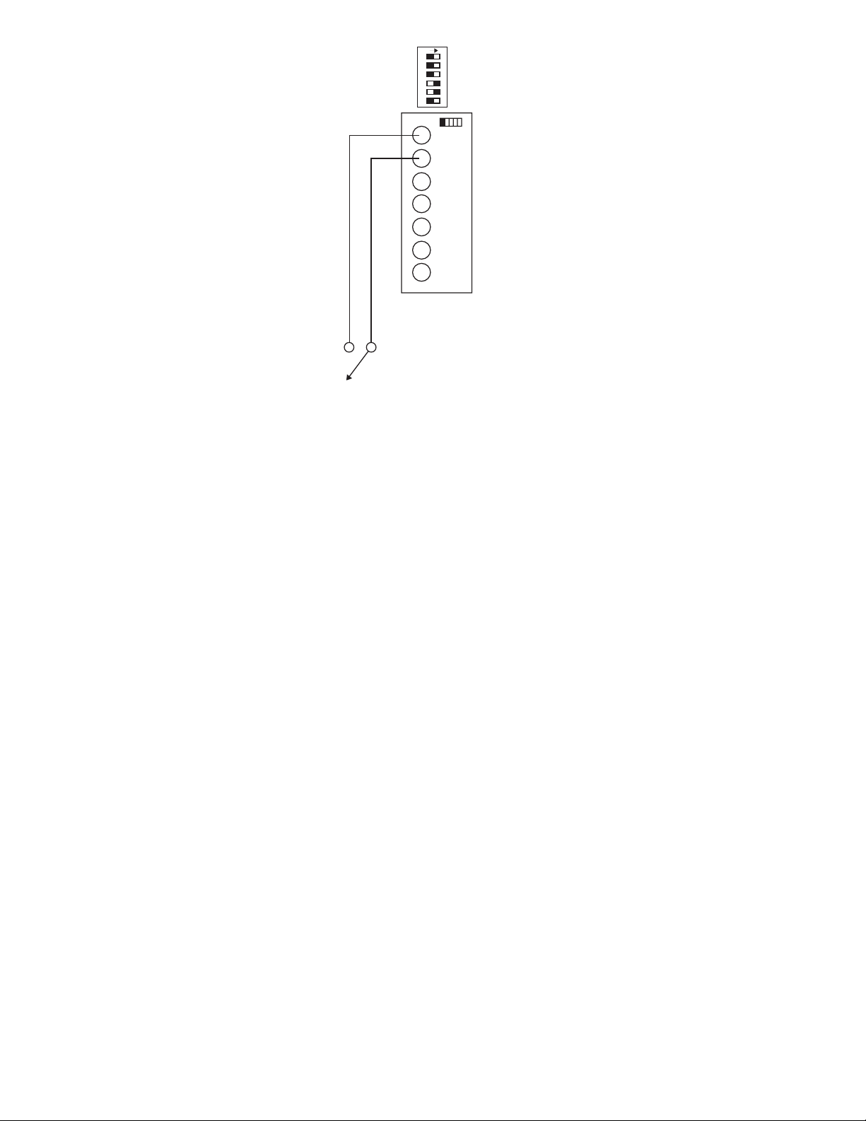
sensor can most likely be matched to one of the typical switch settings shown in figure
8 and figure 8a.
Note: The input boards are designed so that selecting sourcing or sinking is
based on the type of sensor that is being used. If a PNP (sinking) sensor is being used, set the input board for sinking also (switched 3 and 6 = OFF).
If channel B is not used, default settings for switch positions 1 through 3 should be selected. Default settings are provided in Table 2.
The input module also provides for a user input signal. On the S661, this input performs a Display Hold. While active, the rate value shown on the display is “frozen.”
Internal measurements and output controls continue to operate.
9
Find Quality Products Online at: [email protected]
www.GlobalTestSupply.com
Page 11
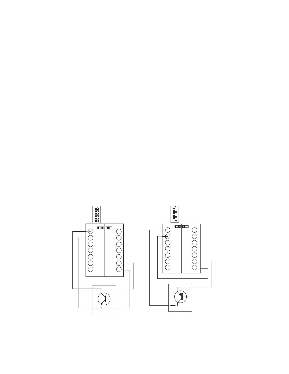
The S661 can accept inputs from many different sensors. The A and B channels may
+
be configured independently as shown in Table 2. Figures 8 and 8a have examples of
some typical sensors and the wiring connections that would be used.
Table 2. Standard Input Module DIP Switch Settings
* = Factory Default setting
1 B Channel Bias: OFF = Hi* VLT = 5.0 V VUT = 7.0V (+/- 10%)
ON = Low VLT = 1.6 V VUT = 3.6V (+/- 10%)
2 B Channel Frequency: OFF = Hi* (low pass filter disabled)
ON = Lo (low pass filter enabled)
3 B Channel Sensor: OFF = Sinking* (internal pull-up enabled)
ON = Source (internal pull-down enabled)
4 A Channel Bias: OFF = Hi VLT = 5.0 V VUT = 7.0V (+/- 10%)
ON = Low* VLT = 1.6 V VUT = 3.6V (+/-10%)
5 A Channel Frequency: OFF = Hi* (low pass filter disabled)
ON = Lo (low pass filter enabled)
6 A Channel Sensor Type: OFF = Sinking* (internal pull-up enabled)
ON = Source (internal pull-down enabled)
ON
1 2 3 4 5 6
LOW BIAS
LOW FREQUENCY
SOURCING
A INPUT
COMMON
USER
INPUT
B INPUT
ISO+12V
ISOCOM
COMMON
EXCITATION
INPUT
__
---
+
_
HIGH FREQUENCY
HIGH BIAS
SINKING
OUTPUT
ON
1 2 3 4 5 6
LOW BIAS
LOW FREQUENCY
SOURCING
A INPUT
COMMON
USER
INPUT
B INPUT
ISO+12V
ISOCOM
COMMON
INPUT
EXCITATION
HIGH BIAS
__
---
HIGH FREQUENCY
+
_
SINKING
COMMON
NPN SENSOR
PNP SENSOR
Figure 8. Sensor Connection Examples
10
Find Quality Products Online at: [email protected]
www.GlobalTestSupply.com
Page 12
ON
1 2 3 4 5 6
HIGH FREQUENCY
HIGH BIAS
SINKING
DRY CONTACT
LOW BIAS
LOW FREQUENCY
SOURCING
A INPUT
COMMON
USER INPUT
B INPUT
COMMON
INPUT
Figure 8a. Sensor Input example
2.5 Quadrature Input Module
The Quadrature / Universal Input Module has two operational modes: Quadrature
mode and Standard mode. Quadrature mode is selected by positioning JP1 and JP2
on pins 1 and 2. Standard mode is selected by placing JP1 and JP2 on pins 2 and 3
(see Figure 10 for details). The Quadrature mode supports a wide range of encoders
including the Simpson SE series.
While in Standard mode, this module works similarly to the Standard Input module,
with the added capability to selectively invert A, B, and User input signals. The Input
module also provides for a User input signal. On the S661 this input serves as a Display Hold. While active, the rate value shown on the display is “frozen.” Internal measurements and output controls continue to operate.
NOTE: If B channel is not going to be used, use the default switch settings for
SW1 positions 1 through 3. Default settings are provided in Table 3.
11
Find Quality Products Online at: [email protected]
www.GlobalTestSupply.com
Page 13
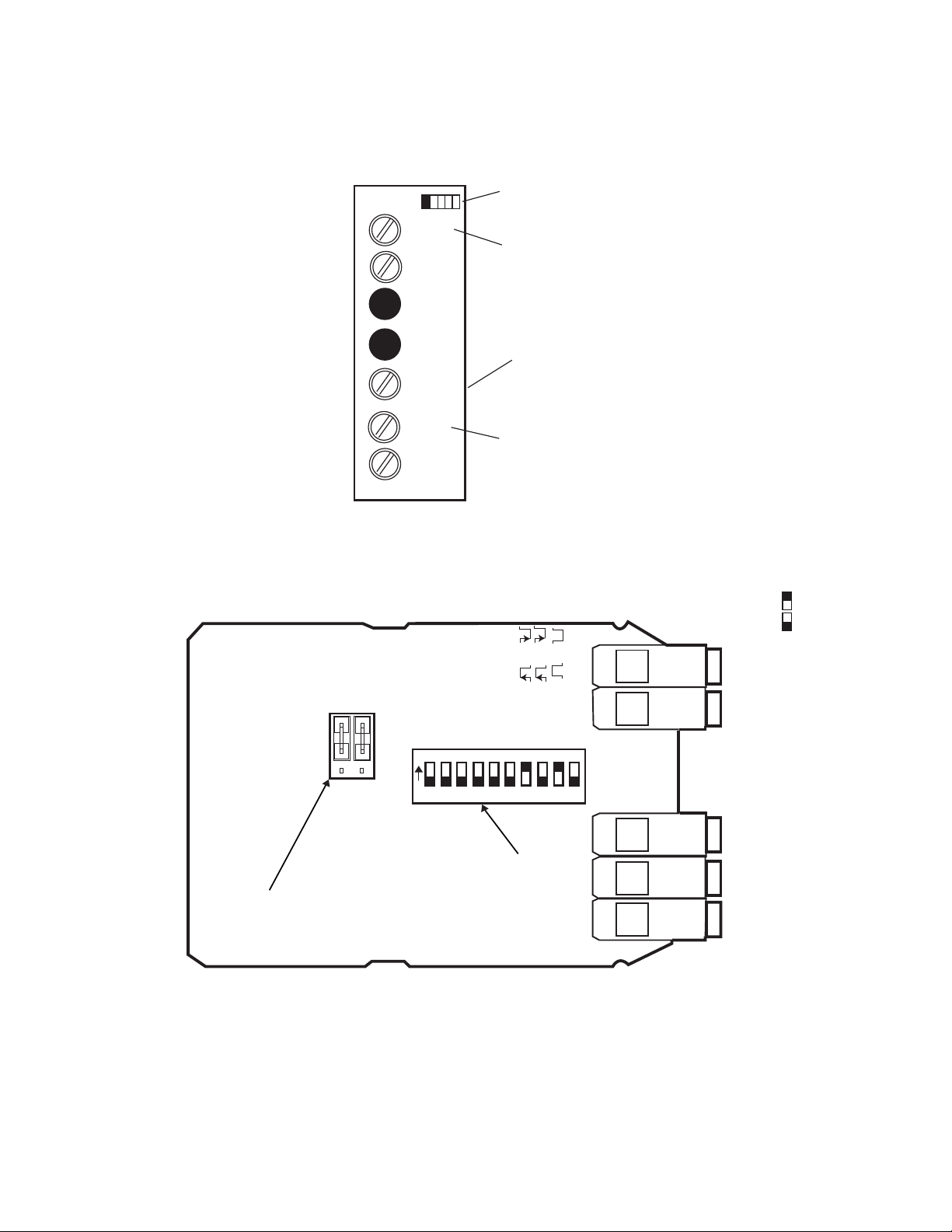
In both modes, the state of the User input signal can be selected as active high or active low. DIP switch SW1 configures the counter to match the specifications of the accompanying sensor. When shipped from the factory, the counter is set for X1 quadrature, as shown in Figure 10 and Table 3:
Denotes module
position 1 at rear
of counter
A INPUT
Primary Input
COMMON
USER
INPUT
or
Quadrature A
Display Hold
Freezes
Displayed value
Figure 9. Quadrature / Universal Input Module
1 23
JP2
Note: To Enable
standard count Mode
move both jumpers
down one pin
Quadrature
Count
Standard
Count
B INPUT
COMMON
INPUT
1 23
JP1
B Bias Off=Hi On=Lo
B Freq Off=Hi On=Lo
B Off= Sink On= Source
1 2 3 4 5 6 7 8 9 10
Secondary Input
or
Quadrature B
A Freq Off=Hi On=Lo
A Off= Sink On= Source
A Bias Off=Hi On=Lo
Quadrature Mode
(Factory Defualt)
B Edge Off= On=
SW1
Dip Switch:
Shown in
A Edge Off= On=
User pol Off= On=
Quadr Off=X4 On=X1
Dipswitch Legend
= ON
= OFF
Figure 10. Quadrature Input Module Default Settings
12
Find Quality Products Online at: [email protected]
www.GlobalTestSupply.com
Page 14

Table 3. Quadrature Module DIP Switch and Jumper Settings
JP1/2: Count Mode Selector
Jumpered 1-2 = Quadrature mode**
Jumpered 2-3 = Standard counter mode
SW1: 10 Position DIP Switch
* = Factory Default setting
1 B Channel Bias: OFF = Hi* VLT = 5.0V VUT = 7.0V (+/- 10%)
ON = Low VLT = 1.6V VUT = 3.6V (+/- 10%)
2 B Channel Frequency: OFF = Hi* (low pass filter disabled)
ON = Low (low pass filter enabled)
3 B Channel Sensor: OFF = Sinking* (internal pull-up enabled)
ON = Source (internal pull-down enabled)
4 A Channel Bias: OFF = Hi* VLT = 5.0 V VUT = 7.0V (+/- 10%)
ON = Low VLT = 1.6 V VUT = 3.6V (+/- 10%)
5 A Channel Frequency: OFF = Hi* (low pass filter disabled)
ON = Lo (low pass filter enabled)
6 A Channel Sensor Type: OFF = Sinking* (internal pull-up enabled)
ON = Source (internal pull-down enabled)
7 B Channel Count Edge: OFF = Rising (standard count mode only)
ON = Falling*
8 A Channel Count Edge: OFF = Rising (standard count mode only)
ON = Falling*
9 User Input Polarity: OFF = High/open circuit = Inhibit Count
ON* = Low/closed circuit = Inhibit Count
10 Quadrature Mode: OFF = X4 (quadrature mode only)
ON = X1*
13
Find Quality Products Online at: [email protected]
www.GlobalTestSupply.com
Page 15
2.6 Excitation Module
QUADRATURE
ENCODER
PHASE A-WHITE
PHASE B-GREEN
+
COMMON
(BLACK)
POSITIVE-RED
A INPUT
COMMON
USER
INPUT
B INPUT
COMMON
INPUT
QUADRATURE
INPUT CARD
ISO+12V
ISOCOM
EXCITATION
EXCITAT ION
CARD
+
__
---
_
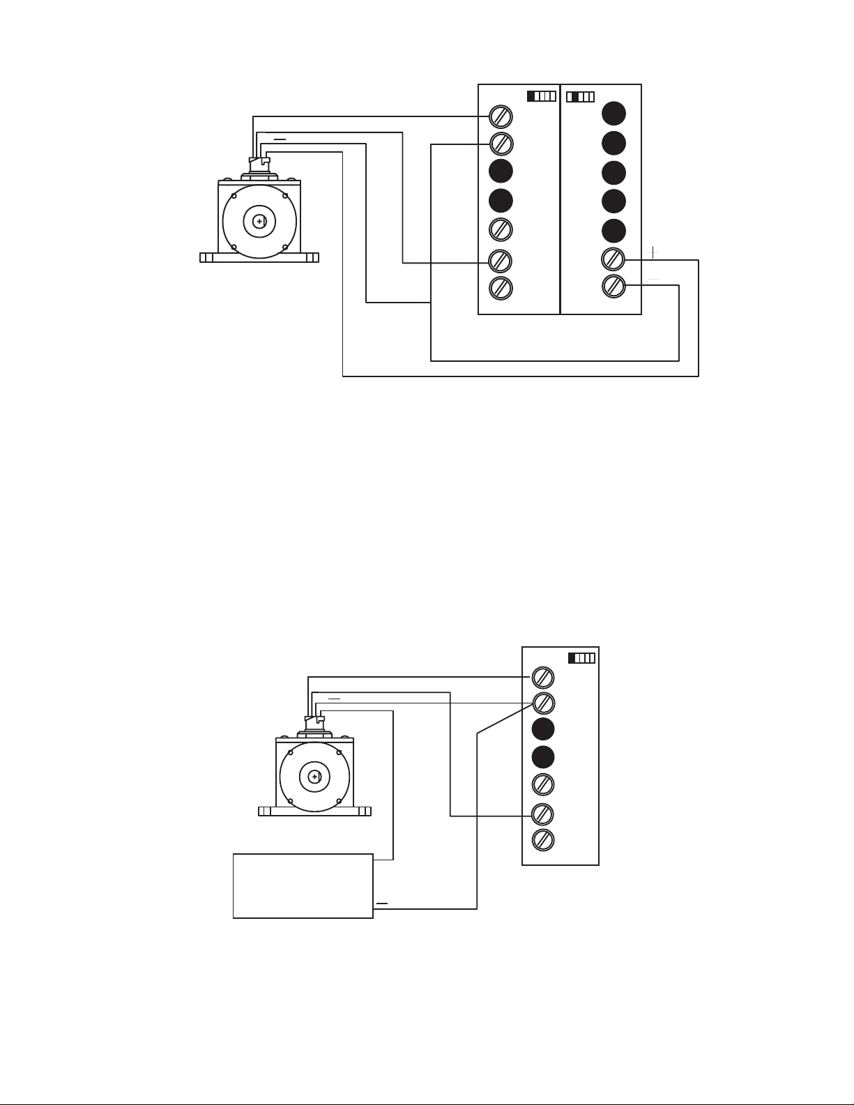
Figure 11. Wiring Encoder w/ Excitation Supply
12 VDC Excitation Module
The Excitation Module can supply 12 VDC at up to 100 mA for external sensors or encoders. This excitation is isolated from the counter internal logic supply. When using
sensors or encoders that do not have a signal return or imply a signal return that is in
common with the supply voltage, a common attachment that ties the excitation supply
to the logic input common may be required. Examples of this appear in figures 8, 8a,
11 and 12.
DENOTES MODULE POSTION 1
AT REAR OF COUNTER
MODEL S.E.
QUADRATURE
ENCODER
CHANNEL A-WHITE
CHANNEL B-GREEN
POSITIVE (RED)
EXTERNAL
POWER
SUPPLY
+
+
COMMON
(BLACK)
A INPUT
COMMON
USER
INPUT
B INPUT
COMMON
INPUT
QUADRATURE
INPUT CARD
Figure 12. Wiring Encoder with External Supply
14
Find Quality Products Online at: [email protected]
www.GlobalTestSupply.com
Page 16
Denotes module
position 2 at rear of
counter
ISO+12V
+
__
---
ISOCOM
EXCITAT ION
_
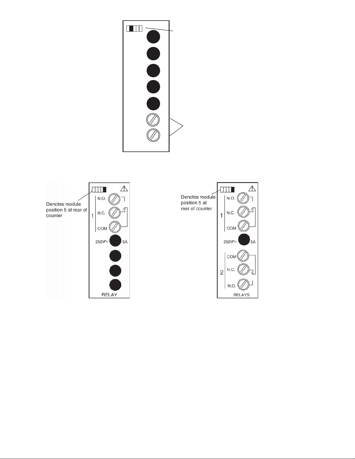
Figure 13. Excitation Module
2.7 Single and Dual Relay Modules
12 VDC, 100 mA max
Figure 14. Single Relay Figure 15. Dual Relay
The Single and Dual Relay modules can activate circuit loads of up to 5 amps at 250
VAC. A Form C configuration allows use of normally-open (NO) and normally-closed
(NC) circuit action.
Only the output 1 channel is implemented in the single relay module.
15
Find Quality Products Online at: [email protected]
www.GlobalTestSupply.com
Page 17
3 Display & Keypad Controls
3.1 Display
Output Status
Indicators
4 Button Keypad
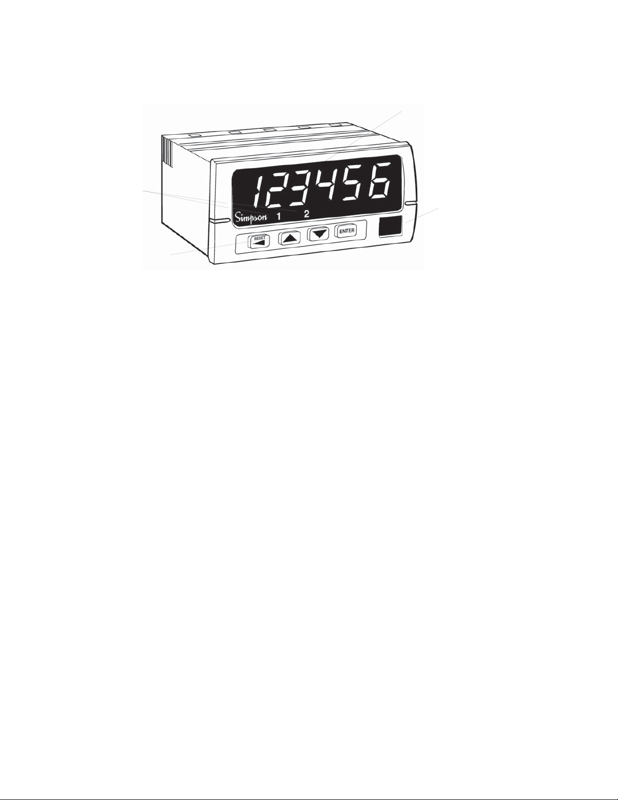
Figure 16. Display and Keypad Layout
• 6-digit 0.56” high red LED display.
Numeric & Message Display
Units Window
• 2 Output Status Indicators; “1” and “2.”
• Units Window for supplied label or legend.
• 4-Button keypad with tactile response.
16
Find Quality Products Online at: [email protected]
www.GlobalTestSupply.com
Page 18

3.2 Display Error Messages
Table 4. Display Error Messages
Display Description Action Required
PAdErr
The Keypad is disabled or a key is stuck in
the ON position
Cycle power to the
counter, if the error
remains, return
counter to factory for
repair.
999999 or
-99999
(Flashing)
E1
(Outputs
deactivate, count
stops)
E2
(Outputs
deactivate, count
stops)
E3
(Outputs
deactivate, count
stops)
The displayed count is too large for the
counter to displa
buffer is much larger than the display, the
counter will maintain accurate count and
control well beyond the display value.
Raw Count Overflow: The nu
pulses has exceeded the counter’s maximum
internal value (2,147,483,648 or
-2,147,483,648)
Math Overflow: A large scale factor in
combination with large raw count has
exceeded the counter's maximu
value (+2,147,483,648 or -2,147,483,648)
Watc
experience an orderly power-down. This can
h appen by exceed i n g the ma x i mum
allowable count speed for a sustained period
of time.
hdog Fau lt: Th e co unter di d n ot
y. Since the internal count
mber of count
m internal
Reset Counter
Reset Counter
Reset Counter
Reset Counter
17
Find Quality Products Online at: [email protected]
www.GlobalTestSupply.com
Page 19
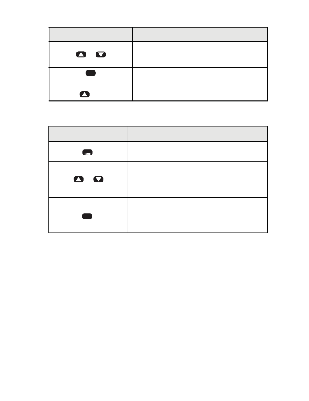
3.3 What the Keys Do in Display Mode
Key Keypad behavior
Allows quick access to all the set points. This
S or T
feature can be disabled by using a password (see
section 4.1).
Hold and
Press S
ENTER
Access the Programming Menu.
3.4 What the Keys Do in the Programming Mode
Key Keypad behavior
RESET
S orT
ENTER
Press and hold for four seconds to exi t the
programming mode.
The up and down keys navigate through the
available menu functions. The menu ‘wraps
around’ when the bottom or top of the menu is
reached.
1) Enter the current menu or parameter to
view/edit.
2) Write the change to the counter memor
move to the next function.
y and
18
Find Quality Products Online at: [email protected]
www.GlobalTestSupply.com
Page 20
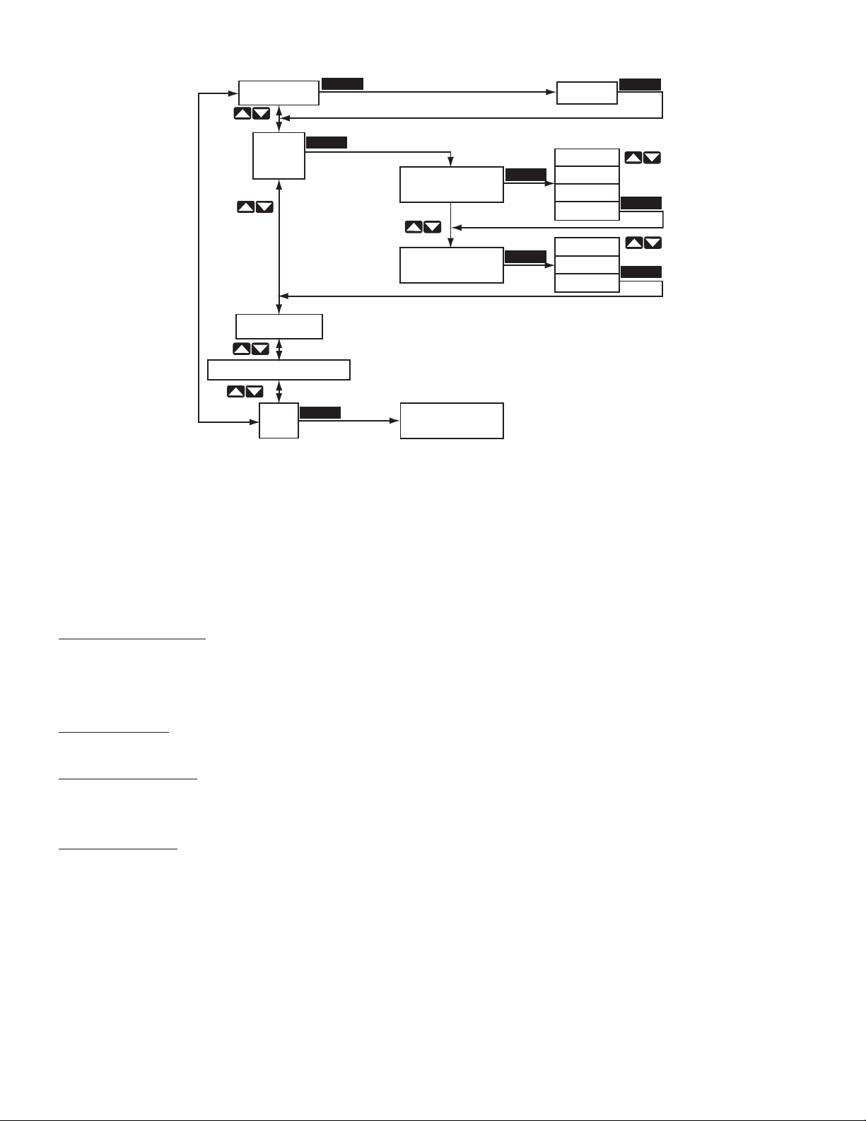
Setup Menu Function Menu Option Menu
CHPASS 000
INPUT
SETUP
COUNT SETUP
other setup menus
END
ENTER
ENTER
ENTER
A CHAN UP
B CHAN DOWN
Return to
Display Mode
ENTER
ENTER
Figure 17. Programming Menu Structure
000
up
down
quad
rquad
dir
up
down
ENTER
ENTER
ENTER
In the Programming Mode, the S661 will return to Display Mode automatically if a key
is not pressed within 120 seconds (2 minutes). The menu is comprised of three levels: Setup Menu, Function Menu and Option Edit Menu. Figure 17 illustrates the three
levels of the menu system.
Password Entry Entry (Pass) and changing of the password (Chpass) are similar to
editing a numerical parameter. See Numerical Value below. If the
password has been set to a value other than “000,” entry of the proper password is required to access the remainder of the menu.
Setup Menu At the first level of the menu, the arrow keys navigate up or down
through the available Menu selections.
Function Menu The second level of the menu contains the functions or software pa-
rameters that need to be configured for the counter to operate properly
Option Menu Contains either Choice Lists or Numerical Values for configuring the
counter
19
Find Quality Products Online at: [email protected]
www.GlobalTestSupply.com
Page 21
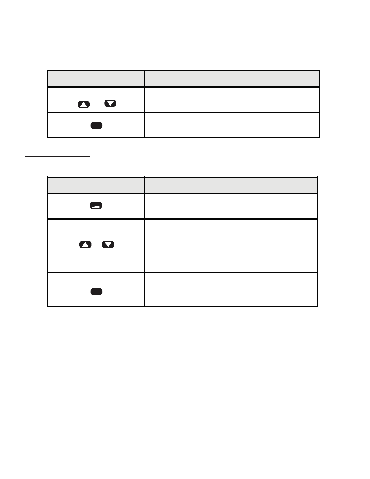
Choice List A Choice list allows one to select from a fixed number of options. A
Choice List is found in the Options section of the menu. This list is
made up of the available options for the function that is being edited. Example: Menu is Input Setup Menu, the Function is A Channel, the Choice List is up, down, quad and rquad (see Table 6).
Key Keypad behavior
The up and down keys scroll through the
ST
available choices in the Choice list.
ENTER
Saves the current choice as new parameter
setting and steps to next parameter or category.
Numerical Value A numerical entry allows the changing of set point values, scale
values, etc.
Key Keypad behavior
RESET
S or T
ENTER
Selects the next digit to the left of the current
flashing digit for editing.
The up and down keys increment or decrement
the flashing digit. Some parameters support
negative numbers. In these cases, the most
significant digit can be made negative by
incrementing it past "9."
Saves the values as the ne
w setting for the
function in memory and advances to the next
function of the menu automatically.
20
Find Quality Products Online at: [email protected]
www.GlobalTestSupply.com
Page 22
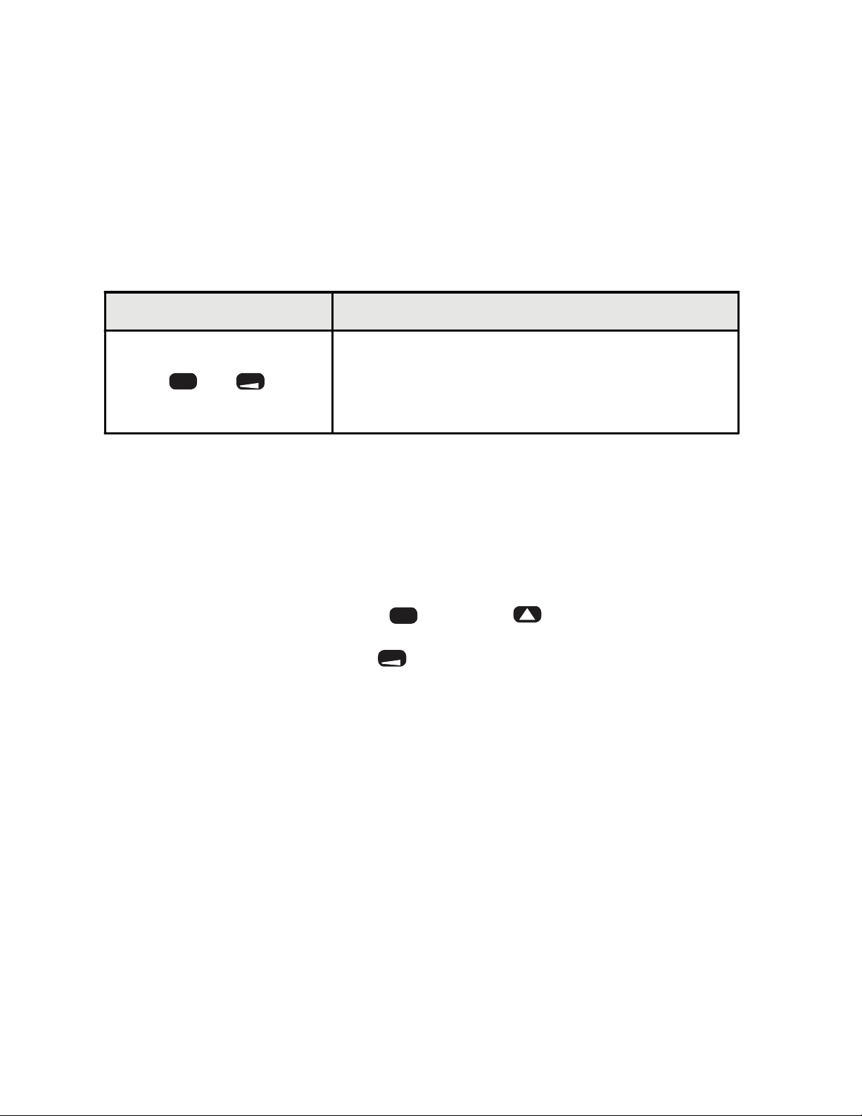
3.5 Special Start-Up Modes
There are two start-up modes for the S661 counter. The default start-up mode will be
used every time the counter is powered up by the user. There is one alternate startup mode that will allow the operator to return the counter software functions to factory
default settings.
The alternate start-up modes can only be accessed by pressing and holding certain
keys during the power up sequence.
• Press and hold both keys on the face of the counter
• Apply power while holding keys
Key Keypad behavior
Returns parameters to factory defaults. Resets
ENTER
and
RESET
password to 000, and all user scaling, operation
modes and set points to factory defaults. The
display will show freset.
4 Counter Operations and Parameters
This section details the programming options of the S661, presuming all defaults are in
place.
If you are already familiar with the S661 programming, see Appendix B for the Programming Quick Reference Guide.
To enter the Programming Mode, hold and press .
To return to the Display Mode, press and hold for four seconds.
ENTER
RESET
21
Find Quality Products Online at: [email protected]
www.GlobalTestSupply.com
Page 23
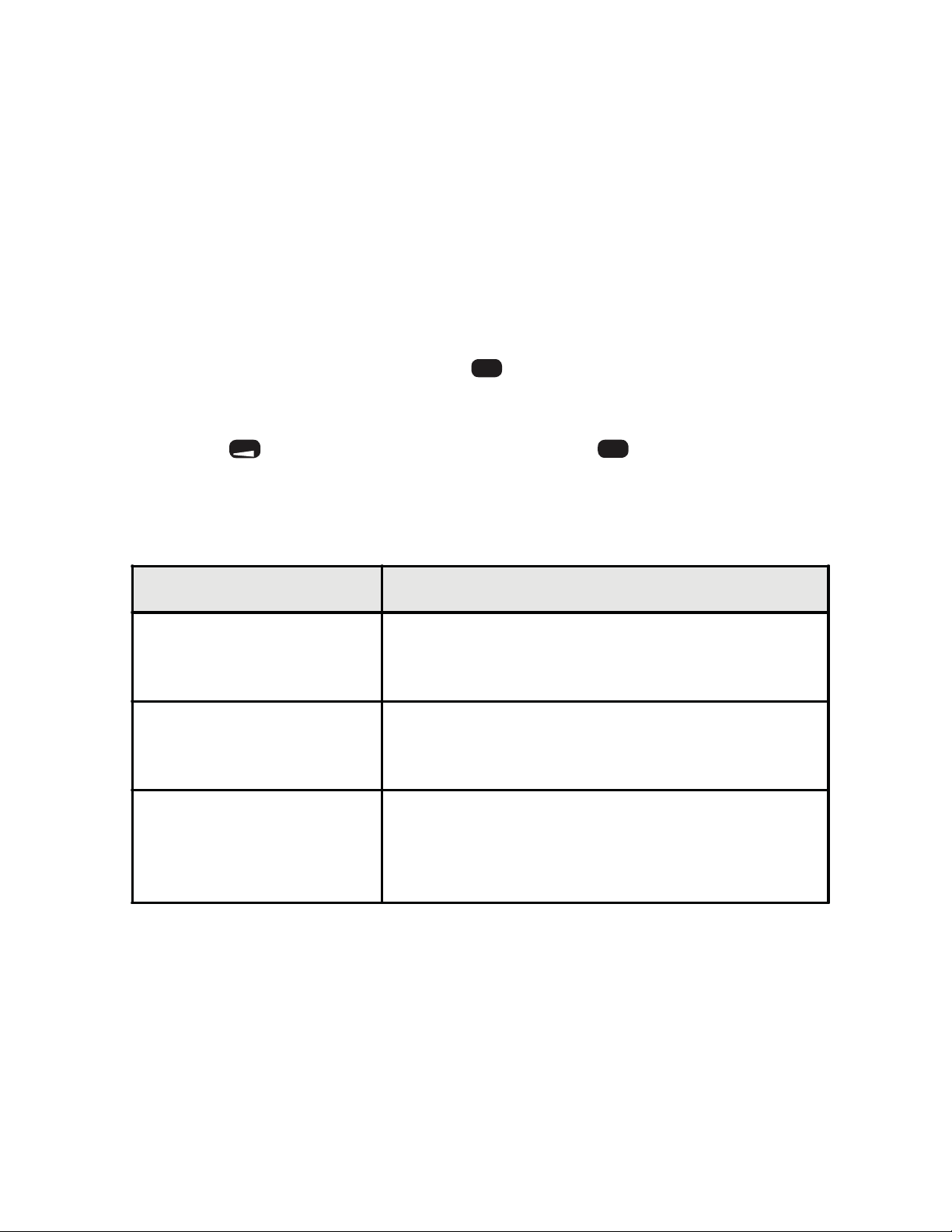
4.1 Password and Security Controls
The security feature helps prevent accidental changes to counter settings.
The password value determines the counter’s security level, as shown in Table 5.
If you have forgotten the password, see section 3.5; Special Start-Up Modes.
1) After entering the Programming Mode, the first field is Password.
a) If no password has been assigned, the counter will flash between chpass,
for “Change Password,” and the default value, 000.
b) To change the password, press when the display shows 000. Use the
ENTER
arrow keys to change the flashing digit to the desired number.
c)
Press to advance to the next digit. Press to accept the password to
RESET
ENTER
counter memory and press it again to advance to the next parameter, Input
Setup.
Table 5. Password Values
Password Value Level of Security
No Security - Default setting
000
001 - 099
100 - 999
Allows full access to the Programming Menu and
Quick Access to set points is enabled.
Fully secure
The Programming Menu is secured by password
and Q
uick Access to set points is disabled.
Quick Access Only
Programming Menu is secured by password,
Quick Access to set points via up and down keys
enab led.
22
Find Quality Products Online at: [email protected]
www.GlobalTestSupply.com
Page 24
2) If a password is already in the counter, the display will flash between pass, for
“Enter Password,” and the default value, 000.
a) When the display shows 000, press . Use the arrow keys to change the
flashing digit to the desired number. Press to advance to the next digit.
ENTER
RESET
b) Press to enter the password as shown. If an incorrect password is en-
ENTER
tered, access denied will flash on the display. Press an arrow key to return
to the pass display.
c) After entering the correct password, the counter will return to chpass.
Press to change password, or press the key to continue to the Input
ENTER
Setup menu category.
4.2 A/B Channel Options (Input Setup)
The next category in the Programming Mode is the “Input Setup.” Here you can adjust
the A and B channels to the appropriate count modes.
The A channel input may be selected as an Up, Down, Quadrature or Reverse
Quadrature* input.
As an Up channel, pulses applied to the A input are added to the display. In Down
mode, subtraction occurs. Note that when using Quadrature inputs, appropriate hardware (jumper) settings may be needed.
* The Reverse Quadrature input allows the user to reverse the count direction of the
encoder in software instead of having to rewire/remount the encoder.
Table 6. Channel A Selection
A CHAN Direction B CHAN
UP Up User defined
DOWN Down User defined
QUAD Up Not Available
R QUAD Down Not Available
23
Find Quality Products Online at: [email protected]
www.GlobalTestSupply.com
Page 25
1) To set the A Channel value:
a) When the display flashes input setup, press . The display will change to
ENTER
a chan.
b) Press again to proceed to the choice list. Scroll through up, down, quad,
ENTER
and r quad using the arrow keys.
c) When the selection is complete, press to accept the selection to counter
ENTER
memory, and press again to proceed to the next parameter, Chan B Mode.
The B channel may be set as Up, Down or Direction. In the direction mode, the B
channel is no longer a count source, but controls the count direction of the A channel
input. This state control works as an ‘exclusive-or’ with the channel A direction. Thus,
if B input is in the ‘Down’ state and A channel is set to Down, pulses at the A input will
increment count.
A Channel Setting State at B Input Resulting Count
UP UP UP
UP DOWN DOWN
DOWN UP DOWN
DOWN DOWN UP
Table 7. Count Behavior with B Channel Set as Direction Control
When A channel has been set to either Quadrature or Reverse Quadrature settings,
the B channel internally behaves as a direction control.
2) To set the B channel:
a) In the Input Setup area, after entering the A Chan value, the display will
flash between b chan and the counter’s default (dir).
b) When the display shows dir, press .
c) Use the arrow keys to change the value, then press to accept the selec-
ENTER
ENTER
tion and proceed to the next menu category, Count Setup.
NOTE: The B channel will not show in the menu when Quadrature or Reverse
Quadrature has been selected for the A Channel input.
24
Find Quality Products Online at: [email protected]
www.GlobalTestSupply.com
Page 26
4.3 Rate (Frequency) Scaling and Display (Rate Setup)
One of four rate modes may be selected to best accommodate input frequencies
ranging from 0.00278 Hz to 30 kHz. Select the rate mode according to Table 8.
Range
(implied scale)
mSec
(Hz ÷ 1000)
Sec
(Hz x 1)
Min
(Hz x 60)
Hr
(Hz x 3600)
Typical
Update
Period
1.0 sec 1 Hz 30 KHz
0.5 sec 2 Hz 30 KHz
3 sec
90 sec 40 Counts/Hr 3.0M Counts/Hr
Min. Input
Frequency
20
Counts/Min
Max. Input
Frequency
1.2M
Counts/Min
Comments / Typical Application
1/1000 Hz resolution / High precision
measurement of power line frequency
1 Hz resolution / Typical Setting for most
applications
Use when measuring ‘units per Minute'
Measures ‘units per Hour'. Also for very low
frequencies.
Table 8. Rate Mode Selection
Rate can also be displayed as a signed entity and will be negative according to the
direction state (see section 4.2). When B channel is configured for up or down count
input, the rate is the sum of the frequencies at A and B with the polarity of rate determined by the A channel up/down mode.
1) To set the rate mode, enter the Programming Mode and press until the rate
setup menu category is reached.
2) Press to continue to the parameter name rmmode. The display will flash be-
ENTER
tween rmmode and the default setting sec. When the display shows sec, press
.
ENTER
3) Use the arrow keys to scroll through the choices (mm sec, sec, mmin, hr). Press
when the correct mode is selected to accept mode and proceed to next pa-
ENTER
rameter, Scale.
Rate Scale
1) At scale, the display will flash between rscale and the default 01.0000, when the
display shows 01.0000, press .
2) Use the arrow keys to select the correct value for the flashing digit, press to
ENTER
RESET
advance to the next digit.
3) When the correct value is displayed, press to accept and proceed to next pa-
ENTER
rameter, Rate DP.
Rate Decimal Point Position
1) To set the Decimal Point position, enter the Programming Mode, and press
until the rate setup menu is reached.
2) Press to continue to the Parameter Name rat dp. The display will flash be-
tween rat dp and the default 000000. When the display shows 000000, press .
3) Use the arrow keys to scroll through the choices. Press when the correct deci-
ENTER
ENTER
ENTER
mal place is selected to accept value and proceed to the next parameter name,
Rate Offset.
25
Find Quality Products Online at: [email protected]
www.GlobalTestSupply.com
Page 27
Rate Offset
1) To set the Rate Offset, enter the Programming Mode, and press until the rate
setup menu is reached.
2) Press to continue to the Parameter Name offset. The display will flash between offset and the default 000000. When the display shows 000000, press .
3) Use the arrow keys to select the correct value for the flashing digit, press to
ENTER
ENTER
RESET
advance to the next digit.
3) When the correct value is displayed, press to accept and proceed to next
ENTER
menu category, Output 1 Mode.
Examples for Rate Mode, Rate Scale, Rate Decimal Point Position and Rate Offset are
on following pages:
Description Value Formula Value
Pulses per second
seen at input
Mode 2 = x1 sec/Hz sec Mode
User-entered
Multiplier
User-entered
additive value
Decimal P osition 0000.00 DP
10000 Input Frequency
.5000 Scale
100.00 Offset
Table 9. Rate Example
The input frequency can be linearly scaled using the Scaling Multiplier, Offset and
Decimal Point. The rate channel has an offset value as well. To illustrate, the following example will be used:
1) Multiply Input Frequency by implied Mode multiplier
10000 x 1= 10000
2) Multiply by user-specified Scale:
3) Discard all digits to right of decimal place:
(If number is larger than six digits, it will not fit in the display)
5000
4) Apply the user-specified DP location:
50.00
5) Add user-specified Offset location:
250.00 - 100.00 = 150.00
(That is what will be seen of the display)
The following notation may be used to describe this behavior:
Display = INT [Fint x Scale] DP + Offset
26
Find Quality Products Online at: [email protected]
www.GlobalTestSupply.com
Page 28

4.4 Output Control Modes
The S661 supports two independent output channels with four modes of operation:
disabled, timed, latched and boundary.
Output Type Description
Disabled Output
Timed Output
Latch Output
The output channel is inactive.
The timed mode activates an output when a set
point or ‘trigger’ condition is reached. Once active,
the output is held for a specified dela y period. The
delay may be between 0.01 and 599.99 seconds
The output w ill activate when the specified value is
encountered (SP1 for output 1, SP3 for output 2).
If a timing period is in progres s, a new trigger does
not occur. This is referred to as a nonretriggereable timer.
A RESET will cancel the timed out
The latch mode activates an output when a ‘trigger’
or set point is reached.
The output will activate when the value is
encountered (SP1 for output 1, SP3 for output 2).
Once activated, the output is held and can be
deactivated only when the speci
condition is met. The Latched Until conditions can
be seen in Tab l e 10.
put.
fied Latched Until
.
Boundary Output
The Boundary mode differs from the other output
types in that it allows the counter to have an output
activate/deactivate automatically within a specified
range.
Boundar y mode activat
count is between the specified low and high set
points (SP1/SP2 for output 1, SP3/SP4 for output
2.)
es an output when the
27
Find Quality Products Online at: [email protected]
www.GlobalTestSupply.com
Page 29
Latch Until Description
Reset
SP#
RstP os
A front panel or external reset event is required
to deactivate the output.
Output deactivated when set point is
encountered.
Output deactivated when reset position is
encountered.
Table 10. Latch Until
NOTE: The outputs for this counter activate regardless of count direction in
all count modes.
1) To set the Output Control modes, enter the Programming Mode, and press
until the oput 1 setup menu category is reached.
2) Press to continue to the Parameter Name mmode1. The display will flash
ENTER
between mmode1 and the default value of latch. When the display shows latch,
press
3) Use the arrow keys to select the correct mode. Press when the correct mode
ENTER
ENTER
is selected to accept value, and to the next parameter, Output 1 Bindings. Other
choices may appear, depending on which Output 1 Mode is selected. See Appendix B for which options correspond to which parameters.
4) Press until oput 2 setup is displayed to make similar selections for Output 2
ENTER
Mode.
5) When all selections are entered and accepted into counter memory, counter will
proceed to next menu category, Set Point Setup.
4.5 Set Point Parameters (Set Point Setup)
The S661 has four set point parameters and an Offset Value.
SP1 and SP2 are used only with Output 1, and SP3 and SP4 are used only with Output 2.
The SP1 and SP3 parameters are used as Latched or Timed “trigger” values. When a
Boundary Output is selected, SP1 and SP3 become the low boundary value.
The SP2 and SP4 parameters are used as high boundary value or ‘turn-off’ values
when used with other alarm types (i.e. latched until SP4).
The values for all set points are -99999 to 999999. The decimal point will appear according to the current decimal point setting.
28
Find Quality Products Online at: [email protected]
www.GlobalTestSupply.com
Page 30
Set Point Parameters
1) To set the Set Point parameters, enter the Programming Mode, and press until the setpnt setup menu category is reached.
2) Press to continue to the Parameter Name sp 1. The display will flash between
sp 1 and the default value of 000010. When the display shows 000010, press
3) Use the arrow keys to enter the correct value of the flashing digit. Use the
key to advance to the next digit. Press when the correct set point is select-
ENTER
ENTER
RESET
ENTER
ed to accept value and proceed to the next parameter, SP 2.
4) Repeat these steps for SP 2, SP 3, and SP 4. The counter will proceed to the
next menu category, Reset Setup.
4.6 Miscellaneous Controls
1) To access the Miscellaneous Controls, enter the Programming Mode, and press
until the reset setup menu category is reached.
2) Press to continue to the Parameter Name rstbtn. The display will flash between rstbtn and the default value of enable. When the display shows enable,
press
3) Use the arrow keys to select either Enable or Disable. Press when the correct mode is selected to accept selection.
4) The display will now show end. If you are finished programming the S661, press
If not, press the arrow keys to back up to the necessary parameter.
ENTER
ENTER
ENTER
ENTER
rStbtn
(Reset Button)
The Reset button Inhibit feature disables the front
panel reset button. This can be used to prevent
accidental resets. The external (rear panel)
hardware reset input is not affected by this setting.
29
Find Quality Products Online at: [email protected]
www.GlobalTestSupply.com
Page 31
Appendix A: Technical Specifications
A.1 Functional Specifications
Count modes supported
Count Inputs
Miscellaneous inputs
Maximum count rate
Min pulse width
Rate modes suported
Frequency accuracy
(instantaneous)
Frequency vs
temperature
Frequency vs time
(aging)
Count/Direction, Add-Add, Add-Subtract,
Subtract-Subtract, Quadrature, Batch, and Rate
2: Channel A (Primary) and Channel B
(Secondary/Dir control)
2: Reset (Alarm Reset) and User (Display Hold)
30 Khz (Standard and Quadrature X1 modes)
7.5 Khz (Quadrature X4 mode)
2 uS (
See Ta b l e 8
> ± 0.02% of reading
+ 0.0001% of reading per °C
± 0.002% of reading per year
Standard mode)
Display Digits
Display Decimal Point
Display LEDs
Display Range
Output channels
Output modes
Delay times
Output Response time
Multi-tasking Operatio n
6-digit, 7-segment with leading zero blanking
User-programmable
Red 0.56" (
- 99,999 to + 999,999 (Independent of decimal
position)
2, with front panel indicator for each
Disabled, Timed, Latching and Boundary
0.01 to 599.99 sec tol: -2.5 ms/+15ms
Within 10 ms of reading update (see rat
Count and output control maintained while in
Programming mode.
14.2mm), high efficiency
e modes)
30
Find Quality Products Online at: [email protected]
www.GlobalTestSupply.com
Page 32
A.2 Electrical, Environmental and Mechanical Specifications
Power Requirements
Power Consumption
Reset Input Signal
Storage Temperature
Operating Temperature
Relative Humidity
Bezel
Panel Cutout
Case Depth
Weight
AC Supply: 120 or 240 VAC, ±10%
3VA
Active Low: 0.2 VDC = active
-10 to 60°C
0 to 40°C
0 to 80% for temperatures less than 32°C,
decreasing linearly to 50% at 40°C. (Noncondensing)
3.93" x 2.04" x 0.52" (99.8 x 51.8 x 13.3mm)
3.62" x 1.77" (92 x 45 mm) 1/8 DIN
3.24" (82mm)
9.0 oz. (255.1g)
Standard input module
Input Channels
Count edge
Input Sources
Input Impedance
A & B channels
User Channel
Low pass filter
A, B and User
High to low transition (A and B channels)
Switch contact, CMOS or TTL logics, PNP or NPN
devices
Sinking: 10K, 5% Res. Pull-up to (9.0 - 16 VDC) ±10%
Sourcing: 5.1K, 5% Res. Pull-down to common
Input Thresholds
Low Bias mode:VLT = 1.6V ±10% VUT = 3.6V ±10%
High Bias mode:VLT = 5.0V ±10% VUT = 7.0V ±10%
VLT = 0.2V (min) VUT = 3.0V (max)
Frequency < 200Hz (0 to 10V input square wave at
50% duty cycle)
Max voltage
A, B and User channels 30VDC maximum sustained
31
Find Quality Products Online at: [email protected]
www.GlobalTestSupply.com
Page 33
Quadrature input module
Input
Channels
Input
Inversion
Operation
modes
Input
Sources
Input
Impedance
A & B
channels
A, B and User
User-selectable input polarity . A and B channel polarity
selective in standard mode only.
Standard, Quadrature X1 and Quadrature X4
Switch contact, CMOS or TTL logics, PNP or NPN
devices quadrature (single-ended) encoders
Sinking: 10K, 5% Res. Pull-up to (9.0 - 16 VDC) ±10%
Sourcing: 5.1K,
Low Bias mode:VLT = 1.6V ±10%VUT = 3.6V ±10%
High Bias mode:VLT = 5.0V ±10% VUT = 7.0V ±10%
5% Res. Pull-down to common
Input Thresholds
User Channel
Low pass
filter
Max voltage
VLT = 0.9V (min) VUT = 3.15V (max)
Frequency < 200Hz (0 to 10V input square wave at
50% dut
A, B and User channels 30VDC maximum sustained
y cycle)
Single / Dual Relay Modules
Contact Rating
Mechanical Life
5 Amps 250 VAC
1,000,000 cycles
Isolated 12V Excitation Module
Exitation Output
Exitation Isolation
100 mA at 12 VDC ±5%
1500 V
32
Find Quality Products Online at: [email protected]
www.GlobalTestSupply.com
Page 34
Appendix B: Programming Quick Reference
If you are unfamiliar with navigating menus in the S661 see section 3. Each parameter is listed in the order of appearance in the menu system. Refer to the paragraph
indicated in the Tech Note column for technical details on a particular parameter.
Tip: Photocopy these pages to mark settings on.
Menu
Category
Parameter
Name
PASS 000
ACCESS<—
CHPASS 000*
Choices /
Format
—>dEniEd
Description Tech
Password Entry and
Verification
Password Fail
Appears if incorrect
password entered
Password Change
Appears if correct
password entered
000 = Password
protection disabled
001-099 = Secures all
parameters
100-999 = Enables
SPs/ResPos access in
display mode
Note
4.1
4.1
4.1
* = factory default settings
33
Find Quality Products Online at: [email protected]
www.GlobalTestSupply.com
Page 35

Menu
Category
Parameter
Name
Choices /
Format
Description Tech
Note
inPut
SEtuP
rAtE
SEtuP
A CHAn uP*
doWn
quAd
r quAd
b CHAn dir*
uP
doWn
MmodE MmSEC*
SEC
Mmin
Hr
SCALE 00.0000*
Chan A Mode
Select count mode of A
channel.
Chan B Mode
Select count mode for B
channel.
Note: If A channel set to
Quad or Rquad, this item
is not accessible.
Rate Mode
Defines the prescaling
and sampling interval for
frequency compu ta tion
Scale
Set Display Value (Rate)
scaling multiplier.
Values: -9.9999 to 9.9999
4.2
4.2
4.3
4.
3
* = factory default settings
34
Find Quality Products Online at: [email protected]
www.GlobalTestSupply.com
Page 36

Menu
Category
Parameter
Name
Choices /
Format
Description Tech
Note
oPut 1
SEtuP
dP 000000*
000000.
00000.0
0000.00
000.000
00.0000
0.00000
oFFSEt 000000*
MmodE 1 diSAbL
timMEd
LAtCH*
bound
DP
Display Value 2 (Rate)
Decimal Point location.
Affects appearance of
Offset and Set Point
parameters.
Offset
Set Display Value 2
(Rate) scaling offset.
Values: -99999 to
999999. A decimal point
will appear according to
the user-programmedDP
position.
Output 1 Mode
Set the mode of
operation for Output 1.
Can be disabled, timed,
latched or boundary
mode.
4.3
4.3
4.4
* = factory default settings
35
Find Quality Products Online at: [email protected]
www.GlobalTestSupply.com
Page 37

Menu
Category
Parameter
Name
Choices /
Format
Description Tech
Note
oPut 2
SEtuP
SP1=Lo<—
—>SP2=hi
dELAY1 010.00*
MmodE2 diSAbL
timMEd
LAtCH*
bound
SP3=Lo<—
—>SP4=Hi
Output 1 Bindings
Reminder message
indicates which and how
the set points are used
for comparison.
Delay 1
Output 1 delay time.
Appears only if Output 1
mode set to timed.
Output 2 Mode
Set the mode of operation
for Output 2. Can be
disabled, timed, latched
or boundary m
ode.
Output 2 Bindings
Reminder message
indicates which and how
the set points are used
for comparison.
4.4
4.4
4.4
4.4
* = factory default settings
36
Find Quality Products Online at: [email protected]
www.GlobalTestSupply.com
Page 38

Menu
Category
Parameter
Name
Choices /
Format
Description
Tech
Note
SEtPnt
SEtuP
dELAY 2 010.00*
SP1 000010*
SP2 000020 *
Delay 2
Output 2 delay time.
Appears only if Output 2
mode set to timed.
SP1
Set point #1 Low. Values:
-99999 to 999999.
Decimal point will appear
according to the current
DP setting.
SP2
Set point #1 High. Values:
-99999 to 999999.
Decimal point will appear
according to the current
DP setting.
4.4
4.5
4.5
* = factory default settings
37
Find Quality Products Online at: [email protected]
www.GlobalTestSupply.com
Page 39

Menu
Category
Parameter
Name
Choices /
Format
Descriptio n Tech
Note
rESEt
SEtuP
END
SP3 000030*
SP4 000040*
rStbtn EnAbLE*
diSAbL
SP3
Set point #2 Low.
Values: -99999 to
999999. Decimal point
will appear according to
the current DP setting.
SP4
Set point #2 High.
Values: -99999 to
999999. Decimal point
will appear according to
the current DP setting.
Reset Button
Enable or disable front
panel reset button.
Exit Programming
Me
nu
4.5
4.5
4.6
* = factory default settings
38
Find Quality Products Online at: [email protected]
www.GlobalTestSupply.com
 Loading...