

Page 1

Mini-Max M240 Series Digital Panel Meter
Minimum Depth Indicator - Less Than 2.5” (60mm)
of Space Required Behind the Panel
Stackable Mounting Bracket Included for Easy
Installation
4 Digit, 0.56” (14.2mm) High, Red LED Display
Standard Screw Terminals for Easy Installation
User-Selectable Input Type (J or K T/C, RTD Pt100,
mV)
85-250VAC Power Supply
Brightness Adjustment
Temperature
Simpson’s Mini-Max Temperature Indicators provide high
quality, accuracy and reliability in a compact case. These
microprocessor-based units offer a 0.56” bright red, 4 digit
LED display for high visibility and is adjustable through 6
levels of brightness. The four input types and choice of °C
or °F display are jumper-selectable and can be changed with
no recalibration necessary.
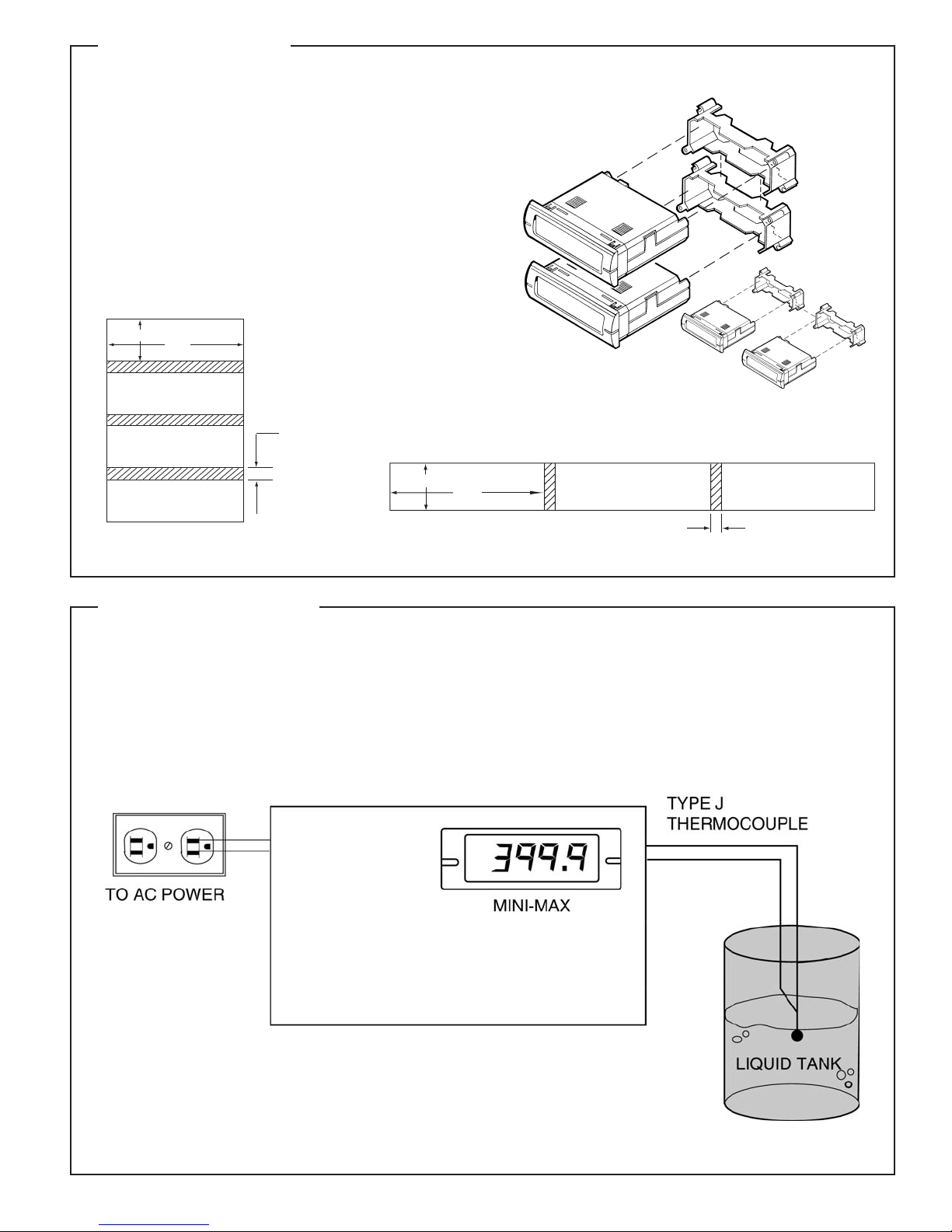
Installation and Panel Cutout
2.66”
.89"
2.71"
A unique mounting bracket is provided to allow for vertical
and horizontal stacking of multiple indicators. All Mini-Max
units feature a 3/64 DIN, high-impact plastic case. Screw
terminals are provided for easy wiring of the power supply
and input signal connections.
2.83"
0.16"
0.94"
2.36"
0.125" Max
Panel Thickness
.86"
Mounting Requirements
Insert the Mini-Max through the panel, and then slide the mounting bracket on to the Mini-Max. The mounting bracket allows Mini-Max units to
be stacked side-to-side or top-to-bottom and maintain the DIN standard
panel arrangements in 24mm by 72mm multiples. Panel cutout instructions for stacking multiple units are provided under “stacking features.”
Page 2

Specifications
THERMOCOUPLE
ENVIRONMENTAL
Operating Temperature:
0 to 55°C
Storage Temperature: -10 to 60°C
Relative Humidity: 0 to 85% non-condensing
Warmup time: Less than 20 minutes
ANALOG TO DIGITAL CONVERSION
Technique:
12 bit Successive Approximation (SAR)
Rate: 10 samples per second.
NOISE REJECTION
NMRR:
60dB, 50/60Hz
MECHANICAL
Bezel:
0.94” x 2.83”
(24mm x 72mm)
Depth: 2.36”(60mm)
Panel cutout: 0.89” x 2.71”
(22.2mm x 68mm)
Weight: 3.5oz (99.2g)
Case Material:
DISPLAY
Type:
7-segment red LED
Height: 0.56” (14.2mm)
Display resolution: 0.1º from -99.9º to 999.9º;
1.0º below -100º or above 1000º; 0.1mV for mV
indication
Open or faulty input connection: “----”
Uncalibrated instrument:
Display will flash continuously "INFO FAIL CALB
REQD" upon application of power.
Polarity:
Automatic, with “-” indication; “+” indication
implied
POWER REQUIREMENTS
AC Voltage:
85-250VAC @50-60Hz
Power Consumption: 2VA
Overrange indication (T/C or mV): The left-
most digit shows 1: "1" (other digits are blank)
Wiring Display
INPUTS
Thermocouple:
J, K
Millivolt:
±70mV (uncompensated for temperature)
Lead Resistance Effect: -13V/100 max.
RTD: Platinum 100 Ohm (.00385 alpha)
Lead Resistance Effect:
4-wire: -.26C/100V max.
2- and 3-wire: 1C/.29 max.
Temperature Coefficient: ±0.2C / C
Input Type Temperature Range Accuracy @258C
K T/C -100 to 1370C (0.1% rdg +1.5C)
-148 to 2498F (0.1% rdg +2.7F)
J T/C -100 to 1200C (0.1% rdg +1.5C)
-148 to 2192F (0.1% rdg +2.7F)
RTD Pt100 -100 to 850C (0.2% rdg +1.5C)
(4-wire) -148 to 1562F (0.2% rdg +2.7F)
mV -70 to 70mV (0.1% rdg +0.1mV)
(+0.1mV)
Input Impedance: 22M
TERMINAL
WHITE( )
TERMINAL
1 2
INPUT (-)
RED (+)
JUMPER (FOR 2 WIRE RTD ONLY)
INPUT (+)
RTD
1
234
5 6
BRIGHTNESS
(Short to Adjust)
RED (+) (3 WIRE AND 4 WIRE RTD'S)
WHITE ( )(4 WIRE RTD'S ONLY)
JUMPER FOR 2 AND 3 WIRE RTD
Input Selection
All Mini-Max Temperature Indicators are configured initially per the
customer specifications. Should the application change, the input type
can be changed as follows:
TERMINAL
7 8
LINE VOLTAGE
Power Supply: Connect the power supply to terminals #7 and #8 as
shown above.
Display Adjust: Connect a short between terminals 5 and 6 as
shown. Shorting these terminals will cause the display to continuously
cycle through 6 levels of brightness. When the desired brightness level
is attained, remove the short. The selected brightness level is stored in
memory and will be maintained. To readjust brightness level, repeat the
above procedure.
Input Type JU1 JU2 JU3 JU4
J T/C, C IN OUT OUT IN
J T/C, F IN IN OUT IN
K T/C, C IN OUT OUT OUT
K T/C, F IN IN OUT OUT
RTD Pt100, C OUT OUT IN OUT
RTD Pt100, F OUT IN IN OUT
mV IN OUT IN IN
See diagram at right for jumper locations.
NOTE: Recalibration is not required after an input change. If
desired, however, procedure is available from Technical Support.
Page 3
Stacking Features
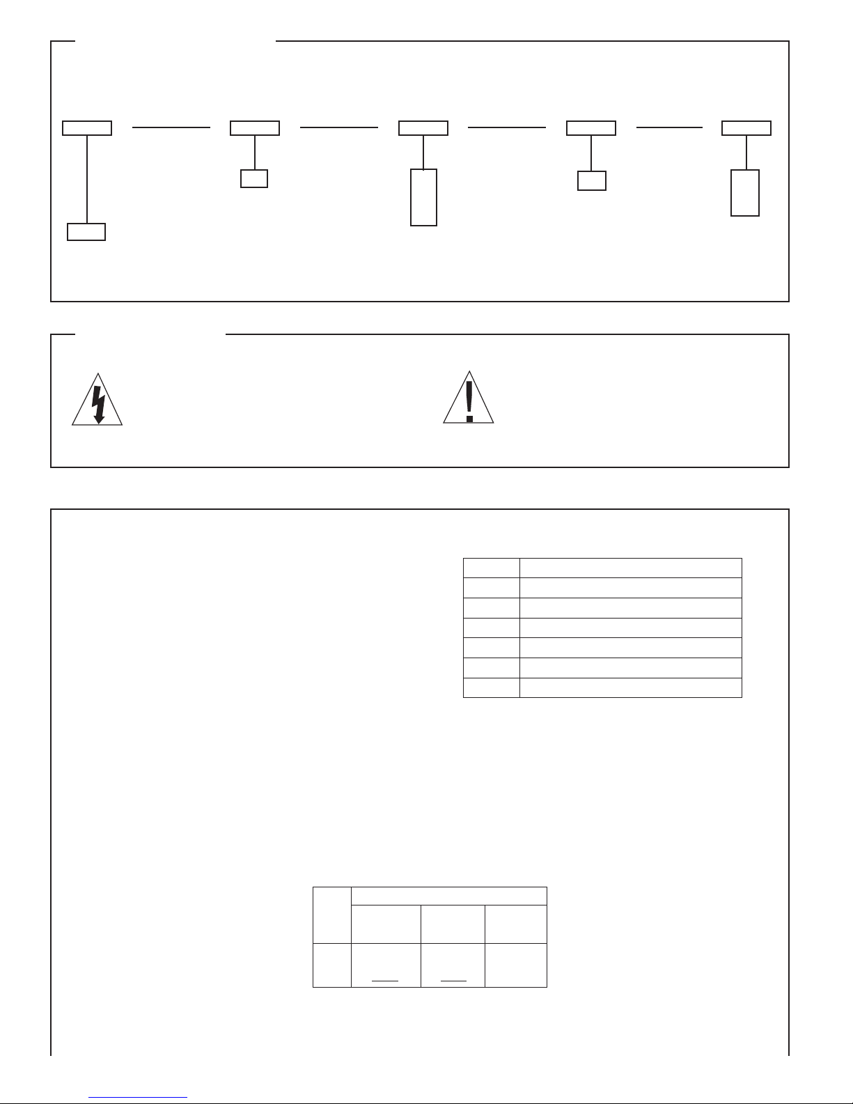
A plant engineer wants to install a meter in a panel to measure the
temperature of a nearby tank of liquid. The meter must accept a type
J thermocouple input and be capable of measuring at least 0-400˚F.
Depth behind the panel must also be kept to a minimum. A Temperature
Mini-Max M240-0-91-0-F will meet the engineer’s requirements.
Prior to connecting the thermocouple, make sure the jumpers are
positioned as follows:
- JU1, JU2, JU4 IN
- JU3 OUT
WIRING DIAGRAM
The mounting brackets, included with every Mini-Max, can be connected together. Multiple units can be mounted in a single opening,
allowing perfect alignment.
To punch one hole for multiple units, be sure to adjust the standard
panel cutout dimensions as shown here; otherwise the meters will not
fit properly in the hole.
Mounting multiple units is quick and easy. Install the first meter (bottom unit first if stacking vertically). Position the next mounting bracket
snugly against the first one, and slide the second meter into place.
Repeat for remaining units.
Vertical
Standard cutout
.88"
2.68"
.071"
Add to standard
when stacking
Horizontal
Standard cutout
.89"
2.71"
Vertical
Horizontal
Application Example
Add to standard when stacking
.16"
Page 4
Ordering Information
Your Mini-Max Temperature Indicator can be configured by making an entry for each box.
Basic Unit Power Supply Input Output Display*
J T/C
85-250 VAC
0
M240
4 Digit
Indicator
* Choose C or F for thermocouple or RTD. mVDC input displays mV reading only, not degrees.
91
92
93
94
K T/C
RTD Pt100
mV DC
None
0
C
F
0
Safety Symbols
C
F
mV
The CAUTION sign denotes a hazard. It calls attention
to an operating procedure, practice, or the like, which,
if not correctly adhered to could result in damage to or
destruction of part or all of the instrument.
Accessories
Simpson thermocouples are available in custom lengths per your
application. Calibration type, wire gauge, insulation type and length
are determined by your specifications, and entered into the following
ordering diagram.
Thermocouple Ordering Information
(Termination End: HJ-Beaded, CJ-Solid Bare Wire)
THERMOCOUPLE PROBES (QUICK DISCONNECT)
Simpson offers "Quick Disconnect" style thermocouples which include
a probe and an ANSI color-coded jack and plug. Each 12-inch thermocouple probe is compacted with MgO insulation, with 316 stainless steel
and 0.188 inch diameter outer sheath. Extra plugs and jacks are sold
separately. See the table below for ordering information.
THERMOCOUPLE PROBES (48 INCH LEAD WIRE)
Simpson's transition joint thermocouple probes are constructed with
MgO insulation. The probe includes 48" of Teflon® coated thermocouple wire and stripped leads.
The WARNING sign denotes a hazard. It calls attention to a procedure, practice, or the like, which, if not
correctly performed or adhered to, could result in
personal injury.
Thermocouple Ordering Information
(Termination End: HJ-Beaded, CJ-Solid Bare Wire)
Cat. No. Description
THJ105 T/C J, 24 Gauge, Fiber Glass Braid, 5 foot
THJ1015 T/C J, 24 Gauge, Fiber Glass Braid, 15 foot
THK105 T/C K, 24 Gauge, Fiber Glass Braid, 5 foot
THK1015 T/C K, 24 Gauge, Fiber Glass Braid, 15 foot
THJ035 T/C J, 20 Gauge, FEP Tefl on®, 5 foot
THJ315 T/C J, 20 Gauge, FEP Tefl on®, 15 foot
SIMPSON ELECTRIC COMPANY 520 Simpson Ave., Lac du Flambeau, WI 54538 • (715) 588-3311 • FAX (715) 588-3326
www.simpsonelectric.com Printed in U.S.A. Part No. 06-116176, Edition 13, 05/14
Catalog Numbers
ANSI Quick 48 Inch
Type Color Code Disconnect Lead Wire
J Black 21238 21242
K Yellow 21239 21243
RTD 21244
 Loading...