

Page 1
Getting Started
Landscape-Outdoor Lighting (Relay) Starter Kit
Model DKIT-05
Simply Automated Pre-Configured SimplySmart
Utilizes SimplySmart
No computer programming required!
Simple-n-easy, ready to use lighting control.
TM
technology to make installation a breeze.
TM
Series
Page 2

Getting Started DKIT-05
Landscape-Outdoor Lighting Kit
Simply Automated Pre-Configured SimplySmartTM Series
Utilizes SimplySmart
No computer programming required!
Simple-n-easy, ready to use lighting control.
IMPORTANT SAFETY INSTRUCTIONS
When using electrical products, basic safety precautions should always be followed, including the following:
1. READ AND FOLLOW ALL SAFETY INSTRUCTIONS.
2. Keep away from water. If product comes into contact with water or other liquid, disconnect immediately.
3. Never use products that have been dropped or damaged.
4. Do not use this product outdoors, unless protected by a weatherproof enclosure.
5. Do not use this product for other than its intended use.
6. Do not connect multiple loads that, when combined, exceed the maximum load rating of the product.
7. To avoid risk of fire, burns, personal injury and electric shock, install this product out of reach of small children.
8. Do not install in areas that can exceed 120°F (e.g., in an attic).
9. Do not cover the product with any material when in use.
10. This product uses polarized plugs and sockets (one blade is wider than the other) to reduce the risk of electric shock. These plugs and
sockets fit only one way. If they do not fit, consult a technician. Do not use with an extension cord unless plugs can be fully inserted. Do
not alter plugs.
11. SAVE THESE INSTRUCTIONS.
TM
technology to make installation a breeze.
DKIT-05 Outdoor-Landscape Relay Starter Kit
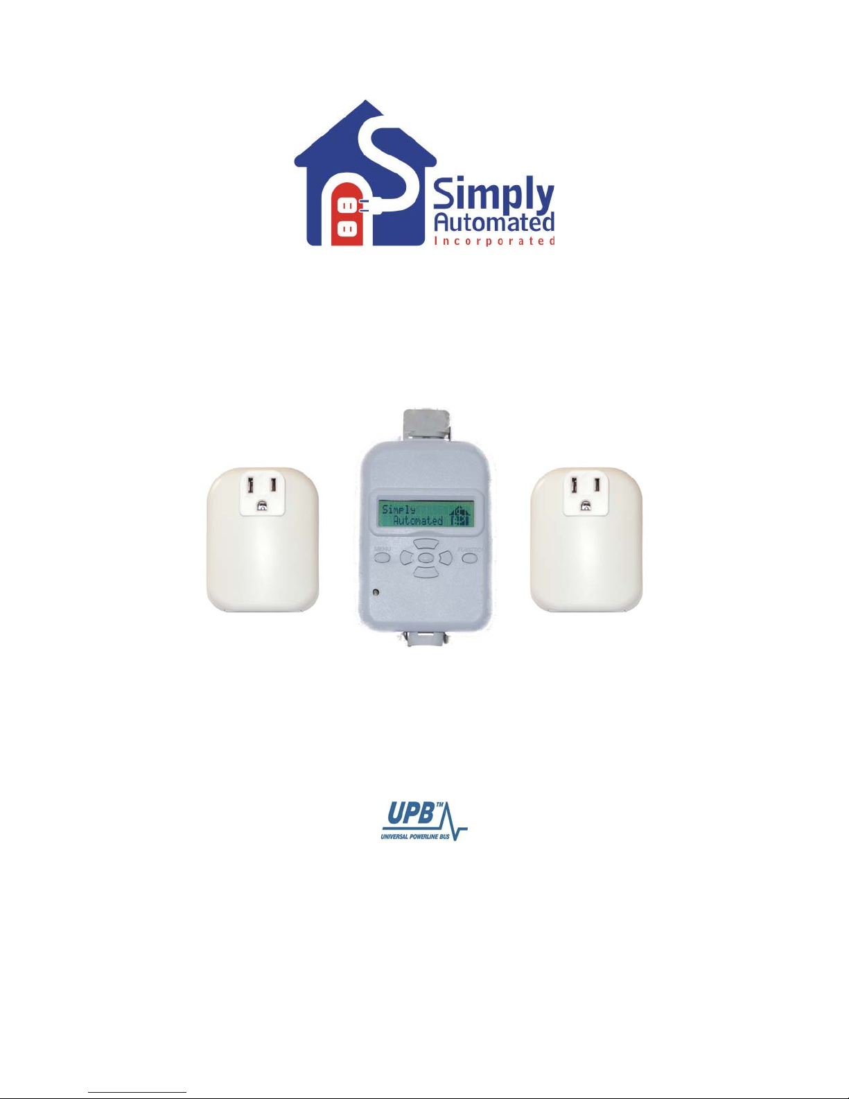
Includes 2 Appliance (relay) Modules and 1 Scheduler-Timer Controller
Getting Started
Section 1: Very Important Pre-Installation Notes
• Your home should be no more than 2500 square feet and have only one breaker panel. A phase coupler is
required in some home installations; especially homes > 2500 square feet or homes with more than 1
breaker panel. See Section 6 for more information.
• Not intended for use in multi-dwelling (condo, apartment) buildings with 3-p hase power.
• Do not reset to factory default configuration, pre-configured settings will be lost.
UPStart software and a computer interface module or Scheduler-Timer can be used with a PC for
•
customizing pre-configured units and checking performance.
Section 2: Installation of Appliance (relay) Modules and Scheduler-Timer Controller
Find a convenient location you would like to use for the Scheduler-Timer (e.g. outlet in garage, office, kitchen or
closet) and plug in the Scheduler-Timer controller. Locate 2 electrical loads you would like to turn ON/OFF with
the relay modules, such as outdoor low-voltage lighting transformers, appliances, pump/motors or lights. Plug a
relay module into a wall outlet (or the outlet used for a timer in the outdoor lighting transformer). Next, the power
cord of the electrical load (transformer) to be controlled plugs into the socket on the
module. Note, the convenience outlet on the
front of the appliance module is always ON and is not ON/OFF
bottom of the appliance
controlled. If there is an ON/OFF switch on the plugged in electrical load, then turn the load switch ON. Repeat
this process for second relay module. You're done with the installation process! If necessa ry, please refer to the
User Guide enclosed in the Appliance Modules product box or see
http://www.simply-
automated.com/documents/452-0013-0101_RevF_UMA_UserGuide_090512.pdf.
Simply Automated, Incorporated
6108 Avenida Encinas, Suite B, Carlsbad, CA 92011 USA
Technical Support: www.simply-automated.com
452-0001-0005WEB Rev. B Revised: September 22, 2011
2
or 800-630-9234
Page 3
Getting Started DKIT-05
Landscape-Outdoor Lighting Kit
Important Note: Incase power is lost the Scheduler-Timer stores a charge to power the internal clock.
Plugging the scheduler into power for 24 hours or more will fully charge the unit and ensure clock
functionality for more than 5 days without power. If power is lost or the scheduler is unplugged for more
than 5 days, the previously programmed events will not be lost. Events and settings are stored in nonvolatile FLASH memory for up to 10 years without power. No batteries are used or required.
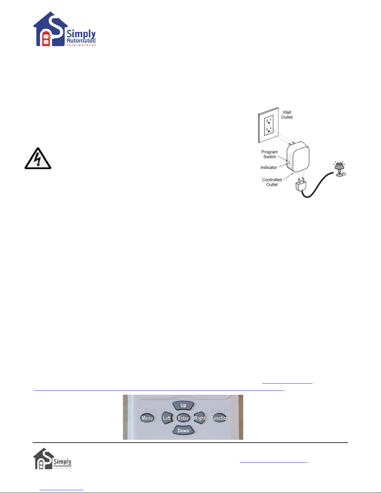
Test Appliance Module and Load. Manually turn ON/OFF appliance (relay) modules using the program switch
(see illustration):
•
Go to the location of the first relay module #18. Using a non-metallic
toothpick press and hold the program switch until the indicator flashes red.
CAUTION: When pressing the program switch do not insert any metal object
(paperclip) into the module while it is connected to power.
•
While the indicator is flashing red, press the program button once
to toggle ON and a second time to toggle OFF. Repeat as desired to
ensure the load is connected and functioning properly. The connected
electrical load should turn ON and OFF as the program button is toggled.
When done testing the relay module and electrical load, press and hold the
•
program button until the indicator stops flashing (or wait 5 minutes and the indicator will time out and stop
flashing). The relay module and load are now tested and ready to be controlled by the scheduler, or other
pre-configured scene controllers.
•
Go to the location of the second relay module, labeled #19, and repeat the steps above to ensure the relay
module and the connection to the transformer load are correct and functioning properly.
Helpful Hint: If the electrical load does not turn ON/OFF, make sure it is plugged into the bottom of the appliance
module (not the front). Make sure the electrical load’s ON/OFF switch is turned ON.
Important Note: Each appliance relay module has a unique ID number. You can find the ID number on
the back of each module. One of the appliance modules for the Landscape-Outdoor Relay Starter Ki t
(DKIT-05) will have ID #18 and the other will have ID #19. This is important information to note as it
relates to operation with the Scheduler-Timer accessory.
Section 3: Setting Time, Location and Network ID
The Scheduler-Timer is a powerful event processor. Once the Time, Location and Network ID are set scheduled
events can be referenced to sunrise (dawn) and sunset (dusk). This allows control of lighting without the need to
adjust settings for seasonal changes. The scheduler has four Schedule Modes: OFF, RUN, VAC (vacation) and
ALT (alternate vacation). Vacation modes are generally related to indoor lighting and creating scenes with
variable randomness (e.g. ON/OFF time +/- 1 to 60 minutes). This randomness is designed to give a home the
‘lived in look’ when set in either of the two vacation modes. For more information on vacation modes please refer
to the User Guide enclosed in the Scheduler-Timer product box or find it on line at:
automated.com/documents/452-0031-0101_RevB-WEB_UCS-01_User_Guide_090824.pdf.
Before setting events the scheduler needs to have the time,
date, day of the week and Network ID# set. Seven navigation
buttons are used to choose menu items, change values and
enter settings (see illustration).
http://www.simply-
3
Simply Automated, Incorporated
6108 Avenida Encinas, Suite B, Carlsbad, CA 92011 USA
Technical Support: www.simply-automated.com
452-0001-0005WEB Rev. B Revised: September 22, 2011
or 800-630-9234
Page 4
Getting Started DKIT-05
Landscape-Outdoor Lighting Kit
Section 3.a. Setting the Time, Date, Day and Schedule Mode
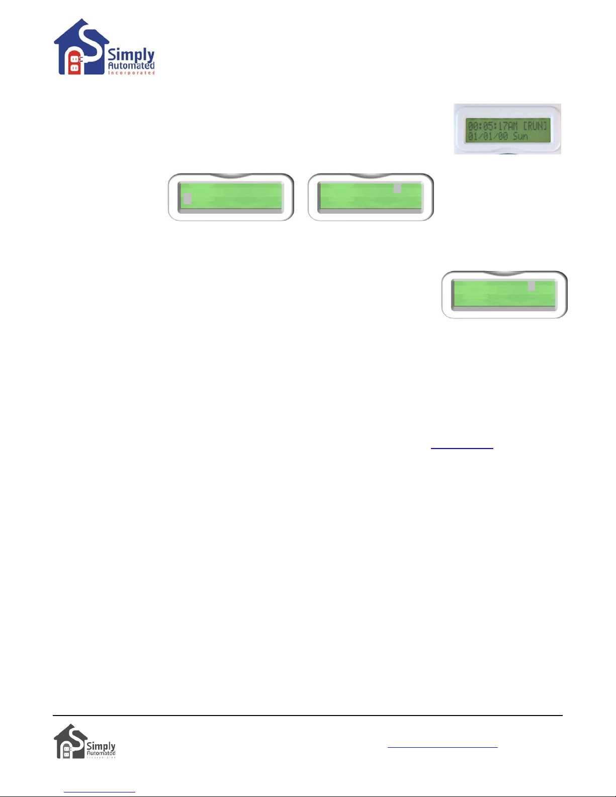
Set Time. With the scheduler plugged into power, the Idle screen should be displayed:
• Press the MENU button, then press the Down button one time to select “2) Set
Time” with the cursor. Idle screen
Menu screen Set Time screen
1)Set Events
2)Set Time
03: 50PM [RUN]
05/09/06 Tue
•
Press the Enter button to view the Set Time screen.
Helpful Hint: To edit time, date and other fields, move the cursor with the Right and Left buttons to select the fieldcharacter to be changed. Use the Up and Down buttons to change the character.
• See the cursor blinking on the ‘R’ of RUN in the Schedule Mode field. Pressing
the Up or Down buttons will scroll through RUN, OFF, VAC (vacation mode)
03: 50PM [RUN]
05/09/06 Tue
and ALT (alternate vacation mode).
• If necessary move the cursor with the Right (or Left) button to the Schedule Mode field and use the Up and
Down buttons to select RUN mode. This will ensure that the scheduler is ON and will process normal runtime
‘Run’ (R) events.
• Move the cursor with the Right (or Left) button to the Date field, then use the Up or Down buttons to set
today’s date; month / day / year format.
• Move the cursor with the Right (or Left) button to the Day of the Week field and use the Up or Down buttons
to set the day of the week.
• Find an accurate clock (e.g. cell phone, time referenced on a TV station or go to www.time.gov) and read the
time. Next move the cursor with the Right (or Left) button to the time field. Use the Up and Down buttons
enter the current time, hours then minutes, and AM or PM.
• Press the Enter button to save the time, date, day, and schedule mode. The scheduler’s clock will start at
the new time. You are done setting the time on your Scheduler-Timer.
Helpful Hint: Pressing the Enter button saves the changes made. Pressing Menu button will exit back to the
Menu without saving changes.
Helpful Hint: Pressing the Enter button to save the time restarts the scheduler’s clock at the new time. The
display will show the Idle screen and the time you set. You’ll see the seconds accumulating from 00 through 59.
To set and start the scheduler’s time most accurately, using your clock sou rce (e.g. cell ph one) set the time on the
scheduler 1 minute ahead of the time on your clock source. Then when the minute changes on the clock source,
press Enter
on the scheduler. You should be able to set the time of the scheduler within a few seconds of the
clock source.
Helpful Hint: When Set Time is selected from the menu, the cursor appears in the Schedule Mode field. This was
intentional as it makes changing from RUN to VAC (vacation) quick and easy. Far easier than walking the hou se
to plug in and set individual timers. To change Schedule Mode from RUN to VAC (vacation) simply press:
• Menu
• Down (to Set Time), then Enter
• Down (to VAC), then Enter
Simply Automated, Incorporated
6108 Avenida Encinas, Suite B, Carlsbad, CA 92011 USA
Technical Support: www.simply-automated.com
452-0001-0005WEB Rev. B Revised: September 22, 2011
or 800-630-9234
4
Page 5
Getting Started DKIT-05
Landscape-Outdoor Lighting Kit
Section 3.b. Setting the Location (Zip Code or Longitude & Latitude)
Setting the location allows the scheduler timer to calculate sunrise (dawn) and sunset
(dusk), as well as daylight savings time.
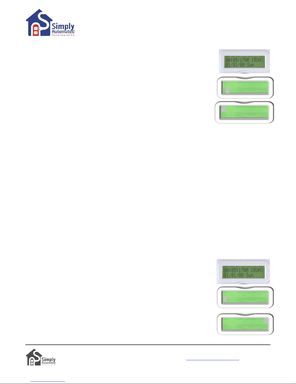
Set Location. With the scheduler plugged into power, the Idle screen should be
displayed:
• Press the MENU button, and then press the Down button two times to select “3)
Set Location” with the cursor.
2)Set Time
3)Set Loca ti on
• Press the Enter button, to view the Set Location sub-menu.
• Press the Enter button, to select “1) ZIP Code OR”. Note, Longitude and
1)ZIP Code OR
2)Long&Latitude
Latitude can still be entered by selecting Zip Code.
• Press Up (or Down) buttons to change characters of your zip code. Press Right (or Left) buttons to move the
cursor to the next digit.
• When your zip code is input correctly press the Enter button. The scheduler will display the central
longitude and latitude for your zip code. Also the Day Light Savings (DLS = Y) function will be displayed as
enabled (Y = yes enabled; N = not enabled) and Time Zone (TZ= Hours from Greenwich Mea n Time).
• Press the Enter button and the scheduler will calculate sunrise (dawn) and sunset (dusk) for your location.
• Press the Enter button again to save these settings and return to the main Menu. You are done setting the
Location.
Helpful Hint: Pressing the Enter button saves the changes made. Pressing Menu button will exit back to the
Menu without saving changes.
Helpful Hint: It is recommended to only enter the Zip Code and not change Longitude and Latitude unless your
zip code is outside of the United States. Setting event times based on dawn and dusk are adjustable (e.g. Dusk
+/- 15 minutes, up to 1 hour), so any minor differences in Longitude and Latitude can be made by offsetting the
event ON/OFF time to your preference.
Section 3.c. Setting the Network Identification Number
All the modules and dimmers in the Pre-Configured SimplySmart™ Series were set to network ID #250. The
Scheduler-Timer must be set to a network ID # of 250 otherwise the events will not function.
Set Network. With the scheduler plugged into power, the Idle screen should be
displayed:
• Press the MENU button, then press the Down button five times to select “6) Set
Network” with the cursor.
5)Set Randomness
6)Set Network
• Press the Enter button, then press and hold the Up button to scroll up to 250.
Pressing and holding the Up button will speed scrolling to make this selection
faster.
Select NetID=250
• When the Network ID has reached 250 release the Up button. Press the Enter
button to save the Network ID number. You are done setting the Network ID.
Simply Automated, Incorporated
6108 Avenida Encinas, Suite B, Carlsbad, CA 92011 USA
Technical Support: www.simply-automated.com
452-0001-0005WEB Rev. B Revised: September 22, 2011
or 800-630-9234
5
Page 6
Getting Started DKIT-05
Landscape-Outdoor Lighting Kit
Section 4: Setting and Testing Events
There are 99 available Events that can be set for any and all days of the week. Each event has an ON time and
an OFF time. Each event can control one module or dimmer at a time or a group (SCENE) of modules and
dimmers at the same time. Each event has a mode (i.e. Event Mode) that determines which type of Schedule
Mode runs the event. The three Event Modes are: (R) event enabled in the schedule modes Run and Vacation,
(r) event disabled in all modes, and (V) event enabled in vacation and alternate vacation schedule modes only.
For more information refer to the User Guide enclosed in the Scheduler-Timer product box or find it on line at:
http://www.simply-automated.com/documents/452-0031-0101_RevB-WEB_UCS-01_User_Guide_090824.pdf.
Important Note: Each relay module (or dimmer) in the Pre-Configured SimplySmart™ Series has a unique
ID number. You can find the ID number on the back of each plug-in module (or on the front of each
dimmer). The relay modules in the Relay Starter Kit (DKIT-05) have ID #018 and #019. This is important
information to note as it relates to operation with the Scheduler-Timer. In addition, there are preconfigured lighting SCENE numbers used with the relay modules and other modules and dimmers in the
Pre-Configured SimplySmart™ Series. Scene Link ID #019 controls both relay modules and dimmers.
Section 4.a. Setting Event 01) for Relay Module #018
In this example the first relay module #18 (as labeled on the back of the unit) will be set to turn ON at dusk and
OFF at 11PM, when the scheduler is in the regular runtime (RUN) schedule mode. If you would like to set
ON/OFF times other than Dusk/11PM feel free to do so.
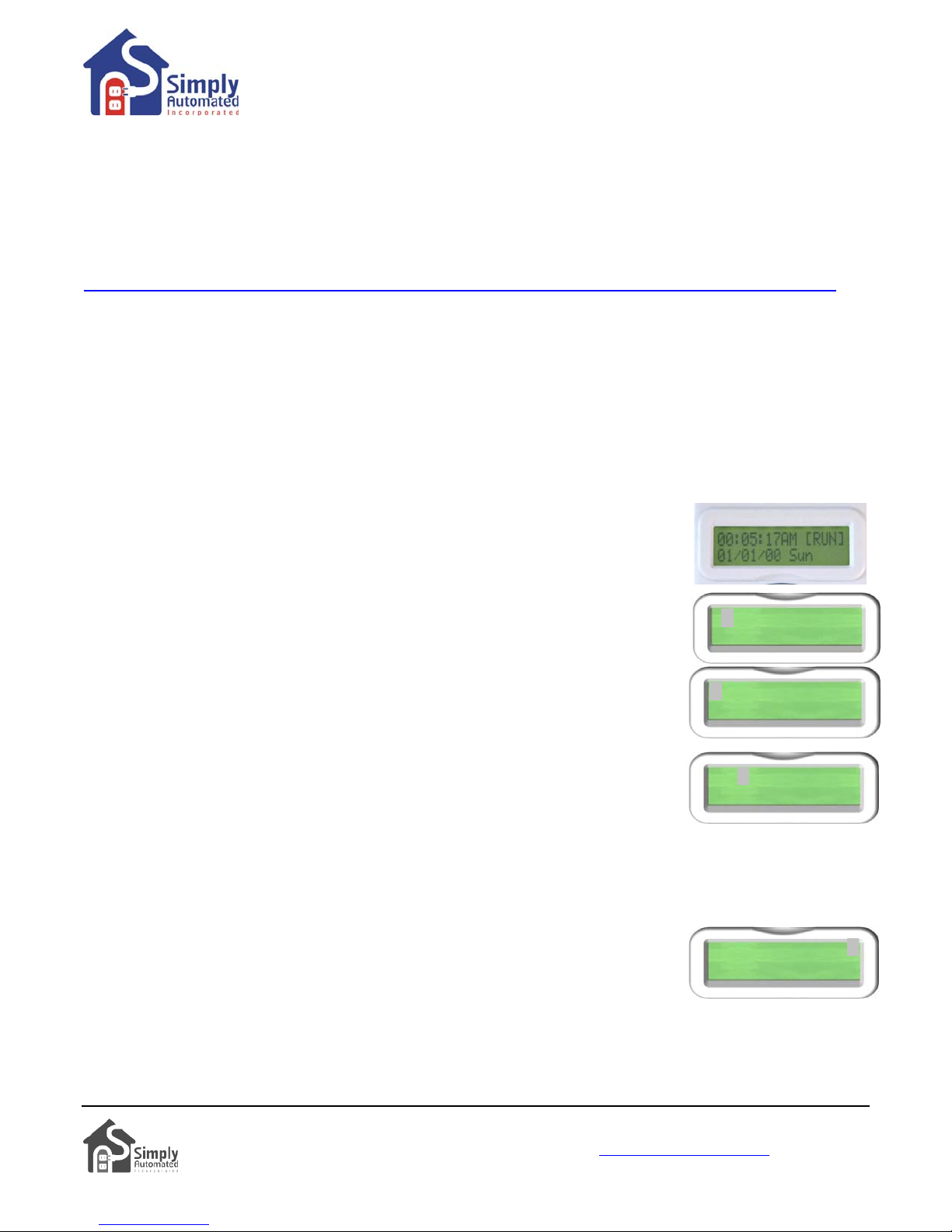
Set Event 01). With the scheduler plugged into power, the Idle screen should be
displayed:
• Press the MENU button. The cursor will highlight the first menu item “1) Set
Events”, press the Enter button.
• The scheduler will show the first event “01)”. When the cursor is in this event
1)Set Events
2)Set Time
number field, pressing the Up or Down buttons will scroll up to the previous event
or down to the next event.
01)---SMTWTFS R
12:00A 12:00A LA
• With the cursor highlighting the event number “01)”, press the Right button to
move the cursor over to the Device ID number field. Press the Up button to scroll
up to the relay modules’ device number “018”. If you pass 018, press the Down
button to go back, so “018” is in the device ID field.
01)018 SMTWTFS R
12:00A 12:00A LA
• Press the Right button to move the cursor over to the days of the week field.
Pressing the Up or Down button on any of the days of the week will change the
capital letter to a lower case letter. Capital letter indicates an ON day; lower case indicates an OFF day for
this first “01)” event. Leave all the initials of the days of the week (Sunday through Saturday) capitalized if
you want the event to run every day; or change any day to a lower case if you do not want this event to run on
that day.
• Press the Right button to move the cursor over to the Event Mode field. Pressing
the Up or Down button will scroll through the three event modes: “R” (Run) event
is active in the normal RUN schedule mode, “r” (off) event is disabled for all
01)018 SMTWTFS R
12:00A 12:00A LA
schedule modes, and “V” (vacation) event is active in the “VAC” (vacation) and
“ALT” (alternate vacation) schedule modes.
• Using the Up or Down buttons set the event mode to “R” run, so the event will be active in the normal runtime
schedule mode.
Simply Automated, Incorporated
6108 Avenida Encinas, Suite B, Carlsbad, CA 92011 USA
Technical Support: www.simply-automated.com
452-0001-0005WEB Rev. B Revised: September 22, 2011
or 800-630-9234
6
Page 7
Getting Started DKIT-05
Landscape-Outdoor Lighting Kit
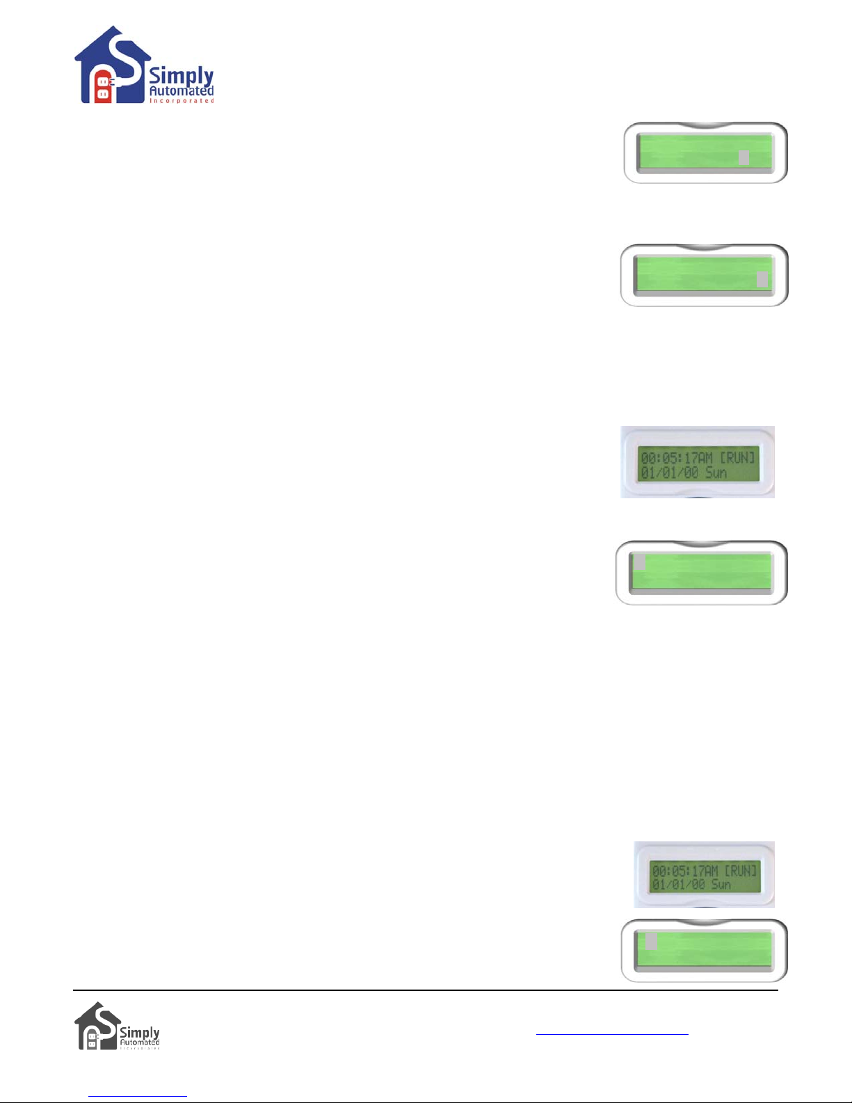
• Press the Right button to move the cursor to the hours segment (not the minutes)
of the ON time field. Press the Up button to scroll the ON time to dusk plus 00
minutes “DSK+00” (or your desired ON time).
• Press the Right button to move the cursor to the hours segment of the OFF time
field. Press the Down button to scroll the OFF time to 11:00 (or your desired OFF time). Press the Right
button two times to move the cursor to the AM/PM field, then press the Up (or Down) button to change the
field to “P” (for PM).
• Press the Right button to move the cursor to the Event Type field, then press the
Down button to set the Event type to “D0”, 100% ON. The Event Type can be a
dim level for dimmers (D1 = 10% dim… D5 = 50% dim… D9 = 90% dim, and D0 =
100% dim).
Press the Enter button to save the event. You’re done setting the first event. •
Section 4.b. Testing Event 01) for Relay Module #018
In the previous example the first relay module #018 (as labeled on the back of the unit) was set to turn ON at dusk
and OFF at 11PM, when the scheduler is in the normal runtime (RUN) schedule mode. To test this first event
“0
1)”:
Test Event 01). With the scheduler plugged into power, the Idle screen should be
displayed:
• From the Idle screen press the Down button. The first event will be displayed. Or,
press the Menu button to select “1) Set Event” and press Enter .
• With the first event displayed and the cursor on “01)” press the Enter button to
activate (turn on) the event. Press the Enter button again to deactivate (turn
off) the event. You should see the relay module #18 and the connected load
(transformer) turn ON and OFF as you press the Enter button.
Helpful Hint: If the connected load (transformer) does not turn ON/OFF, check that the relay module controlling
the load is labeled #18 (on the back of the unit) and make sure the event was saved correctly (e.g. matches
picture above with “DO” shown on the bottom right of the display). Check that the relay module is powered
(indicator lit) and the load is connected to the bottom receptacle of the relay module (not the front receptacle).
Also, check that the load’s (transformer’s) ON/OFF switch is in the ON position. Make sure the Network ID# is
250, per Section 3.c. If the transformer is still not turning ON/OFF, move the Scheduler-Timer to the transformer.
Plug the Scheduler-Timer into the front (always on) receptacle of the relay module and repea t test steps outlined
above. With the cursor on event number “01)” the relay module should turn ON/OFF wh en pressing the Enter
b
utton. You should be able to hear the relay module click ON and OFF. For further assistance see Section 6.
Section 4.c. Setting Event 02) for Relay Module #019
In this example the second relay module #019 (as labeled on the back of the unit) will be set to turn ON at dusk
(sunset) plus 15 minutes and OFF at dawn (sunrise), when the scheduler is in the regular runtime (RUN)
schedule mode. If you would like to set ON/OFF times other than Dusk+15/Dawn feel
free to do so.
Set Event 02). With the scheduler plugged into power, the Idle screen should be
displayed:
• From the Idle screen press the Down button. The first event will be displayed. Or,
press the Menu button to select “1) Set Event” and press Enter .
01)018 SMTWTFS R
DSK+00 11:00P LA
01)018 SMTWTFS R
DSK+00 11:00P D0
01)018 SMTWTFS R
DSK+00 11:00P D0
1)Set Events
2)Set Time
7
Simply Automated, Incorporated
6108 Avenida Encinas, Suite B,
Technical Support: www.simply
452-0001-0005WEB Rev. B Revised: September 22, 2011
Carlsbad, CA 92011 USA
-automated.com
or 800-630-9234
Page 8
Getting Started DKIT-05
Landscape-Outdoor Lighting Kit
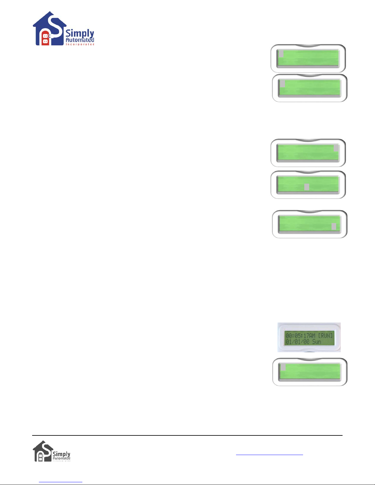
The scheduler will show the first event “01)”. With the cursor in the event •
um er field, press the Dow button ime to scroll to the next event “02)”.
n b n one t
With the cursor highlighting the event number “02)", press the Right button to
•
move the cursor over to the Device ID number field. Press the Up button to scroll
up to Device number 019. If yo
“019” is in the device ID field.
Press the Right button to move the cursor over to the days of the week field. Pressing the Up or Down button
•
u pass 019, press the Down button to go back, so
on any of the days of the week will change the capital letter to a lower case letter. Capital letter indicates an
ON day; lower case indicates an OFF day for this second “02)” event. Leave all the initials of the days of the
week (Sunday through Saturday) capitalized if you want the event to run every day; or change any day to a
lower case if you do not want this event to run on that day.
•
Press the Right button to move the cursor to the event mode field. Using the Up
or Down buttons set the event mo
de to “R” run, so the event will be active in the
normal runtime schedule mode.
•
Press the Right button to move the cursor to the hours segment (not the
minutes) of the ON time field. Press the Up button to scroll the ON time to dusk
plus 15 minutes “DSK+15” (or your desired ON time).
Press the Right button to move the cursor to the hours segment of the OFF time field. Press the Up button to
•
scroll the OFF time to dawn (sunrise) “DWN+00” (or your de sired OFF time).
Press the Right button to move the cursor to the Event Type field, then press the
•
Down button to set the Event type to “D0”, 100% ON.
Press the Enter button to save the event. You’re done setting the second event. •
Helpful Hint: Pressing the Enter
M
enu without saving changes.
button saves the changes made. Pressing Menu button will exit back to the
Helpful Hint: Pressing the Enter button when the cursor is on the Event number (e.g. “02”) will test the event
y toggling between ON and OFF each time Enter
b
is pressed.
Section 4.d. Testing Event 02) for Relay Module #019
The second relay module #019 (as labeled on the back of the unit) was set to turn ON at dusk plus 15 min utes
and OF
“0
Test Event 02)
d
• From the Idle screen press the Down button and the first event will be displayed,
F at dawn, when the scheduler is in the normal runtime (RUN) schedule
2)”:
. With the scheduler plugged into power, the Idle screen should be
isplayed:
mode. To test this second event
press the Down button a second time to view the second event “02)”.
• With the cursor on “02)” press the Enter button to activate (turn on) the event.
Press the Enter button again to deactivate (turn off) the event. You should see
the relay module #019 and the connected load (transformer) turn ON and OFF as you press the Enter
button.
Helpful Hint: If the connected load (transformer) does not turn ON/OFF, check that the relay module controlling
the load is labeled #19 (on the back of the unit) and make sure the event was saved correctly (e.g. matches
p
icture above with “DO” shown on the bottom right of the display). Check that the relay module is powered
01)018 SMTWTFS R
DSK+00 11:00P D0
02)---SMTWTFS R
12:00A 12:00A LA
02)019 SMTWTFS R
12:00A 12:00A LA
02)019 SMTWTFS R
DSK+15 DWN+00 LA
02)019 SMTWTFS R
DSK+15 DWN+00 DO
02)019 SMTWTFS R
DSK+15 DWN+00 DO
8
Simply Automated, Incorporated
6108 Avenida Encinas, Suite B, Carlsbad, CA 92011 USA
Technical Support: www.simply-automated.com
452-0001-0005WEB Rev. B Revised: September 22, 2011
or 800-630-9234
Page 9
Getting Started DKIT-05
Landscape-Outdoor Lighting Kit
(indicator lit) and the load is connected to the bottom receptacle of the relay module (not the front receptacle).
Also, check that the load’s (transformer’s) ON/OFF switch is in the ON position. Make sure the Network ID
# is
250, per Section 3.c. If the transformer load is still not turning ON/OFF, move the Scheduler-Timer to the
transformer. Plug the Scheduler-Timer into the front receptacle of the relay module and repeat test steps outlined
above. With the cursor on event number “02)” the relay module should turn ON/OFF wh en pressing the Enter
b
utton. You should be able to hear the relay module click ON and OFF. For further assistance see Section 6.
Section 4.e. Setting Event 03) for a Group (SCENE) of Modules
The relay modules #018 and #019 (as labeled on the back of the units) are pre-configured to operate with the
optional 4 and 8 button scene controller accessories (see Section 5 for more details). In this example the “All O
N”
lighting scene link ID #019 (associate with button 3 of the scene controllers) will be used to by the scheduler to
turn ON both modules at dusk (sunset) minus
15 minutes and OFF at midnight (12:00AM); when the sch
eduler is
in the regular runtime (RUN) schedule mode.
Set Event 0
isplayed:
d
•
d played.
From the Idle screen press the Down button. The first event will be is
select “1) t Eve ” and press Enter
The scheduler will show the first event “01)”. With the cursor in the event
•
um er field, press the Dow button
n b n two times to scroll to the third event “03)”.
3). With the scheduler plugged into power, the Idle screen should be
Or, press the Menu button to
Se nt .
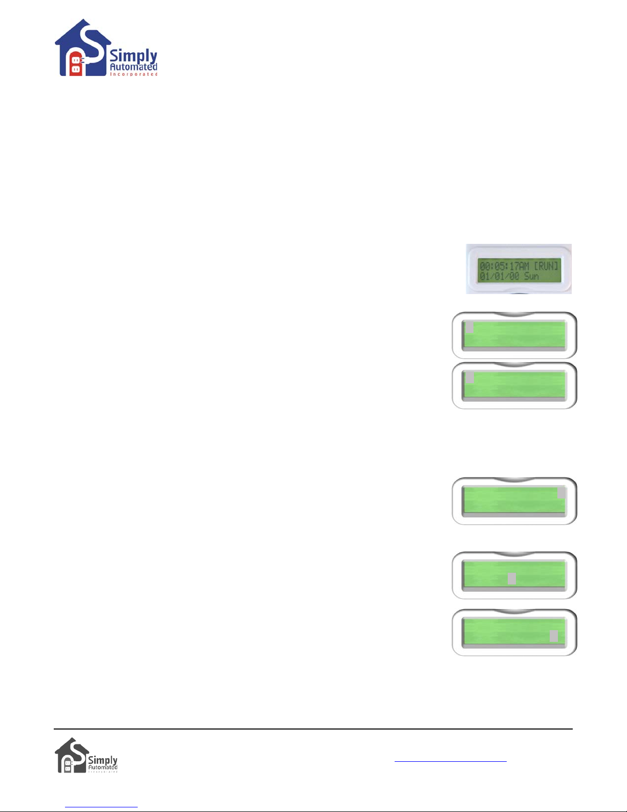
01)018 SMTWTFS R
DSK+00 11:00P D0
•
With the cursor highlighting the event number “03)", press the Right button to
move the cursor over to the Scene Link
ID number field. Press the Up button to
scroll up to Scene Link number 019.
Press the Right button to move the cursor over to the days of the week field.
•
03)--- SMTWTFS R
12:00A 12:00A LA
Pressing the Up or Down button on any of the days of the week will change the capital letter to a lower case
letter. Capital letter indicates an ON day; lower case indicates an OFF day for this third “03)” event. Leave a
the initials of the days of the week (Sunday through Saturday) capitalized if you want the
event to run every
day, or change any day to a lower case if you do not want this event to run on that day.
Up
Press the Right button to move the cursor to the event mode field. Using the
•
or Down buttons set event mode
to “R” run, so the event will be active in the
normal runtime schedule mode.
Press the Right button to move the cursor to the hours segment (not the
•
minutes) of the ON time field. Press the Up button to scroll the ON time to dusk mi
time
Press the Right button to move the cursor to the hours segment of the OFF
•
field. If necessary,
press the Up (or Down) button to scroll the OFF time to
03)019 SMTWTFS R
12:00A 12:00A LA
nus 15 minutes “DSK-15”.
03)019 SMTWTFS R
DSK-15 12:00A LA
midnight “12:00A”.
Press the Right button to move the cursor to the Event Type field. If necessary,
•
press the Up (or Down) button to set the Event type to scene link activator “LA”.
• Press the Enter button to save the event. You’re done setting the third event.
Helpful Hint: Pressing the Enter
M
enu without saving changes.
Helpful Hint: Pressing the Enter button when the cursor is on th
b
y toggling between ON and OFF each time Enter
button saves the changes made. Pressing Menu button will exit back to the
e Event number (e.g. “03”) will test the event
is pressed.
03)019 SMTWTFS R
DSK-15 12:00A LA
Simply Automated, Incorporated
6108 Avenida Encinas, Suite B, Carlsbad, CA 92011 USA
Technical Support: www.simply-automated.com
452-0001-0005WEB Rev. B Revised: September 22, 2011
or 800-630-9234
9
ll
Page 10
Getting Started DKIT-05
Landscape-Outdoor Lighting Kit
Section 4.f. Testing Event for a Group (SCENE) of Modules
You can repeat the process for testing an event (e.g. event “03”) outlined in Section 4.d. Sim
b
utton when the cursor is on the Event number (e.g. “03”) to toggle the scene ON and OFF.
ply press the Enter
Helpful Hint: If the connected loads (transformers) do not turn ON/OFF, check to make sure the event was saved
correctly (e.g. matches picture above with “LA” shown on the bottom right of the display). Check that the loads
are connected to the bottom receptacle of relay modules (not front receptacle). Also, check that the relay module
is powered (indicator lit) and the load’s (transformer’s) ON/OFF switches are in the ON po sition. Make sure the
Network ID# is 250, per Section 3.c. If the transformer loads are still not turning ON/OFF, move Scheduler-Timer
to the transformer. Plug the Scheduler-Timer into the front receptacle of the relay module and repeat test steps
outlined above. With the cursor on event number “03)” the relay module should turn ON/OFF when pres sing the
bu
Enter
S
ection 6.
tton. You should be able to hear the relay module click ON and OFF. For further assistance see
Section 4.g. Other Functions of the Scheduler-Timer
To learn more about the Scheduler-Timer and functions such as deleting an event or setting randomness plea se
http:
refer to the User Guide enclosed in the Scheduler-Timer product box or find it on line at:
//www.simply-
automated.com/documents/452-0031-0101_RevB-WEB_UCS-01_User_Guide_090824.pdf.
Section 5: Simple-n-Easy Expansion for SimplySmartTM Series. Fully Compatible. All
Starter Kits & Accessories -- Dimmers, Tabletop Controllers, Receptacles, Lamp,
ppliance and Fixture Modules, plus Scheduler-Timer. A
Simply Automated Pre-Configured SimplySmart
the Dimmer or Lamp Starter Kit, add other starter kits, additional standard dimmers, additional Deluxe Dimmers
with 4-buttons, additional modules, Tabletop Controllers with 4 or 8-buttons or any of the other pre-configured
or accessories. All the pre-configured kits and accessories can be edited and added to scenes as previously
described – only limitation being not more than one of each model number or kit number per installation. One
touch button convenience to turn ON/OFF up to ten or more Simply Automated devices – custom scenes you
c
reate!
TM
Series offers simple-n-easy expansion capability. Begin with
kits
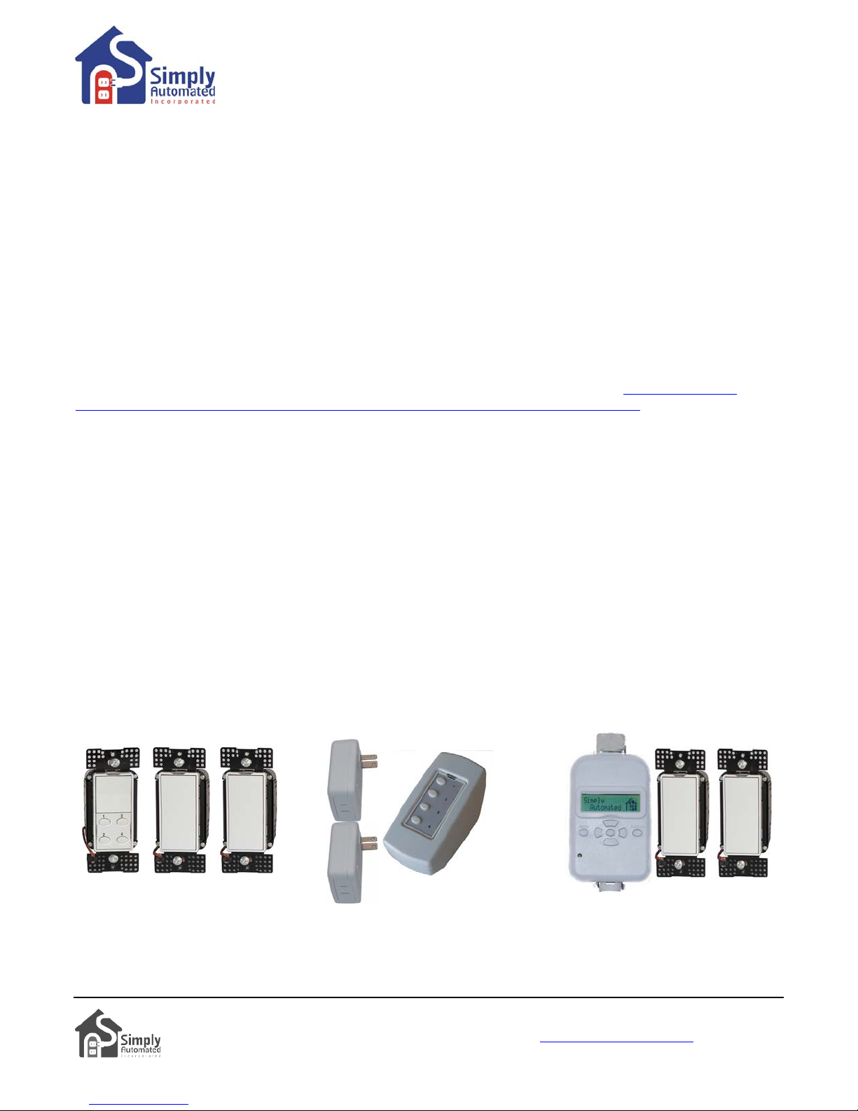
Dimmer Starter Kit Lamp Starter Kit Landscape Dimmer
Includes 2 dimmers and deluxe Includes 2 lamp modules and Starter Kit Includes 2 standard
dimmer with 4-button scene tabletop controller with 4-button standard dimmers and s
c
ontroller (model: DKIT-01). scene controller (model: DKIT-02) timer (model: DKIT-06)
cheduler-
Simply Automated, Incorporated
6108 Avenida Encinas, Suite B, Carlsbad, CA 92011 USA
Technical Support: www.simply-automated.com
452-0001-0005WEB Rev. B Revised: September 22, 2011
or 800-630-9234
10
Page 11
Getting Started DKIT-05
Landscape-Outdoor Lighting Kit
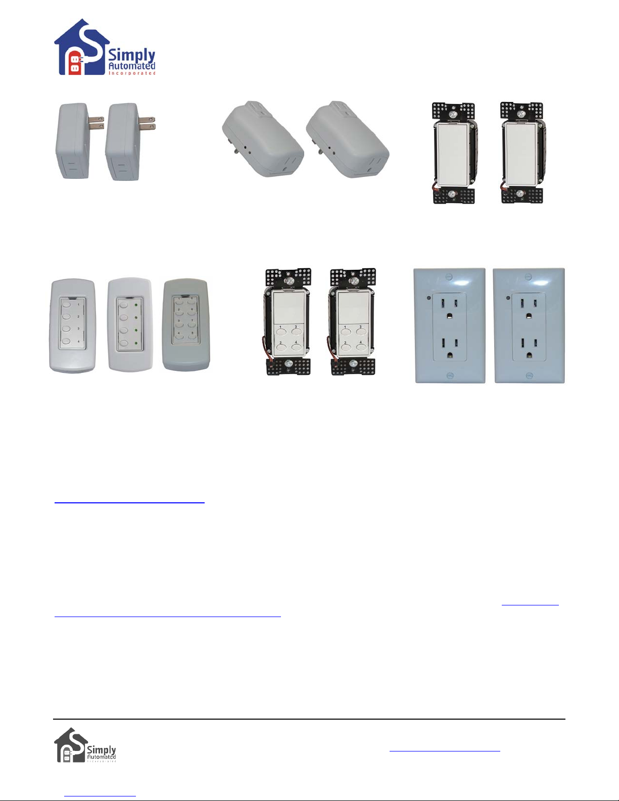
Lamp Modules Relay Modules Dimmers
UML7 UML8 UMA25 UMA26
US1W9 US1W10
Tabletop Controllers Deluxe Dimmers Controlled Receptacles
(with 4 or 8-button scene control) (with 4-button scene control) (top receptacle controlled
bottom receptacle always on)
US2TP11 USQT22 US28OTP23 US2W12 US2W24 URD27 URD28
Important Note: only one of each pre-configured accessory model number can be ordered per home
installation.
Section 6: In Case of a Problem
Phone: 760-431-2100 Ext. 138 Monday-Friday 8AM-5PM (Pacific Time) for assistance, or write to
Phase Coupler: Your home should be no more than 2500 square feet and have only one breaker panel. A pha se
coupler is required in some home installations; especially homes > 2500 square feet or homes with more than 1
breaker panel. If you have tested the scheduler for each relay module, but one or more of the relay modules do
not turn on, the circuits in your home may need phase coupling or phase alignment.
All homes have a 240V feed to the main breaker panel box, where the 240V is separated into 120V in two
phases, an A and B. You will need to install a phase coupler, or use devices on one phase (align or move lighting
circuits, at the breaker, that have these dimmers and modules to either phase A or B, not both), see
automated.com/products/cats/phase_couplers.php for options.
Model # Description
ZPCI-P30A Plug-In Inverting Phase Coupler, fits a standard (NEMA 10-30) 240VAC / 30 Amp clothes
dryer type outlet
ZPCI-P50A Plug-In Inverting Phase Coupler, fits a standard (NEMA 10-50) 240VAC / 50Amp clothes
dryer type outlet
ZPCI-W Wire-in Inverting Phase Coupler
ZPCI-B Breaker Panel Inverting Phase Coupler
http://simply-
11
Simply Automated, Incorporated
6108 Avenida Encinas, Suite B, Carlsbad, CA 92011 USA
Technical Support: www.simply-automated.com
452-0001-0005WEB Rev. B Revised: September 22, 2011
or 800-630-9234
Page 12
Getting Started DKIT-05
Landscape-Outdoor Lighting Kit
Section 7: Simply Automated Custom Expansion Series
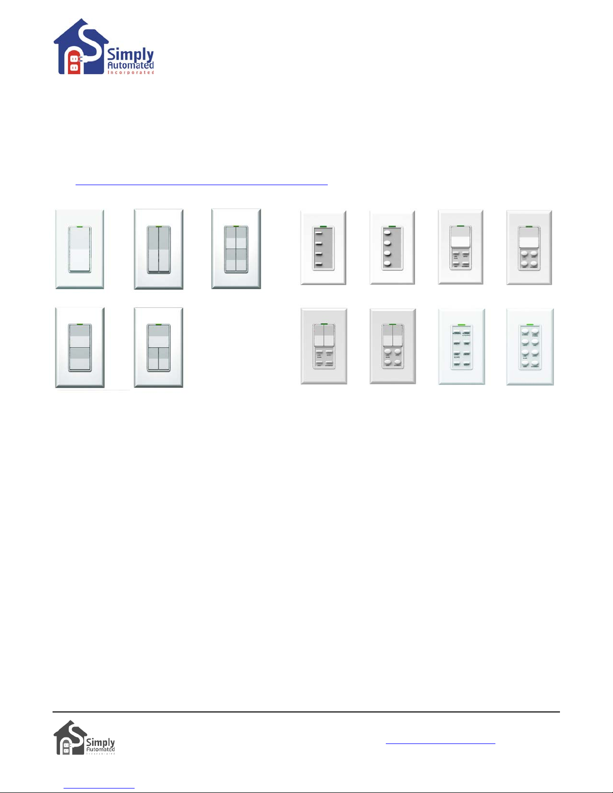
Powerful Custom Expansion Capability – up to 250 devices – using your PC and UPStart software! Devices
include single rocker dimmers, deluxe dimmers with different faceplates (up to 8 buttons), lamp or appliance
modules, tabletop pedestal with 4 or 8 buttons, wall receptacle, fixture relay, fixture dimmer or Scheduler-Timer.
Control lighting and 120VAC appliances, heaters, fans, motors or pumps. Programmable dimming rates (1
second, 5 second, up to 4 hours). Energy saving countdown timer function. Lighting control for your entire home!
http://www.simply-automated.com/products/products.php
Visit
12
Simply Automated, Incorporated
6108 Avenida Encinas, Suite B, Carlsbad, CA 92011 USA
Technical Support: www.simply-automated.com
452-0001-0005WEB Rev. B Revised: September 22, 2011
or 800-630-9234
 Loading...