

Page 1
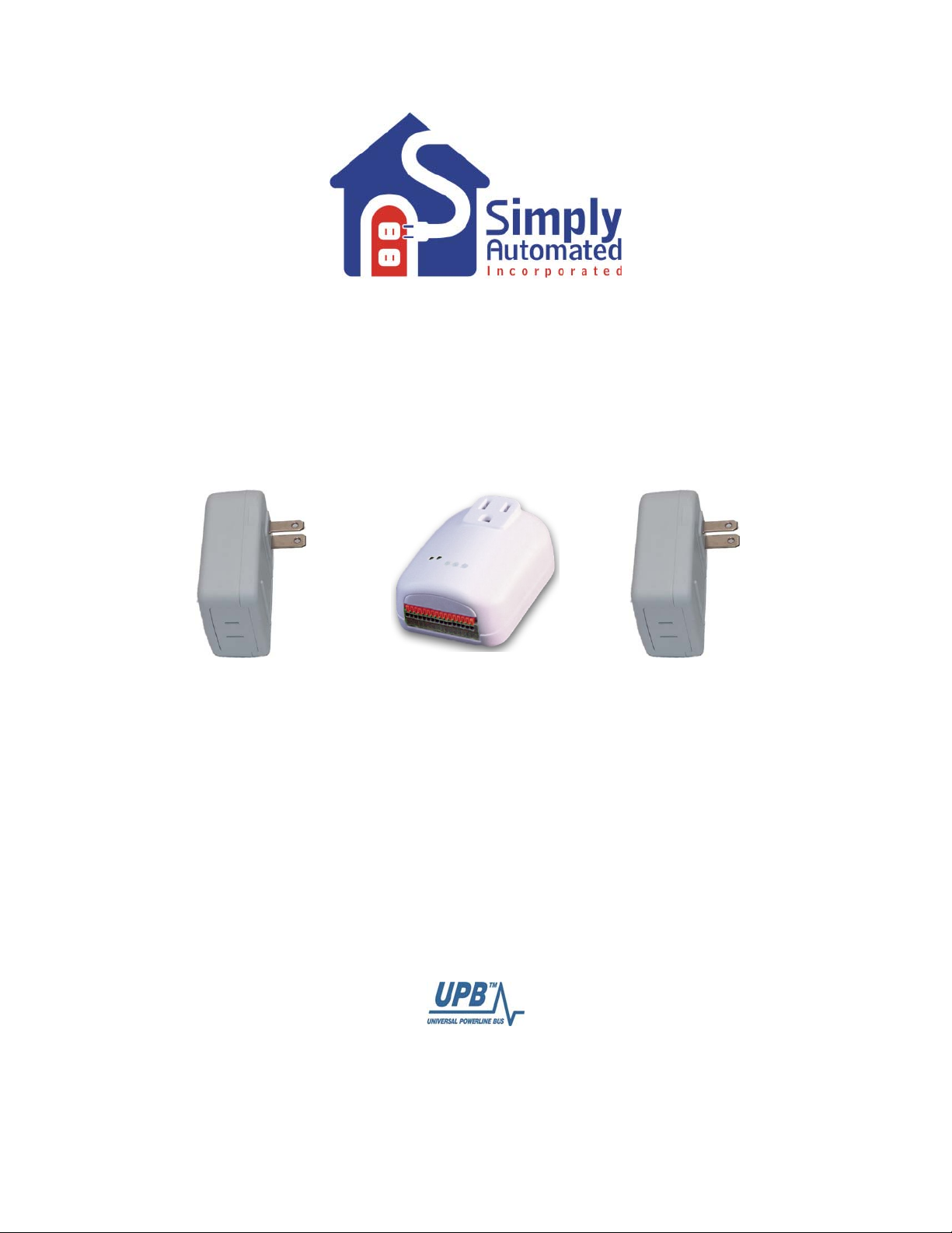
Lamp Module Starter Kit
Model DKIT-03SP
Getting Started
Simply Automated Pre-Configured SimplySmartTM Series
Utilizes SimplySmart
programming required! Simple-n-easy, ready to use lighting control.
TM
technology to make installation a breeze. No computer
Page 2

Getting Started
DKIT-03 Lamp Module Starter Kit
Simply Automated Pre-Configured SimplySmartTM Series
Simple-n-easy, ready to use lighting control. No computer programming required!
Utilizes SimplySmart
IMPORTANT SAFETY INSTRUCTIONS
When using electrical products, basic safety precautions should always be followed, including the following:
1. READ AND FOLLOW ALL SAFETY INSTRUCTIONS.
2. Installation should be performed by a qualified electrician.
3. Keep away from water. If product comes into contact with water or other liquid, disconnect immediately.
4. Never use products that have been dropped or damaged.
5. Do not use this product outdoors.
6. Do not use this product for other than its intended use.
7. Do not connect multiple lamps that, when combined, exceed the maximum load rating of the product, de-rated for
multi-gang boxes.
8. Do not install in areas that can exceed 120°F (e.g., in an attic).
9. To avoid the risk of overheating and possible damage to other equipment, do not use this product to control a
receptacle.
10. Do not cover the product with any material when in use.
11. SAVE THESE INSTRUCTIONS.
TM
technology to make installation a breeze.
Security Panel Lamp Starter Kit
Easily Connect Simply Automated Lighting to Any Alarm Panel with Low Voltage or Contact
Output Capability. (PN: DKIT-03SP) includes 2 Lamp Modules and 1 I/O Module with 3 inputs/2
outputs.
Getting Started
Section 1: Very Important Pre-Installation Notes
• The security panel will need one or more low voltage or contact closure outputs to
interface with the I/O Module.
• Your home should be no more than 2500 square feet and have only one breaker panel.
A phase coupler is required in some home installations. See Section 5 for more
information.
• Not intended for use in multi-dwelling (condo, apartment, duplex) units.
Section 2: Installation of the Lamp Modules and I/O Module
Section 2.a. Installation of the Lamp Modules
Locate 2 lamps you would like to turn ON/OFF. Plug a lamp module into a wall outlet, then plugin a lamp into the socket on the bottom of the lamp module. Turn the lamp ON using the lamp’s
ON/OFF switch. Repeat this process for second lamp module. You're done with the installation
process! Please refer to the User Guide or see
0112-0201_RevC_UML-E-W_UserGuide_090512.pdf.
http://simply-automated.com/documents/452-
Simply Automated, Incorporated
6108 Avenida Encinas, Suite B, Carlsbad, CA 92011 USA
Technical Support: www.simply-automated.com
452-0003-1001 Rev. B Revised: July 7, 2009
or 800-630-9234
Page 3
Getting Started
DKIT-03 Lamp Module Starter Kit
Important note: each lamp module has a specific device ID #. You can find the device ID # on
the box the lamp module came packaged in and also on the back of each lamp module. One
lamp module has device ID #14 and the other has device ID #15. This is important information, it
relates to operation with the Input/Output Module and Pocket Programmer (sold separately).
Section 2.b. Installation of the I/O Module
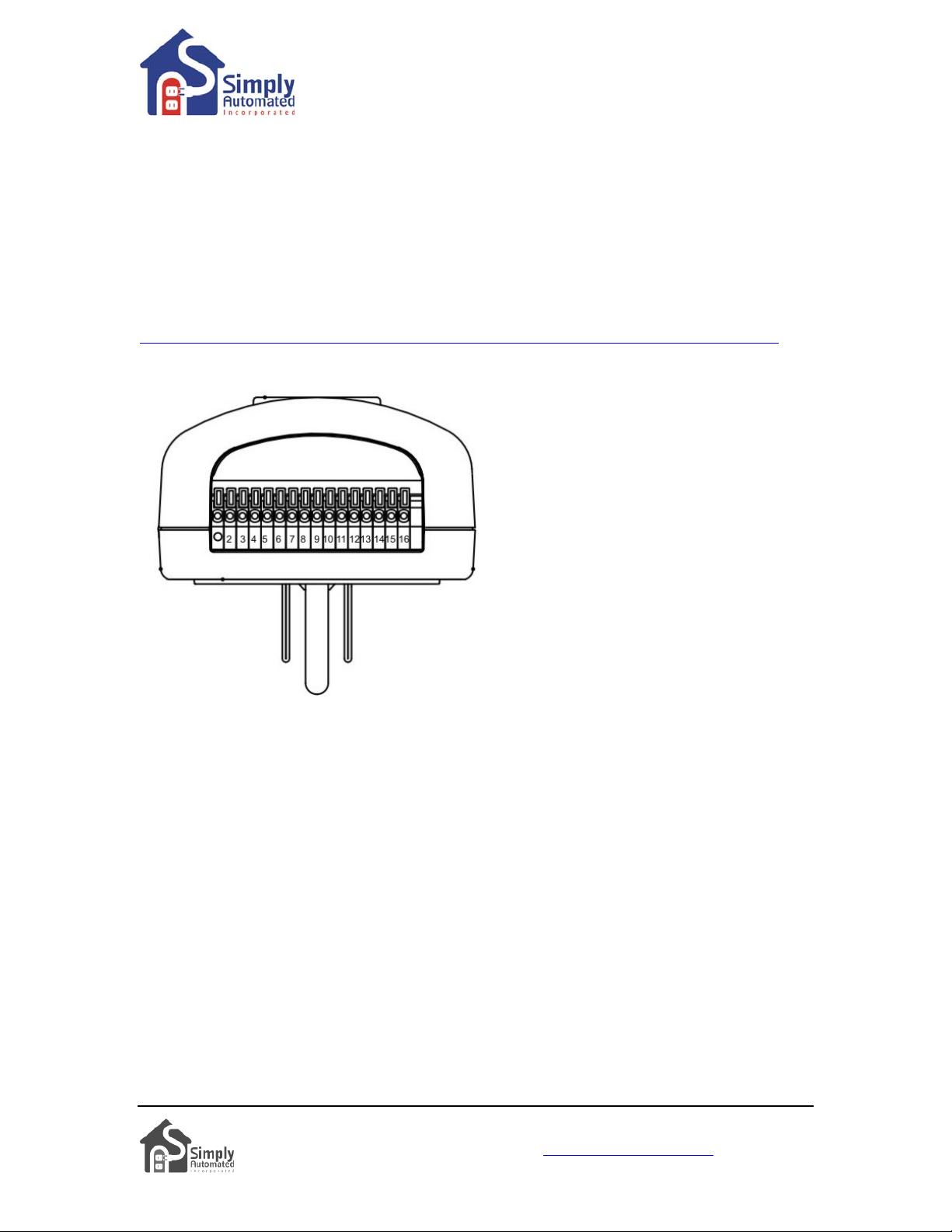
Locate a 110 VAC power receptacle in (or near) the alarm panel and plug-in the I/O Module. The
I/O Module has 3 pre-configured inputs (3 low voltage 4-5VAC/DC or 2 contact closure) to turn
on/off the 2 lamp modules. Refer to User Guide in box the I/O Module came packaged in or see
http://simply-automated.com/documents/452-0003-0001_RevE_UMI_UserGuide_090512.pdf.
The discrete low voltage or contact closure trigger outputs of the security panel need to be
connected to the proper terminals of the I/O Module.
Input 1: Low Voltage (only), terminals 6 and 7
Turns on/off first lamp module (#14)
Input 2: Contact, terminals 9 and 10
OR
Input 2: Low Voltage, terminals 8 and 9
Turns blinking on/off for all lamp modules
Input 3: Contact, terminals 15 and 16
OR
Input 3: Low Voltage, terminals 14 and 15
Turns on/off all lamp modules
Note: Low voltage inputs are differential (i.e.
positive or negative polarity does not matter).
Pre-Configured Input 1: Low voltage input. Turns on first lamp module (#14) when trigger is
enabled. Turns off first lamp module when trigger is disabled. Used for delay entry/exit (lights on
for entry, off for exit), arm/disarm acknowledgement, door strike or motion sensor interface.
Installer needs to program security panel for each trigger interface. Low voltage wires (provide 0
Volt ‘off‘ or 4-5 Volt ‘on’ trigger) from security panel connect to input terminals 6/7 of the I/O
Module.
Pre-Configured Input 2: Low voltage or contact closure input. Turns on both lights and flashes
when triggered is enabled. Turns off lights and stops flashing lamp module s when trigger is
disabled. Used for fire, intrusion or panic alarms. Installer needs to program security panel for
alarm type and trigger. Low voltage wires (provide 0 Volt ‘off’ or 4-5 Volt ‘on’ trigger) from
security panel connect to input terminals 8/9, or contact closure wires (provide open – ‘off’ or
closed – ‘on’ trigger) connect to input terminals 9/10 of the I/O module.
Pre-Configured Input 3: Low voltage or contact closure input. Turns on both lights when trigger is
enabled. Turns off both lights when trigger is disabled. Used for fire, intrusion or panic alarms.
Installer needs to program security panel for alarm type and trigger. Low voltage wire s (provide 0
Volt ‘off’ or 4-5 Volt ‘on’ trigger) from security panel connect to input terminals 14/15, or contact
closure wires (provide open – ‘off’ or closed – ‘on’ trigger) connect to input terminals 15/16 of the
I/O Module.
Simply Automated, Incorporated
6108 Avenida Encinas, Suite B, Carlsbad, CA 92011 USA
Technical Support: www.simply-automated.com
452-0003-1001 Rev. B Revised: July 7, 2009
or 800-630-9234
Page 4
Getting Started
DKIT-03 Lamp Module Starter Kit
Testing the I/O Module and 2 lamp modules:
• Input 1: Apply a low voltage source (i.e., 9V DC battery) to input terminals 6/7 of the I/O
Module to turn on first lamp module (#14). Disconnect battery to turn off lamp module.
• Input 2: Apply a low voltage source (i.e., 9V DC battery) to input terminals 8/9 of the I/O
Module to flash both lamp modules. For contact closure, apply input (i.e., short circuit with
#18 wire) to input terminals 9/10 of the I/O Module. Remove low voltage source, or contact
closure source to turn off both lamp modules.
• Input 3: Apply a low voltage source (i.e., 9V DC battery) to input terminals 14/15 of the I/O
Module to turn on both lamp modules. For contact closure, apply input (e.g. short circuit with
#18 wire) to input terminals 15/16 of the I/O Module. Remove the low-voltage or contact
closure source to turn off both lamp modules.
Important Note: You will hear a soft buzz when the I/O Module is transmitting a signal to the
lamp modules. If you hear a buzz, but one or both of the lamp modules do not turn on/off,
lamp's switch may be in the off position. Go to the lamp and turn on using the lamp's on/off
switch. If the lamp module still does not turn on/off,
see Section 5, Phase Coupler.
the
Section 3: Adding Additional Dimmers and Lamp Modules
Simply Automated Pre-Configured SimplySmart
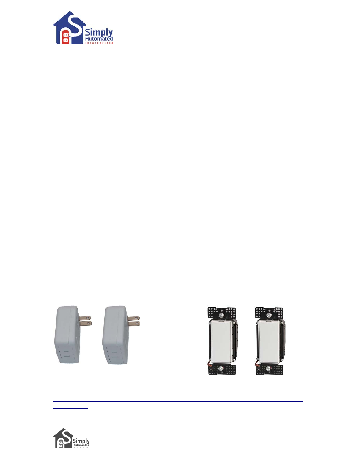
capability. Add up to two additional dimmers or lamp modules to the Security Panel Lamp
Module Starter Kit. Fully compatible accessories will interface with the I/O Module and your
security panel out of the box! Each accessory dimmer or lamp module added will automatically
blink on/off when input 2 of the I/O Module is triggered by the security panel, will go on/off when
input 3 is triggered.
TM
Series offers simple-n-easy expansion
Lamp Modules Dimmers
PN: UML7 PN: UML8
PN: US1W9 PN: US1W10
Important Note: only one of each pre-configured accessory PN can be ordered per home
installation.
Simply Automated, Incorporated
6108 Avenida Encinas, Suite B, Carlsbad, CA 92011 USA
Technical Support: www.simply-automated.com
452-0003-1001 Rev. B Revised: July 7, 2009
or 800-630-9234
Page 5
Getting Started
DKIT-03 Lamp Module Starter Kit
Section 4: Adding Lighting Control and Automation
You can have even more lighting power with Simply Automated’s pre-configured lighting control
kits and accessories. Fully compatible with the I/O Module and your security panel out of the box!
Each accessory dimmer or lamp module added will automatically blink on/off when input 2 of the
I/O Module is triggered by the security panel, will go on/off when input 3 is triggered.
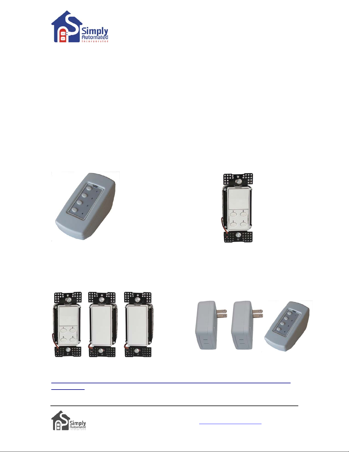
Create your own special lighting scenes (i.e., reading, dining, entertaining) with our 4-button
scene controllers. Push a button to turn on one light or a group of lights. Push a button to turn on
all lights on. Push a button to turn all lights off. Manually edit (add or delete) a dimmer or lamp
module from any button. Simple-n-easy one touch button control.
Tabletop Controller Deluxe Dimmer
With 4-button scene control With 4-button scene control
PN: US2TP11
PN: US2W12
Dimmer Starter Kit
Includes 2 dimmers and deluxe dimmer Includes 2 lamp modules and tabletop
With 4-button scene control controller with 4-button scene controller.
(PN: DKIT-01)
: Lamp Starter Kit
(PN: DKIT-02)
:
Important Note: only one of each pre-configured accessory PN can be ordered per home
installation.
Simply Automated, Incorporated
6108 Avenida Encinas, Suite B, Carlsbad, CA 92011 USA
Technical Support: www.simply-automated.com
452-0003-1001 Rev. B Revised: July 7, 2009
or 800-630-9234
Page 6
Getting Started
DKIT-03 Lamp Module Starter Kit
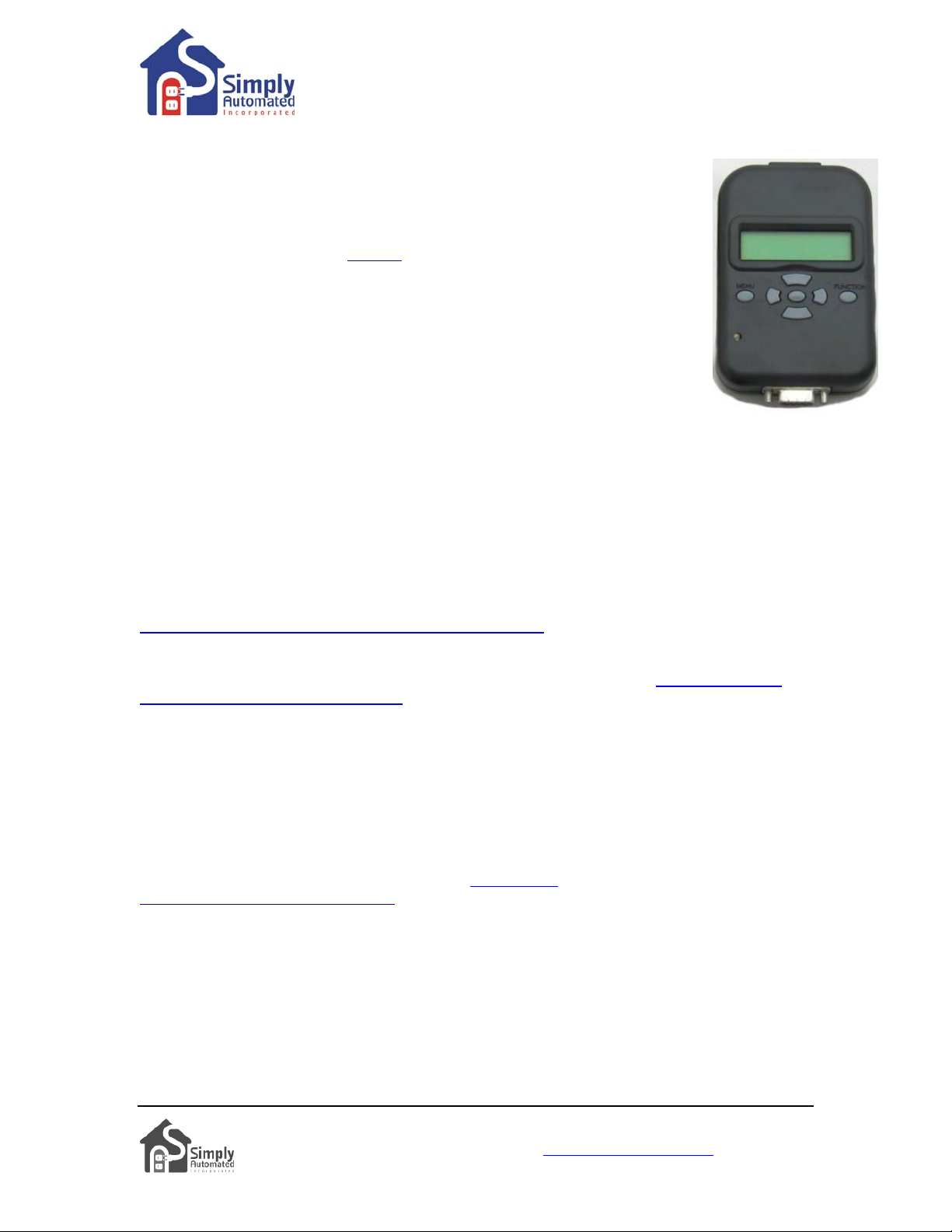
Section 5: Using the Pocket Programmer (sold separately)
If you plan to do multiple installations, we highly recommend you purchase a
Pocket Programmer (Model #
powerful and simple tool for the dealer or installer.
UPP-20). The Pocket Programmer is a very
1. Network ID. Each device in the pre-configured series has the same network
ID (250). The Pocket Programmer can be used to change the network ID in the
pre-configured series to provide a unique ID for each installation, an important
security feature. This will also prevent potential 'cross-chatter' with a neighbor’s
lighting system.
2. Links. Each input has a defined link. Input 1 has been assigned link 66
(on/off for one device), Input 2 has been assigned link 65 (blinking on/off for all devices), Input 3
has been assigned link 64 (on/off for all devices). All pre-configured accessory dimmers and
lamp modules will automatically work with Inputs 2 and 3.
3. Testing Signal Strength and Noise. In some cases, there may be noise (interference) issues
on the powerline from other electrical devices in the home that might interfere with the operation
of the lighting system. You can quickly test for any noise on your system by doing a noise check.
4. Computer Interface Module. The Pocket Programmer can be used as a computer interface
module with your PC using a serial connection. With UPStart software (available at
http://www.simply-automated.com/products/sa_upstart.htm), you have a powerful tool for custom
installations.
To learn more about the Pocket Programmer and how it can be used go to
automated.com/products/sa_UPP.htm
http://www.simply-
Section 6: In Case of a Problem
Phone: 760-431-2100 Ext..138 Monday-Friday 8AM-5PM (Pacific Time) for assistance.
Phase Coupler: If you have tested the lamp modules, they work, but the I/O Module does not
turn on all the lamp modules, the circuits in your home may be out of phase. All homes have a
220V feed to the main panel box, where the 220V is separated into 110V in two phases, an A and
B. You will need to install a phase coupler, see
automated.com/products/sa_zpc.htm for more details.
Model # Description
ZPCI-P30A Plug-In Inverting Phase Coupler, fits a standard (NEMA 10-30) 220VAC clothes
dryer outlet
ZPCI-W Wire-in Inverting Phase Coupler
ZPCI-B Breaker Panel Inverting Phase Coupler
http://simply-
Simply Automated, Incorporated
6108 Avenida Encinas, Suite B, Carlsbad, CA 92011 USA
Technical Support: www.simply-automated.com
452-0003-1001 Rev. B Revised: July 7, 2009
or 800-630-9234
Page 7
Getting Started
DKIT-03 Lamp Module Starter Kit
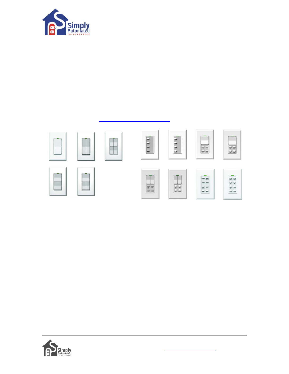
Section 7: Simply Automated Custom Expansion Series
Powerful Custom Expansion Capability using your PC, Computer Interface Module (PN: UMCUSB) and UPStart software – up to 250 devices! Devices include single ro cker dimmers, deluxe
dimmers with different faceplates (up to 8 buttons), lamp or appliance modules, tabletop pedestal
with 8 buttons, wall receptacle, fixture relay, fixture dimmer or scheduler-timer. Control lighting
and 120VAC appliances, heaters, fans, motors or pumps. Programmable dimming rates (1
second, 5 second, up to 4 hours). Energy saving countdown timer function. Lighting control
for your entire home! Visit
http://www.simply-automated.com.
Simply Automated, Incorporated
6108 Avenida Encinas, Suite B, Carlsbad, CA 92011 USA
Technical Support: www.simply-automated.com
452-0003-1001 Rev. B Revised: July 7, 2009
or 800-630-9234
 Loading...