

Page 1
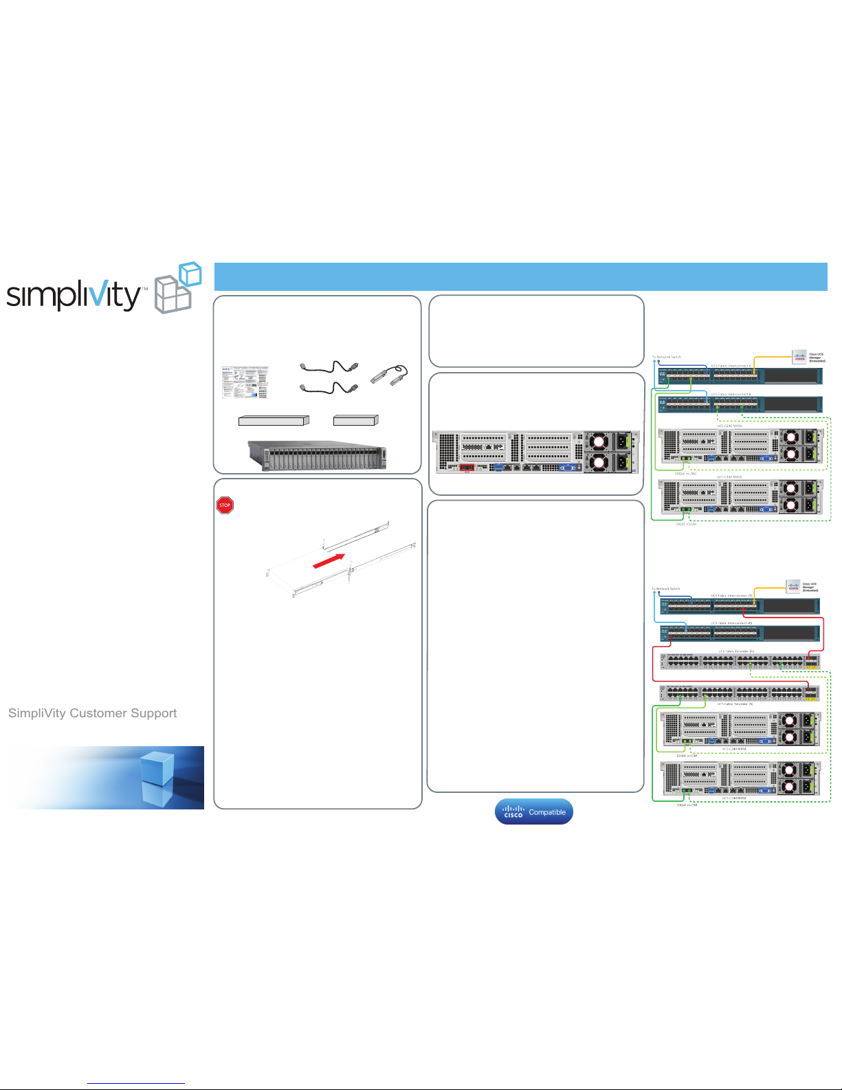
Federation Networks
Federations require three networks, separated
physically and, optionally, by VLANs:
● Use redundant connections and switches.
● Provide multiple network paths between components.
Required Hardware (Not Provided)
● Standard 19” four-post rack. Each system needs 2U
of rack space.
● Cisco UCS Series Fabric Interconnects (FI) if using
UCS Manager (UCSM).
● 10GbE or 1GbE Management network
● 10GbE Storage network
● 10GbE Federation network
Direct Connect Mode Cluster
Use redundant direct connections between two systems
and FIs in different fabrics for the Management, Storage,
and Federation networks. No 1GbE interfaces for the
Management network.
760-000127 Rev B
Network Cabling Examples
For high availability, use different circuits for each power supply, with
an uninterruptible power supply (UPS) backup. Insert a power cord to
each power supply and then insert the power cord into a grounded AC
power outlet or a rack PDU.
Wait two minutes until the front panel Power Status LED glows amber,
indicating standby power mode.
Network Recommendations for High Availability
6. UCS C240 M4SX Enclosure
Task 1: Unpack the Shipping Carton
Warning: The systems are heavy and require two people
to lift and install them in a rack.
Task 2: Install the Enclosure in a Rack
Caution: Read the installation instructions included in the rail
kit for important procedural and safety information. Failure to
follow the rail kit instructions might result in personal injury or
property damage.
Task 5: Configure UCSM
OmniStack Quick Start–UCS C240 M4SX Hardware Installation
Task
3: Connect the Power Cables
SimpliVity Customer Support
SimpliVity Customer Support
To contact SimpliVity Customer Support, visit
http://www.simplivity.com/support
Continue to the Conguration and Deployment Quick Start.
Copyright 2015 SimpliVity Corporation
You deploy two UCS C240 M4SX systems to create a
SimpliVity Global Federation.
This Quick Start explains how to install a UCS C240 M4SX
system into a rack and integrate it into your environment.
Refer to these documents, available from the Online
Support Center (login required):
Read This First
● OmniCube™ Release Notes
● OmniStack™ Integrated Solution with Cisco UCS C240
M4SX Hardware Installation and Maintenance Guide
You use UCSM to integrate the system into your environment. The
integration tasks are listed below.
SingleConnect Cluster
If using FEX devices, optionally use redundant connections
between two systems for the Management, Storage, and
Federation networks, through FEX devices, and then FIs.
No 1GbE interfaces for the Management network.
Optional Hardware (Not Provided)
● Cat-5E or Cat-6 Ethernet cables (RJ45) for all 1GbE
links.
● Cisco KVM Cable Adapter.
● Cisco Fabric Extenders (FEX) if using FIs.
● Reset the CIMC factory default from Standalone Mode to UCSM
Integrated Mode.
● Ensure Firmware Auto Sync Server Policy is set to No Actions.
● Power-on the system and wait for UCSM to discover it.
● Create these policies in UCSM:
- BIOS Policy: Specifies the SimpliVity BIOS settings.
- Host Firmware Package Policy: Specifies the system firmware.
- Local Disk Config Policy: Specifies RAID for the front disk drives.
- Boot Policy: Specifies booting from the internal SD card.
- QoS Policy: Specifies an MTU of 9000 for the Storage and
Federation networks.
● (Optional) Create uplink ports for each FI to control traffic between
the FIs and the next layer of your network.
● (Optional) Create a LAN Pin Group to control traffic between the
system and the uplink ports (targets).
● Create MAC address pools for assigning MAC addresses to the
network interfaces.
● Configure 4 vNIC Templates (2 Management and 2 Storage) for the
10GbE mLOM interfaces.
● (Optional) Create a vNIC Placement Policy.
● Create a LAN Connectivity Policy.
● Create a Service Profile Template using the policies and settings
above.
● Set UUID assignment on the Service Profile Template to use the
hardware default.
● Create a Service Profile using the Service Profile Template above.
● Associate the Service Profile to the system.
● Configure an IPv4 address for accessing the KVM Virtual Console.
UCSM Integration Tasks
Do not press the front panel power button yet.
1. Quick Starts and
Product Guide
4. Rail Kit and Instructions
Shipping Carton Contents
5. Cable Management Arm (Optional)
2 x Power
2 x Rack PDU
2. Power Cables (Locale-specific)
1. Align the rear system rails with the front of the rack slide rails.
2. Slide the system into the rails until it stops at the rail stops.
3. Slide the release clip on each inner rail toward the rear.
4. Push the system into the rack until the front latches engage
with the rack posts.
5. Optionally, use the two screws in the rail kit to secure the system
to the rack. Open each front latch and insert the screw through
the hole under the lever.
Install the Rail Kit
1. Align the three slots on each rail with the pegs on the system.
2. Slide the rails forward to lock them in place.
3. Push the green arrow button toward the rear to open the front
securing plate on each slide rail assembly.
4. Align the slide assembly with the rack front post hole.
5. Insert the mounting pegs on the slide assembly into the rack post
holes from the outside front.
6. Push the securing plate release button (marked PUSH) to lock
the pegs in place.
7. Adjust the slide rail length and then push the rear pegs into the
rear post holes.
Note: Ensure the slide rail assemblies are at the same height
and level front-to-rear.
8. Pull the inner slide rails out to the front until they lock in place.
Mount the Enclosure
If using Cisco Integrated Management Controller (CIMC) to manage a
system in Standalone Mode, continue to Task 4 on the back.
If using UCSM to manage a system in Integrated Mode, use the two
10GbE mLOM network interfaces (in red) to connect the system to
each FI. See Network Cabling Examples to the right.
Note: For switched networks, connect both 10GbE network interfaces
to redundant switches. Use VLANs to separate the networks.
Task
4: Connect the Network Cables
The contents vary depending on the requested components.
Important: See the
Hardware Installation and Maintenance Guide
for detailed information about each task.
Required Hardware (Provided)
● 2 SFP+ Direct Attach 10GbE passive cables.
3. 2 x SFP+ Direct Attach
10GbE Passive Cables
● Switched links provide adequate bandwidth.
● Jumbo Frames (MTU 9000) value is consistent across
all 10GbE devices and endpoints in each network.
● MTU 1500 value is consistent across all 1GbE devices
and endpoints in each network.
Network Requirements
Page 2
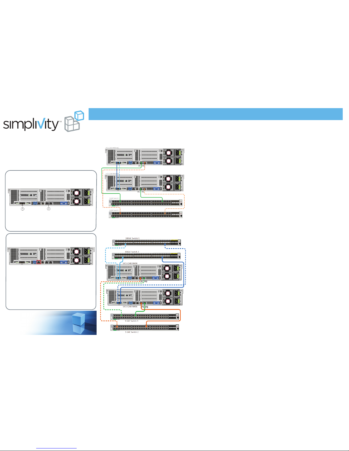
Switch-Connected Configuration
Direct-Connected Configuration
Use redundant, 10GbE direct connections between two
systems for the Storage and Federation networks, and
redundant 1GbE connections to switches for the
Management network.
Use redundant connections to 10GbE switches for the
Storage and Federation networks, and redundant
connections to 1GbE switches for the Management
network.
Network Cabling Examples
Use the two 10GbE mLOM network interfaces (1) and the two
1GbE network interfaces (2). See Network Cabling Examples to
the right.
A separate 1GbE network interface (see Task 5) enables remote
management.
Note: For switched network configurations, connect both 10GbE
network interfaces to redundant switches. Use VLANs to
separate the networks.
Task
4: Connect the Network Cables
Task 5: Configure CIMC
Connect a Cat5 Ethernet cable between the CIMC port and a
switch in your server administration network.
Continue to the Software Conguration Quick Start.
Standalone Mode
First complete Tasks 1 - 3 on the front of this Quick Start, then
continue to Task 4, below, to set up a UCS C240 M4SX system
in Standalone Mode using Cisco Integrated Management Controller
(CIMC). Refer to this document, available from the Support Portal:
OmniStack™ Integrated Solution with Cisco UCS C240 M4SX
Hardware Installation and Maintenance Guide
1. Plug in the KVM adapter and connect a KVM.
2. Power on the system.
3. Press F8 to start the CIMC Configuration Utility.
4. Configure the following options:
- Enable Dedicated NIC mode.
- Disable NIC redundancy (check None).
- Enter a static IP address for the CIMC IP.
- Enter a Subnetmask.
- Enter an IP address for the gateway.
5. Press F10 then Esc to save and exit.
The boot process continues automatically.
OmniStack Quick Start–UCS C240 M4SX Hardware Installation
 Loading...