

SimpliVity OmniCube CN-1400, OmniCube CN-2200, OmniCube CN-2400, OmniCube CN-3400-E, OmniCube CN-5400 Hardware Installation And Maintenance Manual
...
SimpliVity OmniCube CN-2000, CN-2200,
CN-3000, and CN-5000 Hardware
Installation and Maintenance Guide
www.SimpliVity.com

Trademarks
SimpliVity®,
®
, SimpliVity cube logo®, SimpliVity The Data Virtualization Company®,
OmniCube®, OmniStack®, Global Federated Architecture®, Data Virtualization Platform™, SVT™, and
RapidDR™ are trademarks or registered trademarks of SimpliVity® Corporation in the United States
and certain other countries.
All other trademarks are the property of their respective owners.
Patents
SimpliVity OmniCube® and OmniStack® products are covered by various United States and foreign
patents and pending patent applications.
Patents include:
US8478799; US9032183; US9367551; US9436748; US2013/0290263; US2013/0024615;
US2012/0331029; US2015/0242315; US2016/0200927; CNZL201080033630.9; CA 2,840,178;
JP 2014-517025; DK2433226; EP2433226; FI2433226; FR2433226; DE2433226; IT2433226;
JP5902323; JP5695040; NO2433226; ES2433226; SE2433226; GB2433226; AU33222325; AU
WO2010/151813; BR WO2010/151813; CA WO2010/151813; IN679/CHENP/2012A; EP2734933;
HK1196886; AU WO2012/177461; BR WO2012/177461; CA WO2012/177461; CN103703464A;
EP2724263; HK1197696; IN368/ CHENP/2014A; JP2014-524078; BR WO2013/126680; BR
WO2016/115219; CA WO2013/126680; CA WO2016/115219; CN104221014A; EP2817743;
HK WO2013/126680; HK WO2016/115219; IN WO2013/126680; IN WO2016/115219; JP
WO2013/126680; JP WO2016/115219
Copyright
Information in this document is subject to change without notification. Reproduction in any manner
whatsoever without the written permission of SimpliVity Corporation is strictly forbidden.
© SimpliVity Corporation 2017
Customer support
To contact SimpliVity Customer Support, visit https://support.simplivity.com. When contacting a
representative, you need to know the serial number of your OmniStack server to verify your service
subscription.
SimpliVity uses OmniWatch to automatically monitor the health of your OmniStack equipment and
have it send us notifications of any alerts or errors.
January 2017
760-000194 Rev A
2

Intended audience
This document is intended for users of SimpliVity OmniStack products who want to install, manage, and
monitor their hyperconverged IT infrastructure. This information is intended for system administrators
experienced in hypervisor technology, virtual machine management, and data center operations.
Intended audience 3

SimpliVity documentation conventions
SimpliVity documentation uses the following conventions to assist your reading.
General formatting
Monospace font represents a command line syntax, file path, system output, or similar code.
Italic font represents a user-defined name or variable.
Bold font represents a user interface element, such as a button or tab, with which a user interacts.
Command Line formatting
SimpliVity documentation uses the following format for CLI commands:
command --option variable
where
■ command is the name of the command and should be typed exactly as shown.
■ --option is a command option and should be typed exactly as shown.
■ variable is an option variable and should be replaced with the required value.
SimpliVity documentation conventions 4

SimpliVity documentation feedback
We welcome your feedback, suggestions, and comments to help us continue to improve the quality of
our documentation.
Send your comments to Documentation-Feedback@SimpliVity.com and include as much detail as
possible to help us identify the affected area.
SimpliVity documentation feedback 5

Contents
Chapter 1: Hardware overview................................................................................................. 8
Hardware components........................................................................................................................ 8
About the front panel components................................................................................................8
About the back panel components............................................................................................. 10
Environmental and technical specifications...................................................................................... 12
Enclosure size and weights........................................................................................................ 12
Power and thermal...................................................................................................................... 13
Temperature and humidity...........................................................................................................14
Vibration and shock.....................................................................................................................14
Altitude and airborne contaminants............................................................................................ 14
Agency compliance standards.................................................................................................... 14
About hardware upgrades.................................................................................................................15
About firmware revisions...................................................................................................................15
Chapter 2: Install the server hardware..................................................................................16
About electrostatic discharge............................................................................................................16
Unpack the shipping carton.............................................................................................................. 16
Shipping carton contents.............................................................................................................18
Hardware not supplied in the shipping carton............................................................................ 18
Install the server enclosure in a rack............................................................................................... 20
Mount the enclosure in the rails....................................................................................................... 21
Connect the network cables............................................................................................................. 22
Connect the power cables................................................................................................................ 23
Organize the cables.......................................................................................................................... 24
Power on the system........................................................................................................................ 24
Attach the OmniCube bezel..............................................................................................................24
Detach the OmniCube bezel.......................................................................................................26
Chapter 3: Configure the IPMI port for remote management............................................. 27
Connect to IPMI and launch the Virtual Console............................................................................. 28
IPMI configuration requirements....................................................................................................... 29
Chapter 4: Server troubleshooting........................................................................................ 30
About diagnostic indicators............................................................................................................... 30
About drive monitoring...................................................................................................................... 31
About front drive numbering....................................................................................................... 32
About power supply monitoring........................................................................................................ 33
About Accelerator card monitoring................................................................................................... 34
Accelerator card is not detected................................................................................................. 35
Revert an Accelerator card to its backup firmware.................................................................... 36
About network interface monitoring.................................................................................................. 36
Contents 6

Chapter 5: Drive maintenance................................................................................................39
Drive maintenance guidelines...........................................................................................................39
Remove a drive................................................................................................................................. 40
Install a drive..................................................................................................................................... 41
Chapter 6: Power supply maintenance................................................................................. 43
About power supply maintenance guidelines................................................................................... 43
Remove a power supply................................................................................................................... 43
Install a power supply....................................................................................................................... 44
Chapter 7: About network cabling options...........................................................................46
About the 10GbE-only network configuration................................................................................... 46
About the direct-connected network configuration............................................................................47
About the switch-connected network configuration.......................................................................... 48
Appendix A: SimpliVity terminology......................................................................................50
Contents 7
Chapter 1: Hardware overview
This section contains the following topics:
•
Hardware components
•
Environmental and technical specifications
•
About hardware upgrades
•
About firmware revisions
The foundation of the SimpliVity architecture is two or more high-performance and highly-available
OmniCube servers. An OmniCube server provides computing, storage, networking, and other
resources to the virtual machines (VM) in the Federation.
After installing the hardware in a rack and connecting power and network cables, you can deploy each
OmniCube server into a SimpliVity Federation. As your capacity and performance needs increase, you
can add more OmniCube servers for easy, on-demand scalability, with no disruption to users.
Hardware components
Each OmniCube model provides different hardware configurations for storage, compute, and memory.
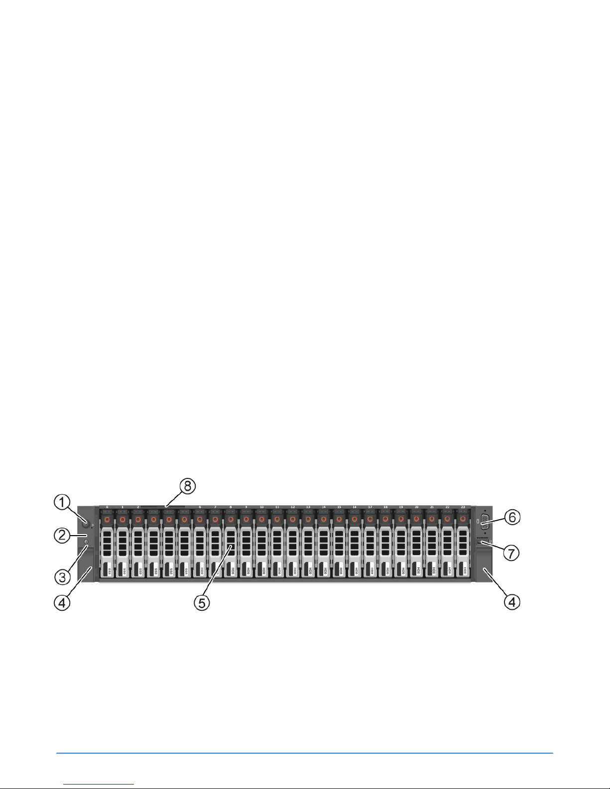
About the front panel components
The front panel of each OmniCube server provides system controls, diagnostic indicators, USB and
video ports, and contains a different number of solid state drives (SSD) and hard disk drives (HDD).
Figure 1: OmniCube CN-5000 front panel
Chapter 1: Hardware overview 8

Figure 2: OmniCube CN-2000 and CN-3000 front panel
Figure 3: OmniCube CN-2200 front panel
Table 1: Front panel component descriptions
Callout Component Description
1 Power button Controls power to the system and indicates whether
there is power to the system. If the indicator is green, the
system is receiving power.
2 Diagnostic indicators Shows hardware error conditions.
3 System identification button System identification button and system identification
connector.
4 Retention latches Locks the enclosure in the rack. You can push a latch to
Chapter 1: Hardware overview 9
The system identification button helps you locate a
system within a rack. If you push the system identification
button on the back panel or the front panel, the system
identification buttons on the front panel and the back
panel flash blue. Push a system identification button a
second time to stop it from flashing.
The system identification connector, located to the right
of the system identification button, connects the optional
system status indicator assembly through the optional
cable management arm.
release the enclosure and slide it out.

Callout Component Description
5 Storage The disk drives have power (top) and activity (bottom)
LED indicators. Labels indicate the type (SAS or SATA)
and capacity of each drive. For rotational drives, the
rotation speed (rpm) is indicated.
The system models contain different drive configurations:
■ CN-5000: Contains 24 2.5" drives. Drives 0 to 5 are
SSDs. Disks 6 to 23 are HDDs.
■ CN-2000 and CN-3000: Contains 12 3.5" drives.
Drives 0 to 3 are SSDs and drives 4 to 11 are HDDs.
■ CN-2200: Contains 10 3.5" drives. Drives 0 and 1 are
SSDs and drives 2 to 9 are HDDs. Drives 10 and 11
are empty.
If you pull the system enclosure from the rack, the drive
numbering scheme is described on a label attached to
the top of the enclosure.
6 Video input Enables you to connect a monitor as part of a keyboard,
video, and mouse (KVM) setup, for local administration.
7 USB connector USB 2.0-compliant connector. Enables you to connect
a USB device, such as a keyboard, as part of a KVM for
local administration.
8 Service tag Provides identification information that you can use when
contacting Customer Support.
About the back panel components
The back panel of an OmniCube server contains the Accelerator, network ports, rear boot drives, and
the power supplies.
Figure 4: Back panel of an OmniCube server with a single CPU
Chapter 1: Hardware overview 10
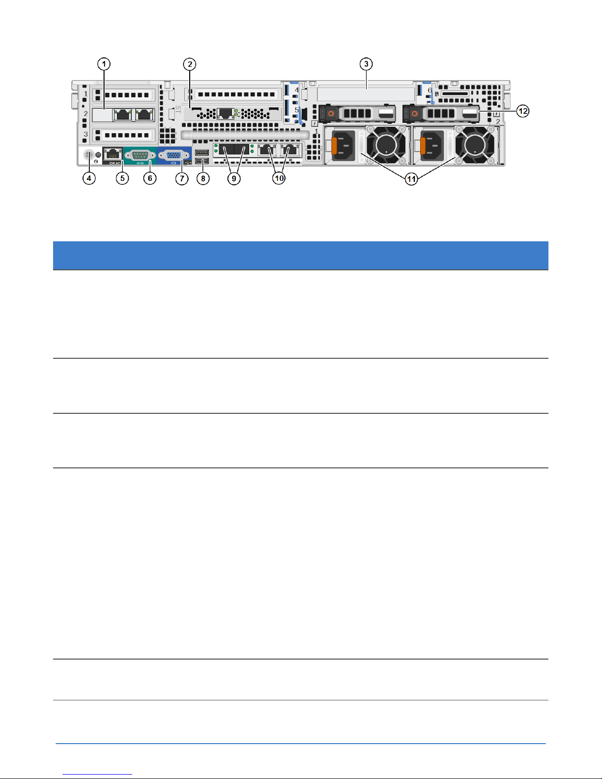
Figure 5: Back panel of an OmniCube server with two CPUs
Table 2: Back panel component descriptions
Callout Component Description
1 Riser 1 Contains PCIe slots 1-3. You can install optional
2x10GbE or 2x1GbE network cards in these slots, as
shown in slot 2, used by guest VMs only.
A system with a single CPU does not contain riser 1. A
plate is installed in place of riser 1.
2 Accelerator Installed in PCIe slot 5 of riser 2, but also occupies slot 4.
The card has two LEDs that continuously glow green to
indicate normal operation.
3 RAID controller RAID Controller for the rear boot drives installed in PCIe
slot 6 of riser 3. The RAID Controller for the front data
disks is a mezzanine card.
4 System identification button System identification button and system identification
connector.
5 IPMI port Dedicated IPMI port for remote, out-of-band, web-based
Chapter 1: Hardware overview 11
The system identification button helps you locate a
system within a rack. If you push the system identification
button on the back panel or the front panel, the system
identification buttons on the front panel and the back
panel flash blue. Push a system identification button a
second time to stop it from flashing.
The system identification connector, located to the right
of the system identification button, connects the optional
system status indicator assembly through the optional
cable management arm.
management.

Callout Component Description
6 Serial port Serial port that you can use to connect a serial device.
7 Video connector Video connector that enables you to connect a monitor or
keyboard, video, monitor (KVM) device.
8 USB connectors Two USB 3.0 compliant ports for connecting USB devices
to the system.
9 10GbE ports Two 10GbE network interfaces, numbered 1 and 2.
Each 10GbE interface has link (top) and activity (bottom)
round LEDs. These interfaces are dedicated to SimpliVity
Storage and Federation networks.
10 1GbE ports Two 1GbE network interfaces, numbered 3 and 4,
from left to right. Each 1GbE interface has link (left)
and activity (right) square LEDs. These interfaces are
dedicated to the Management network and, optionally,
VM traffic.
11 Power supplies Two redundant, 750W or 1100W power supplies
with fans, numbered 1 and 2, from left to right. Each
power supply has a status indicator light in the handle.
Disconnect the power cords before removing a power
supply. Wattage depends on the CPU requirements
(number of cores).
12 Boot drives Two hot-swappable 2.5" hard drives. Reserved for system
use and are not available for user data storage.
Environmental and technical specifications
There are specific environmental and technical specifications for each hardare platform. The
specifications help you when planning the appropriate installation location, environmental conditions,
and resources, such as power and cooling.
Enclosure size and weights
OmniCube servers have specific size dimensions and weights. This information helps you when
planning to install the enclosure in a rack.
Dimension Centimeters Inches
Enclosure width 48.2 17.5
Maximum height 8.73 3.44
Chapter 1: Hardware overview 12

Dimension Centimeters Inches
Maximum depth (from rack
flange)
System Model Kilograms Pounds
CN-2000, CN-2200, CN-3000 32.5 71.5
CN-5000 29.5 65
75.58 29.75
Power and thermal
OmniCube servers have two redundant power supplies with specific power and thermal specifications.
Specification CN-2000 and CN-3000 CN-2200 CN-5000
Current consumption 10A-5A
Supply voltage 100–240VAC
(autoranging). Make
sure each power source
has sufficient electrical
overload protection.
■ 750W: 10A-5A
■ 1100W: 12A-6.5A
100–220VAC
(autoranging). Make
sure each power source
has sufficient electrical
overload protection.
12A-6.5A
100–240VAC
(autoranging). Make
sure each power source
has sufficient electrical
overload protection.
Frequency 50/60Hz 50/60Hz 50/60Hz
Heat dissipation 2843/2891 BTU/hr max
Maximum inrush current 55A 55A 55A
Energy efficiency Energy Star, spec
version 1.0
Power supply efficiency 90-96% efficient (load
dependent)
■ 750W: 2843/2891
BTU/hr max
■ 1100W: 4100 BTU/hr
max
Energy Star, spec
version 1.0
■ 750W: 82-91%
efficient (load
dependent)
■ 1100W: 89-92%
efficient (load
dependent)
4100 BTU/hr max
Energy Star, spec
version 1.0
89-92% efficient (load
dependent)
Chapter 1: Hardware overview 13

Temperature and humidity
OmniCube servers have limits for temperature and humidity under operating and storage conditions.
Specification Description
Humidity and
Temperature
(continuous
operation)
Temperature
(storage)
10°C to 35°C (50°F to 95°F) at 10% to 80% relative humidity with 26°C (78.8°F)
maximum dew point (maximum wet bulb temperature). De-rate maximum
allowable dry bulb temperature at 1°C per 300m above 950m (1°F per 547 ft
above 3117 ft).
-40°C to 65°C (-40°F to 149°F) with a maximum temperature gradation of 20°C
per hour.
Vibration and shock
OmniCube servers have limits for vibration and shock under operating and storage conditions.
Specification Description
Vibration
(operating)
Vibration
(storage)
Shock
(operating)
0.26Grms at 5-350Hz in all orientations.
1.87Grms at 10-500Hz for 15 minutes (all six sides tested).
One shock pulse in the positive z axis (one pulse on each side of the system) of 31G
+/– 5% for +/–10%; in the operational orientation.
Shock
(storage)
Half sine shock on all six sides of 71G +/– 5% with a pulse duration of 2ms +/–10%;
square wave shock on all six sides of 27G with velocity change at 235 in/sec or greater.
Altitude and airborne contaminants
OmniCube servers have limits for altitude and airborne contaminants under operating and storage
conditions.
Specification Description
Altitude (operating) -15.2m to 3048m (–50 ft to 10,000 ft)
Altitude (storage) -15.2m to 12,000m (–50 ft to 39,370 ft)
Contaminant level (operating) Class G1 or lower as defined by ISA-S71.04-1985
Agency compliance standards
OmniCube servers meet agency compliance standards.
An OmniCube host complies with the following standards:
Chapter 1: Hardware overview 14

■ FCC 47 CFR Part 15 Subpart B: 2012
■ EN 55022:2010 COR 2011
■ CISPR 22:2008
■ EN 55024:2010
■ CISPR 24:2010
■ COR 2011
■ VCCIV3:2009
■ ANSI/UL 60950-1, 2nd Edition (2007)
■ CSA C22.2 No. 60950-1 2nd Edition (2007)
■ IEC 60950-1:2005 (2nd Edition); Am 1:2009
■ RoHS EU Directive 2002/95/EC
About hardware upgrades
If you would like to upgrade the server hardware components, contact Customer Support.
Note:
Never install additional options other than those approved for installation by Customer Support. Doing
so will void your warranty and might cause serious server instability and potential data loss.
About firmware revisions
The OmniStack software requires that each supported platform is running a specific firmware revision.
To avoid compatibility issues, contact Customer Support before making any firmware changes.
Note:
If your server, or any management software, has automatic software updates enabled, disable this
feature to avoid installing unsupported firmware revisions.
Chapter 1: Hardware overview 15

Chapter 2: Install the server hardware
This section contains the following topics:
•
About electrostatic discharge
•
Unpack the shipping carton
•
Install the server enclosure in a rack
•
Mount the enclosure in the rails
•
Connect the network cables
•
Connect the power cables
•
Organize the cables
•
Power on the system
•
Attach the OmniCube bezel
Installing the server hardware involves unpacking all hardware components, installing the enclosure in
a rack, connecting the power and network cables, and powering on the server.
About electrostatic discharge
You must protect sensitive hardware from electrostatic discharge (ESD), which can damage electronic
components.
■ Ensure the server hardware is fully grounded at all times to prevent damage from electrostatic
discharge.
■ When not installed in a rack, server hardware must be stored in its original packaging or placed on a
sturdy surface that is protected from electrostatic discharge.
■ When handling server hardware components, always use the electrostatic wrist strap provided, or
use a similar form of ESD protection.
Unpack the shipping carton
You unpack the shipping carton to prepare the system hardware components for installation.
Before you begin
■ The OmniCube servers are heavy. You must have at least one other person to help you lift and
unpack the carton, and SimpliVity recommends the use of a datacenter equipment lift.
■ You have cut the pallet shipping straps, which might have considerable tension, using an appropriate
tool and safety wear.
Chapter 2: Install the server hardware 16
 Loading...