

SimpliVity OmniCube CN-2000, OmniCube CN-5000, OmniCube CN-2200, OmniCube CN-3000 Installation And Maintenance Manual

OmniCube™ CN-Series
Hardware Installation and Maintenance Guide
CN-2000
CN-2200
CN-3000
CN-5000

CN-Series Hardware Installation and Maintenance Guide
SimpliVity, the SimpliVity logo, OmniCube, OmniStack, OmniCube Accelerator, CN-2000, CN-2200, CN3000, CN-5000 and Data Virtualization Platform are trademarks or registered trademarks of SimpliVity
Corporation in the United States and certain other countries. All other trademarks are the property of their
respective owners.
Information in this document is subject to change without notification.
Reproduction in any manner whatsoever without the written permission of SimpliVity Corporation is strictly
forbidden.
© SimpliVity Corporation 2015
Publication Date: 1/16/2015
Part Number: 760-000001 Rev H
2

Table Of Contents
Preface 5
1 - Introduction to the CN-Series Hardware 7
CN-Series Hardware Components 7
Front Panel Description 8
Back Panel Description 10
Environmental and Technical Specifications 11
Enclosure Size and Weights 11
Power and Thermal 12
Temperature and Humidity 12
Vibration and Shock Limits 12
Altitude and Airborne Contaminants 13
Agency Compliance 13
About Hardware Upgrades 13
2 - CN-Series Hardware Installation 15
General Guidelines for Installing Hardware in a Rack 15
Tasks for Installing the Hardware 15
Task 1—Performing the Pre-Installation Tasks 16
Protecting Sensitive Hardware from ESD 16
Unpacking the Shipping Carton 17
Shipping Carton Contents 18
Rail Kit Components 19
Obtaining Hardware That is Not Supplied 20
Rack Requirements 20
Switch Recommendations 21
Understanding the Networks Used in a Federation 22
Task 2—Installing Each CN-Series System in a Rack 23
Mounting the System into the Rails 23
Task 3—Connecting the Power Cables 25
Task 4—Connecting the Network Cables 26
Organizing Cables 27
Task 5—Configuring IPMI for Remote Management 27
Connecting to IPMI and Launching the Virtual Console 30
Task 6—Powering on the System 30
Attaching and Removing the Bezel 31
3 - VMware ESXi Configuration 33
Accessing VMware ESXi Through the IPMI Virtual Console 33
Verifying ESXi Shell and SSH are Enabled 34
Configuring the Management Network Adapters 34
Configuring a VLAN 35
Configuring the Management Network IP Settings 36
Configuring the DNS Settings 37
Configuring a DNS Suffix 38
4 - Basic Troubleshooting 39
About Diagnostic Indicators 39
3

CN-Series Hardware Installation and Maintenance Guide
Viewing events or alarms in the vSphere Client 40
Drive Monitoring 40
Viewing Drive Status in the vSphere Client 41
Power Supply Monitoring 42
Viewing Power Supply Status in the vSphere Client 42
Accelerator Card Monitoring 43
Viewing Accelerator Card Status in the vSphere Client 44
Accelerator Card is Not Detected 44
Reverting an Accelerator Card to its Backup Firmware 45
Network Interface Monitoring 45
Viewing Network Interface Status in the vSphere Client 46
Ports Required for Network Communication 46
5 - Drive Maintenance 49
Guidelines for Maintaining Drives 49
Removing a Drive 50
Installing a Drive 51
6 - Power Supply Maintenance 53
Guidelines for Maintaining Power Supplies 53
Removing a Power Supply 53
Installing a Power Supply 54
Appendix A - Network Configuration Options 57
10GbE-Only Network Configuration 57
Direct-Connected Storage Network Configuration 58
Switch-Connected Storage Network Configuration 59
Index 61
4

Preface
This document introduces the CN-Series system, describes the hardware specifications and requirements,
and provides instructions about installing and maintaining the hardware.
Overview of the CN-Series system
The foundation of the SimpliVity architecture is two or more high-performance and highly-available
CN-Series systems. After installing the hardware in a rack and connecting power and network cables, you
can create a datacenter within vCenter™ Server and configure the OmniCubeTMsystems into an OmniCube
Global Federation.
Each CN-Series system (configured as an OmniCube) provides computing, storage, networking, and other
resources to the virtual machines (VMs) in the Federation. As your capacity and performance needs
increase, you can add more OmniCube systems for easy, on-demand scalability, with no disruption to users.
This guide applies to the following CN-Series models:
• CN-2000
• CN-2200
• CN-3000
• CN-5000
See the OmniCube Release Notes for configuration and usage constraints.
Audience
The intended audience for this document includes individuals who want to learn more about the CN-Series
system hardware, and individuals who are responsible for installing and maintaining the hardware.
To perform the tasks described in this document, you should know:
• How to install server hardware in a rack.
• The power configuration in the installation location.
• The network configuration in the installation location.
• The cooling capacity of the installation location.
Technical Support and Customer Service
5

CN-Series Hardware Installation and Maintenance Guide Preface
Support services from SimpliVity are available to answer your questions about the CN-Series system. SimpliVity provides online and telephone-based support services. Availability varies by country and product, and
some services might not be available in your area. You can configure Phone Home support to automatically
notify support about significant events.
Ensure you have the CN-Series system serial number, which is recorded on the Service Tag (a pull out card)
located:
• CN-2000, CN-2200, and CN-3000—Under drive 2 on the front panel.
• CN-5000—Above drives 3 & 4 on the front panel.
Contact Support
To contact SimpliVity support, visit the SimpliVity Web site at www.SimpliVity.com/support.
US:
1-855-SVT-SERVICE
(1-855-788-7378)
International:
1-508-536-4151
Email: support@simplivity.com
6
1 - Introduction to the CN-Series Hardware
This section contains information about the CN-Series system hardware components and describes the
system specifications.
CN-Series Hardware Components
The minimum Federation configuration consists of a pair of high-performance and highly-available
CN-Series systems. After you install the hardware, you can create a Federation within vCenter Server and
configure each CN-Series system as a Federation OmniCube. See the OmniCube Release Notes for
information about configuration limits.
Each OmniCube provides computing, storage, and other resources to the virtual machines (VMs) in the
Federation. When you need more capacity or performance, you can add more OmniCube systems to the
Federation, with no disruption to users.
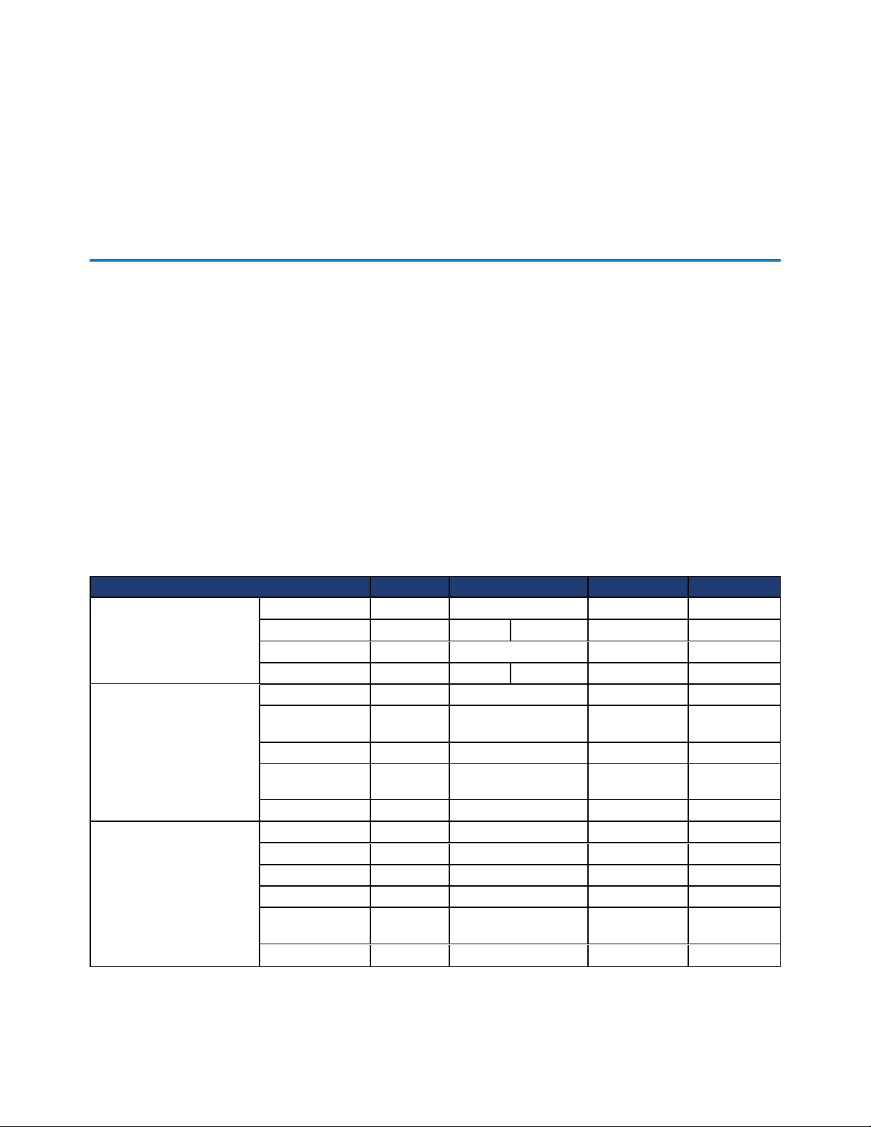
The following table describes the components of the 2U CN-Series system models.
Component CN-2000 CN-2200 CN-3000 CN-5000
CPU
Front SSD Drives
Front HDD Drives
Model Intel Xeon
CPU Count 1 1 2 2 2
Speed, GHz 2.4 or 2.6 2.4 or 2.6 2.5 2.7
Cores 6 or 8 8 8, 10, or 12 12 or 24 12 or 24
Quantity 4
Capacity 100 GB 400 GB
Interface SATA SATA SATA SATA
Dimension
RAID Type RAID5 RAID 1 RAID 5 RAID 5
Quantity 8 8 8 18
Capacity 1 TB 1 TB 3 TB 1.2 TB
Interface SATA SATA SAS SAS
RPM 7,200 7,200 7,200 10,000
Dimension
RAID Type RAID 6 RAID 6 RAID 6 RAID 6
2.5" (3.5"
carrier)
3.5" (3.5"
carrier)
Intel Xeon
2
2.5" (3.5" carrier) 2.5" (3.5"
3.5" (3.5" carrier) 3.5" (3.5"
Intel Xeon
4
400 GB or 800GB400 GB or
carrier)
carrier)
Intel Xeon
6
800 GB
2.5"
2.5"
7
CN-Series Hardware Installation and Maintenance Guide CN-Series Hardware Components
6
5
4
11
2
3
4
8
7
Component CN-2000 CN-2200 CN-3000 CN-5000
Quantity 2 2 2 2
Capacity 300 GB 300 GB 300 GB 300 GB
Rear HDDDrives
Memory 1333 MHz 128 GB
Power Supply
Network Interfaces
Deduplication and
Compression
Remote System
Management
Interface SATA SATA SAS SAS
Dimension 2.5" 2.5" 2.5" 2.5"
RPM 10,000 10,000 10,000 10,000
RAID Type RAID 1 RAID 1 RAID 1 RAID 1
128 GB
min 512 GB
max
Hot swap,
integrated fans
Embedded
VM Network
[optional]
OmniCube Accelerator V2
IPMI processor and network port for remote, Web-based management.
2 x 750W
2 x 10GbE and 2 x 1GbE
N/A 2 x 10GbE or 2 x 1GbE
2 x
750W
256 GB
min - 512
GB max
2 x 750W
(8 core) or
2 x 1100W
(10 or 12
core)
128 GB min 512 GB max
2 x 750W (16
core) or 2 x
1100W (24
core)
1
768 GB
2 x 1100W
1
Contact your SimpliVity sales representative to learn about the vendor-specific interface cards currently
supported for your platform.
Front Panel Description
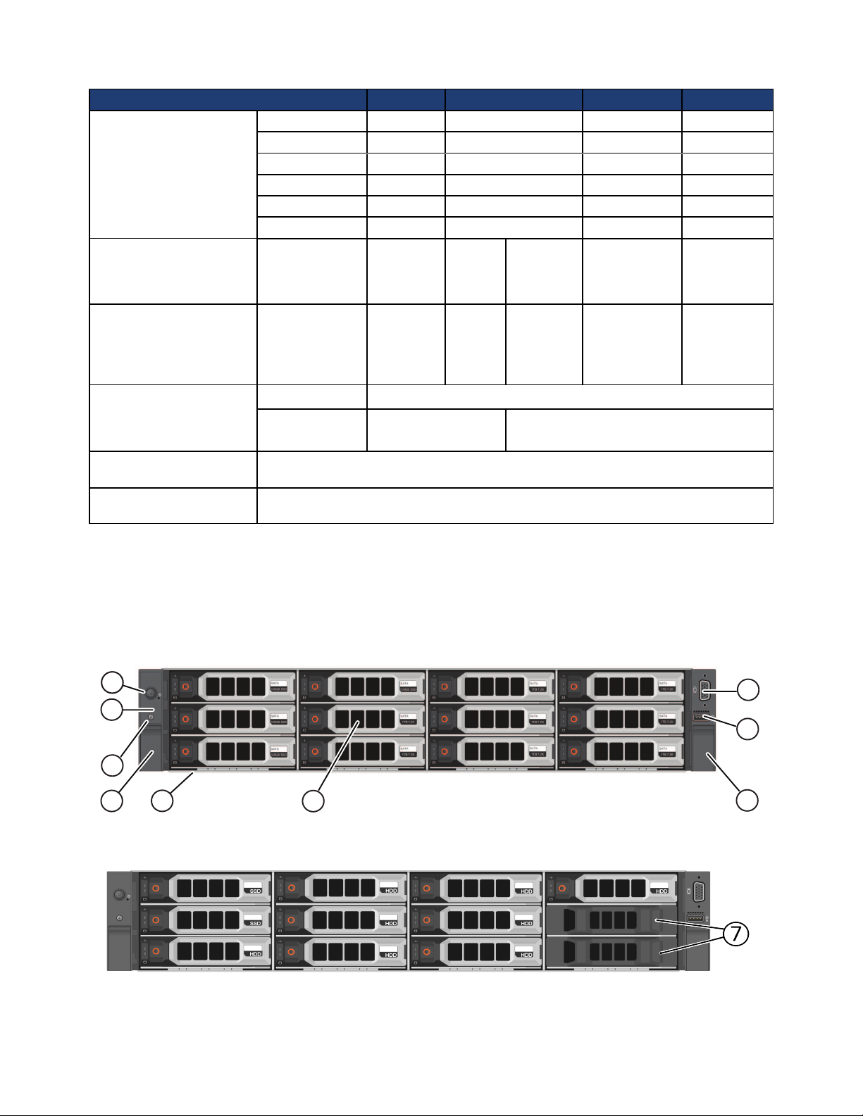
The following image shows the front panel of a CN-2000 or CN-3000 with the bezel removed.
The following image shows the front panel of a CN-2200 with the bezel removed.
The following table describes the components of the front panels above.
8
CN-Series Hardware Installation and Maintenance Guide CN-Series Hardware Components
6
5
4
11
2
3
4
8
7
Callout Component Description
1 Power button Controls power to the CN-Series system and indicates whether there is power present.
If the indicator is green, the CN-Series system is receiving power.
2 Diagnostic
indicators
Shows CN-Series system hardware error conditions.
3 System
identification
button
4 Retention latches Locks the CN-Series system enclosure in the rack, push to slide the enclosure out.
5 USB connector USB 2.0-compliant connector. Enables you to connect a USB device such as a
6 Video input Enables you to connect a monitor as part of a KVM for local administration.
7 Storage 3.5" disk drives with power (top) and activity (bottom) LED indicators. Labels
8 Service tab (pull-
out)
Enables you to find a CN-Series system within a rack.
Push the system identification button on the front panel or the back panel. The
system identification buttons on the front panel and the back panel flash blue until
you push one of the buttons again.
keyboard as part of a KVM, for local administration. You can also insert a flash drive
when upgrading system software.
indicate the type (SAS or SATA) and capacity of each drive. For rotational drives,
the rotation speed (rpm) is indicated. The CN-2000 and CN-3000 have 12 drives. The
CN-2200 has 10 drives.
For the CN-2000 or CN-3000, the drives are numbered from 0 to 11, top to bottom,
and left to right. Drives 0 to 3 are SSDs and drives 4 to 11 are HDDs.
For the CN-2200, the drives are numbered from 0 to 9, top to bottom, and left to
right. Drives 0 and 1 are SSDs and drives 2 to 9 are HDDs. Drives 10 and 11 are
empty.
If you pull the CN-Series system enclosure from the rack, the drive numbering
scheme is described on a label attached to the top of the enclosure.
Provides identification information that might be required during a technical support
session.
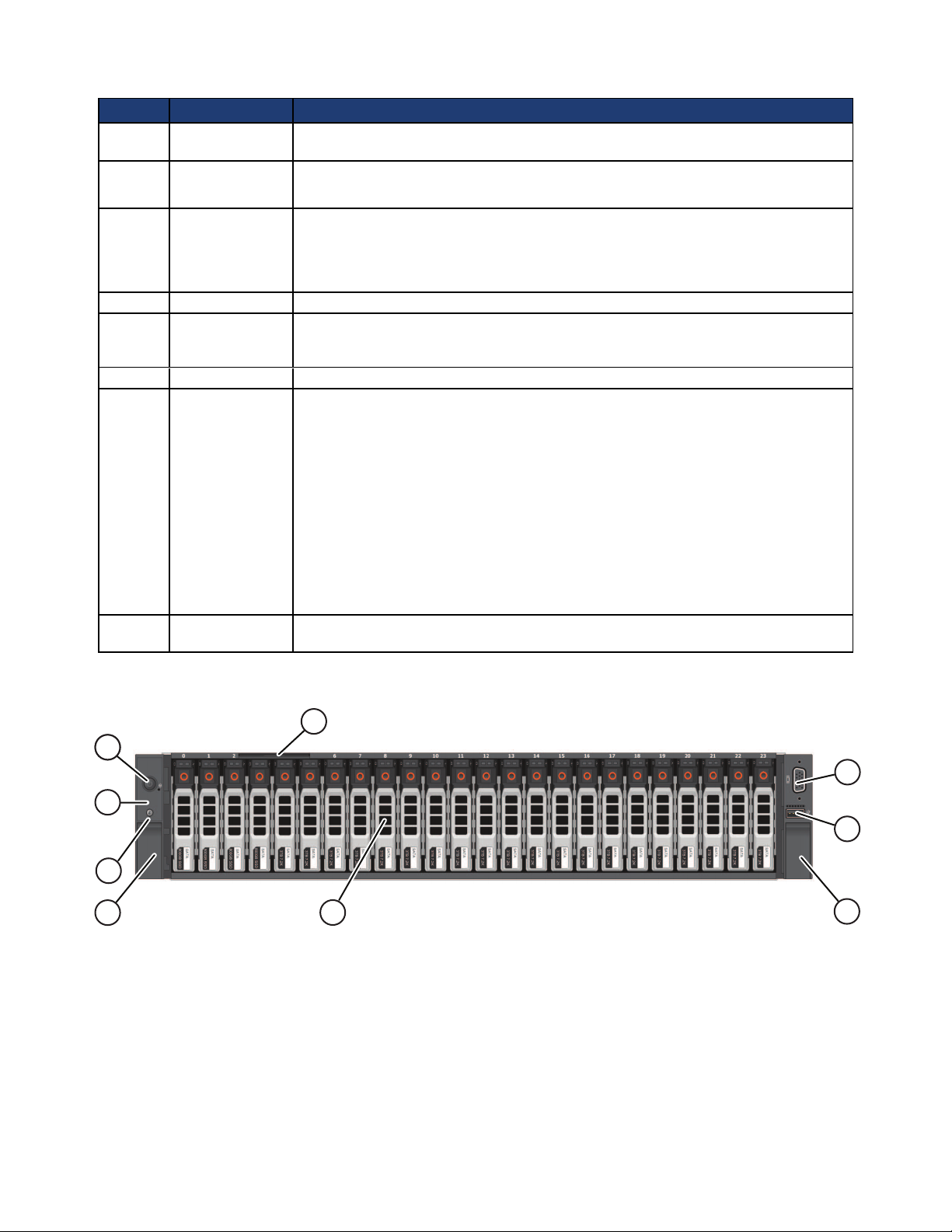
The following image shows the front panel of a CN-5000 with the bezel removed.
The following table describes the components of the CN-5000 front panel.
9
CN-Series Hardware Installation and Maintenance Guide CN-Series Hardware Components
Callout Component Description
1 Power button Controls power to the CN-Series system and indicates whether there is power to the
CN-Series system. If the indicator is green, the CN-Series system is receiving power.
2 Diagnostic
indicators
Show CN-Series system hardware error conditions.
3 System
identification
button
4 Retention latches Lock the CN-Series system enclosure in the rack, push to slide the enclosure out.
5 USB connector USB 2.0-compliant connector. Enables you to connect a USB device such as a
6 Video Input Enables you to connect a monitor as part of a KVM, for local administration.
7 Storage 24 drives, size 2.5", with power (right) and activity (left) LED indicators.
8 Service tab Provides identification information that might be required during a technical support
Finds a CN-Series system within a rack.
Push the system identification button on the front panel (or the back panel). The
system identification buttons on the front panel and the back panel flash blue until
you push one of the buttons again.
keyboard as part of a KVM for local administration.
Disks are numbered from 0 to 23, left to right. Disks 0 to 5 are SSDs. Disks 6 to 23
are HDDs. If you pull the CN-Series system enclosure from the rack, the disk
numbering scheme appears on a label attached to the top of the enclosure.
session.
Related Topics
About Diagnostic Indicators on page 39
Drive Monitoring on page 40
Technical Support and Customer Service on page 5
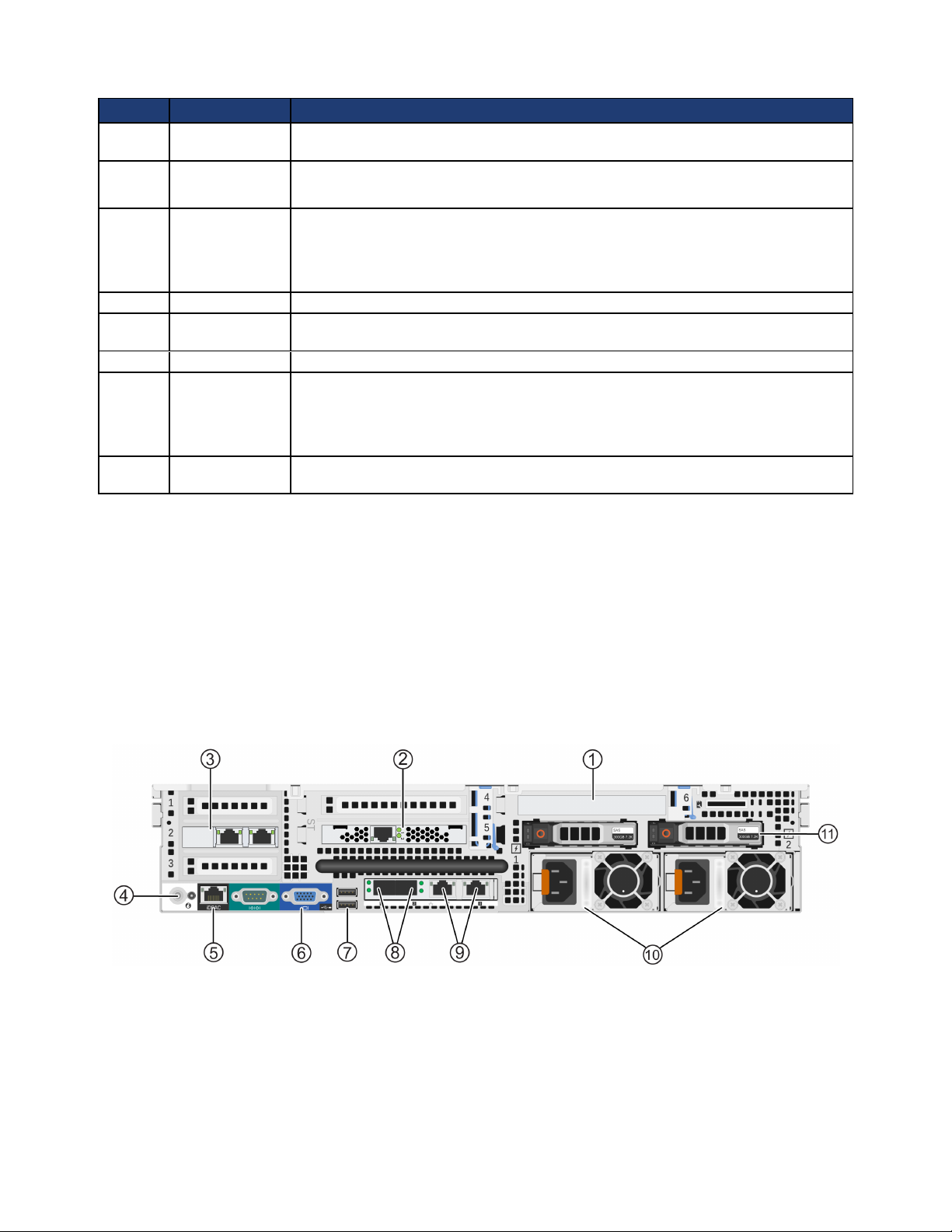
Back Panel Description
The following image shows the back panel of all 2U CN-Series systems.
The following table describes the components of the back panel.
10
CN-Series Hardware Installation and Maintenance Guide Environmental and Technical Specifications
Callout Description
1 Slot 6 - PERC H310 Disk controller.
2 OmniCube Accelerator™ installed in slot 5 of riser 2 with two LEDs.
Both LEDs glow continuously to indicate normal operation.
3 Optional 2x10GbE or 2x1GbE network card, used by guest VMs only and available only in the CN-
2200 with two CPUs, CN-3000, and CN-5000.
4 System identification button and system identification connector.
The system identification button helps locate a CN-Series system within a rack. If you push the system
identification button on the back panel or the front panel, the system identification buttons on the front
panel and the back panel flash blue. Push a system identification button a second time to stop it from
flashing.
The system identification connector, located to the right of the system identification button, connects the
optional system status indicator assembly through the optional cable management arm.
5 Dedicated IPMI port for remote Web-based management.
6 Video connector that enables you to connect a monitor or KVM.
7 Two USB connectors that are USB 2.0-compliant. Enables you to connect a monitor or KVM or insert a
flash drive for software upgrades.
8 Two 10GbE network interfaces, numbered 1 and 2. Each 10GbE interface has link (top) and activity
(bottom) round LEDs. These interfaces are dedicated to SimpliVity Storage and Federation networks.
9 Two 1GbE network interfaces, numbered 3 and 4, from left to right. Each 1GbE interface has link (left)
and activity (right) square LEDs. These interfaces are dedicated to SimpliVity Storage and Federation
networks.
10 Two redundant, 750W or 1100W power supplies with fans, numbered 1 and 2, from left to right. Each
power supply has a status indicator light in the handle. Disconnect the power cords before removing a
power supply. Wattage depends on the CPU requirements (number of cores).
11 Two hot-swappable 2.5" hard drives. Reserved for system use and are not available for user data storage.
Related Topics
Network Interface Monitoring on page 45
Accelerator Card Monitoring on page 43
Power Supply Monitoring on page 42
Environmental and Technical Specifications
The following sections describe the environmental and technical specifications for a CN-Series system. Use
this information to determine whether your intended installation location can provide the appropriate
environmental conditions and resources such as power and cooling.
Enclosure Size and Weights
The following table describes the dimensions of 2U CN-Series system models including:
• CN-2000
• CN-2200
• CN-3000
11
CN-Series Hardware Installation and Maintenance Guide Environmental and Technical Specifications
• CN-5000
Specification MM Inches
2U form factor 88.9 3.50
Maximum width (rack flange) 482.4 19.00
Enclosure width 444.0 17.50
Maximum height 87.3 3.43
Maximum depth (from rack flange) 28.50 723.0 28.5
The following table describes the weight of all CN-Series system models with all storage drives installed.
Specification Kg Lbs
CN-2000, CN-2200, and CN-3000 32.5 71.5
CN-5000 29.5 65.0
Power and Thermal
The following table describes the power and thermal specification for a CN-Series system with two
redundant power supplies.
Specification CN-2000, CN-2200, and CN-3000 CN-5000
Current consumption 10A–5A 12A–6.5A
Supply voltage 100–240VAC (auto-ranging). Make sure
each power source has sufficient electrical
overload protection.
Frequency 50/60Hz 50/60Hz
Heat dissipation (BTU/hr
max.)
Maximum inrush current 55A 55A
Energy efficiency Energy Star, spec version 1.0 Energy Star, spec version 1.0
Power supply efficiency 90-96% efficient (load dependent) 89-92% efficient (load dependent)
2843 / 2891 BTU/hr max 4100 BTU/hr max
100–240VAC (auto-ranging). Make sure
each power source has sufficient electrical
overload protection.
Temperature and Humidity
The following table describes the temperature and humidity limits for a CN-Series system.
Specification Maximum System Limits
Humidity and Temperature
(continuous operation)
Temperature (storage) -40°C to 65°C (-40°F to 149°F) with a maximum temperature gradation of 20°C per
10°C to 35°C (50°F to 95°F) at 10% to 80% relative humidity with 26°C (78.8°F)
maximum dew point (maximum wet bulb temperature). De-rate maximum allowable
dry bulb temperature at 1°C per 300m above 950m (1°F per 547 ft above 3117 ft).
hour.
Vibration and Shock Limits
The following table describes the vibration and shock maximum limit specifications for a CN-Series system.
12
CN-Series Hardware Installation and Maintenance Guide About Hardware Upgrades
Specification Maximum System Limit
Vibration (operating) 0.26Grms at 5-350Hz in all orientations.
Vibration (storage) 1.87Grms at 10-500Hz for 15 minutes (all six sides tested).
Shock (operating) One shock pulse in the positive z axis (one pulse on each side of the system) of 31G +/–
5% for +/–10%; in the operational orientation.
Shock (storage) Half sine shock on all six sides of 71G +/– 5% with a pulse duration of 2ms +/–10%;
square wave shock on all six sides of 27G with velocity change at 235 in/sec or greater.
Altitude and Airborne Contaminants
The following table describes the maximum altitude and airborne contaminants specifications for all
CN-Series system models.
Specification Maximum System Limit
Altitude (operating) -15.2m to 3048m (–50 ft to 10,000 ft)
Altitude (storage) -15.2m to 12,000m (–50 ft to 39,370 ft)
Contaminant level (operating) Class G1 or lower as defined by ISA-S71.04-1985
Agency Compliance
The following table lists agency compliance for all CN-Series systems.
Standard
FCC47 CFR Part 15 Subpart B: 2012
EN 55022:2010 COR 2011
CISPR 22:2008
EN 55024:2010
CISPR 24:2010
COR 2011
VCCIV3:2009
ANSI/UL 60950-1, 2nd Edition (2007)
CSA C22.2 No. 60950-1 2nd Edition (2007)
IEC 60950-1:2005 (2nd Edition); Am 1:2009
RoHS EU Directive 2002/95/EC
About Hardware Upgrades
If you would like to upgrade the system hardware components, contact SimpliVity Customer Service.
Warning: Never install additional options in the other than those approved for installation by
SimpliVity. Doing so will void your warranty and might cause serious system instability and
potential data loss.
13

14

2 - CN-Series Hardware Installation
This section describes how to install a CN-Series system for a minimum Federation that contains two
OmniCube systems. As your storage and performance needs increase, you can add more OmniCube systems
to a Federation.
General Guidelines for Installing Hardware in a Rack
SimpliVity recommends that you install the hardware in a rack according to the following guidelines:
• Follow all safety guidelines stated in the rack's documentation, particularly when installing components
into the locations at the top of the rack.
• Make sure the rack meets the requirements.
• Install systems in the same rack when possible.
• Install systems in a rack starting from the bottom of the rack.
• Always install a CN-Series systemin a horizontal position, or you void your warranty and support
contract.
Related Topics
Rack Requirements on page 20
Task 2—Installing Each CN-Series System in a Rack on page 23
Tasks for Installing the Hardware
After you install the CN-Series system in a rack and connect power and network cables, you can create a
datacenter within vCenter Server and deploy each CN-Series system as an OmniCube in a Federation.
Complete these tasks to install the hardware for a Federation containing two OmniCube systems:
• Task 1—Performing the Pre-Installation Tasks on page 16
• Task 2—Installing Each CN-Series System in a Rack on page 23
• Task 3—Connecting the Power Cables on page 25
• Task 4—Connecting the Network Cables on page 26
• Task 5—Configuring IPMI for Remote Management on page 27
• Task 6—Powering on the System on page 30
15

CN-Series Hardware Installation and Maintenance Guide Task 1—Performing the Pre-Installation Tasks
After completing the installation:
• Organizing the power and network cables at the back of each CN-Series system.
• Attaching the bezel to the front of each system.
• Configuring VMware ESXi settings.
• Using the VMware vSphere Client to deploy each system as an OmniCube, as explained in the
OmniCube for vSphere Client Administrator Guide .
Related Topics
Attaching and Removing the Bezel on page 31
Organizing Cables on page 27
VMware ESXi Configuration on page 33
Task 1—Performing the Pre-Installation Tasks
Perform the following tasks before beginning the hardware installation.
• Ensure the installation location meets environmental, power, and other requirements.
• Learn how to protect sensitive hardware.
• Unpack the shipping box and make sure the shipping box contents are complete.
• Gather the hardware needed for the installation, but not provided in the shipping box.
• Learn about the networks used in a Federation and plan your network configuration.
Related Topics
Environmental and Technical Specifications on page 11
Obtaining Hardware That is Not Supplied on page 20
Protecting Sensitive Hardware from ESD on page 16
Shipping Carton Contents on page 18
Understanding the Networks Used in a Federation on page 22
Unpacking the Shipping Carton on page 17
Protecting Sensitive Hardware from ESD
You must protect sensitive hardware from electrostatic discharge.
Make sure the system hardware is fully grounded at all times to prevent damage from electrostatic
discharge. When not installed in a rack, system hardware must be stored in its original packaging or placed
on a sturdy surface that is protected from electrostatic discharge.
16
CN-Series Hardware Installation and Maintenance Guide Task 1—Performing the Pre-Installation Tasks
When handling system hardware components, always use the electrostatic wrist strap provided, or use a
similar form of ESD protection.
Unpacking the Shipping Carton
When unpacking the shipping carton, be aware of the following:
• The systems are heavy. Two or three people are required to lift and unpack the cartons and SimpliVity
recommends the use of a datacenter equipment lift.
• Pallet shipping straps might have considerable tension. Cut these with an appropriate tool and use
appropriate safety wear.
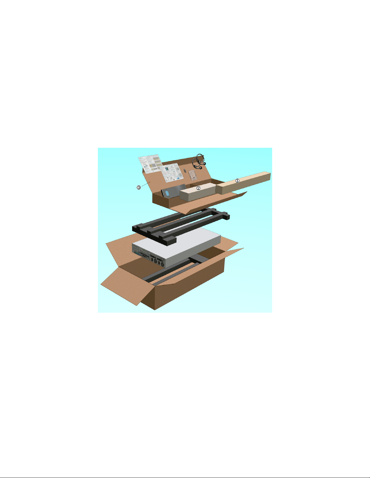
The following image shows the carton contents for a 2U model.
To unpack the shipping carton:
1. Remove the shrink wrap from the palleted cartons and carefully cut any straps that hold the cartons to
the pallet.
2. To orient the carton for ease of unpacking and racking, locate the black circle printed on the side of the
carton. This is the front of the CN-Series system enclosure.
3. Use a boxcutter to cut the sealing tape. Be careful that you do not cut into the carton. Retain the carton
and packaging in case you need to return the system.
4. Remove the rail kit (callout 1), which contains the rails and the installation instructions.
17
CN-Series Hardware Installation and Maintenance Guide Task 1—Performing the Pre-Installation Tasks
5. Remove the cable management arm (CMA) kit, (callout 2) which contains the CMA assembly, a signal
LED extension cable, and the installation instructions. Do not open this box until the end of the
installation procedure, when you are ready to organize the system cables.
6. Remove the accessory pack (callout 3), which contains:
– the bezel
– power and network cables
– software and documentation flash drive
– QuickStart posters and international Product Information Guide.
7. If you are not ready to install the CN-Series system in a rack, keep the CN-Series system in the shipping
box or place the CN-Series system on a sturdy surface that is protected from electrostatic discharge.
Verify that the contents of the shipping box are complete.
Related Topics
Shipping Carton Contents on page 18
Shipping Carton Contents
After unpacking the CN-Series system shipping carton, ensure you have all the items described in the
following table. Additional hardware not supplied in the shipping carton is also required.
Part Description
CN-Series system Provides processing power and storage capacity.
Bezel Protects disk drives in the CN-Series system front panel.
Two power cords
3-meter SFP+ Direct
Attach cable
Sliding rail kit Contains the left and the right rails, two hook and loop straps, and detailed installation
Cable management arm
kit
USB flash drive Contains the SimpliVity vSphere™ Extension and SimpliVity Arbiter software and
Printed Documentation
• 15amp NEMA 5-15P to C13 power cord. Connects a CN-Series system to power.
• 15amp C14 to C13 power cord. Connects a CN-Series system to power.
Connects a 10GbE interface on one CN-Series system to a 10GbE interface on another
CN-Series system or to a network switch.
Depending on your network configuration and the distance between the CN-Series system
or the distance between a CN-Series system and a switch, you might need different or
additional cables.
documentation.
Contains the cable management arm (CMA) assembly and installation documentation.
recovery software for resetting the system. PDF copies of the following documents are
provided:
• OmniCube Hardware Installation and Maintenance Guide
• OmniCube for vSphere Client Administrator Guide
• OmniCube Command Reference
• Hardware Installation QuickStart
• Software Configuration QuickStart
• OmniCube Release Notes
• Hardware Installation QuickStart
• Software Configuration QuickStart
• Product Information Guide (safety and regulatory notices)
Related Topics
18
CN-Series Hardware Installation and Maintenance Guide Task 1—Performing the Pre-Installation Tasks
LEFT
Front
Obtaining Hardware That is Not Supplied on page 20
Rail Kit Components
The rail kit contains these items:
• Two sliding rail tool-less (fasteners optional) assemblies, left and right.
• Two hook and loop cable straps.
• Documentation.
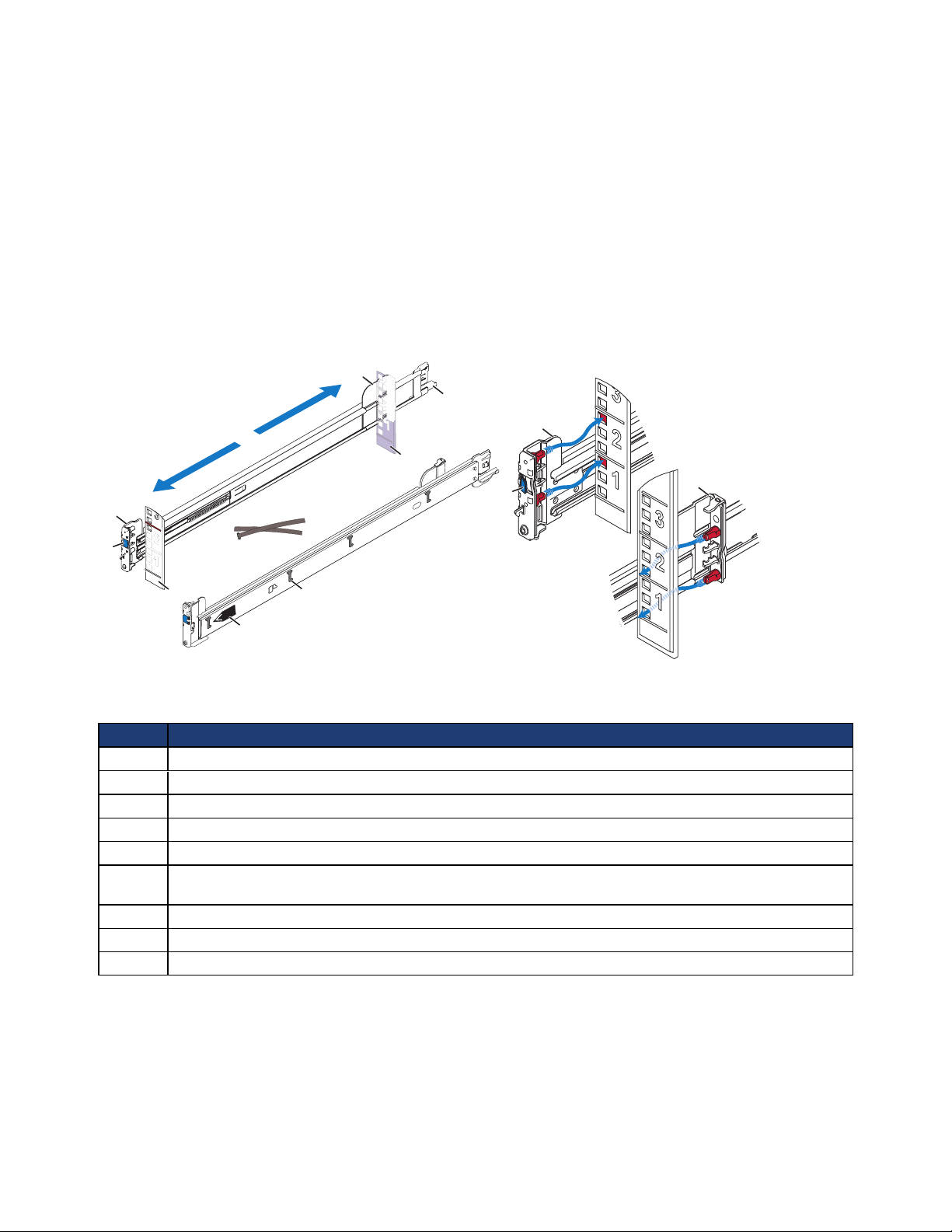
The following image shows the rail kit components.
The following table describes the rail kit components in the above image.
Callout Component
1 Front rail bracket—secures the rail to a rack column, using holes at position 1 and 4 in the 2U space.
2 Rear rail bracket—secures the rail to a rack column, using holes at position 3 and 6 in the 2U space.
3 Rack depth adjustment.
4 Blue, spring-loaded latch—secures the rails in place.
5 Rack columns (posts).
6 Cable management arm mount point or, if you do not use the cable management arm, cable fastening
point.
7 Cable straps.
8 J-shaped retaining slots (4) for the pins on the side of the server (shown on left rail).
9 Label identifying the left or right rail (shown on left rail).
Related Topics
Task 2—Installing Each CN-Series System in a Rack on page 23
19
CN-Series Hardware Installation and Maintenance Guide Task 1—Performing the Pre-Installation Tasks
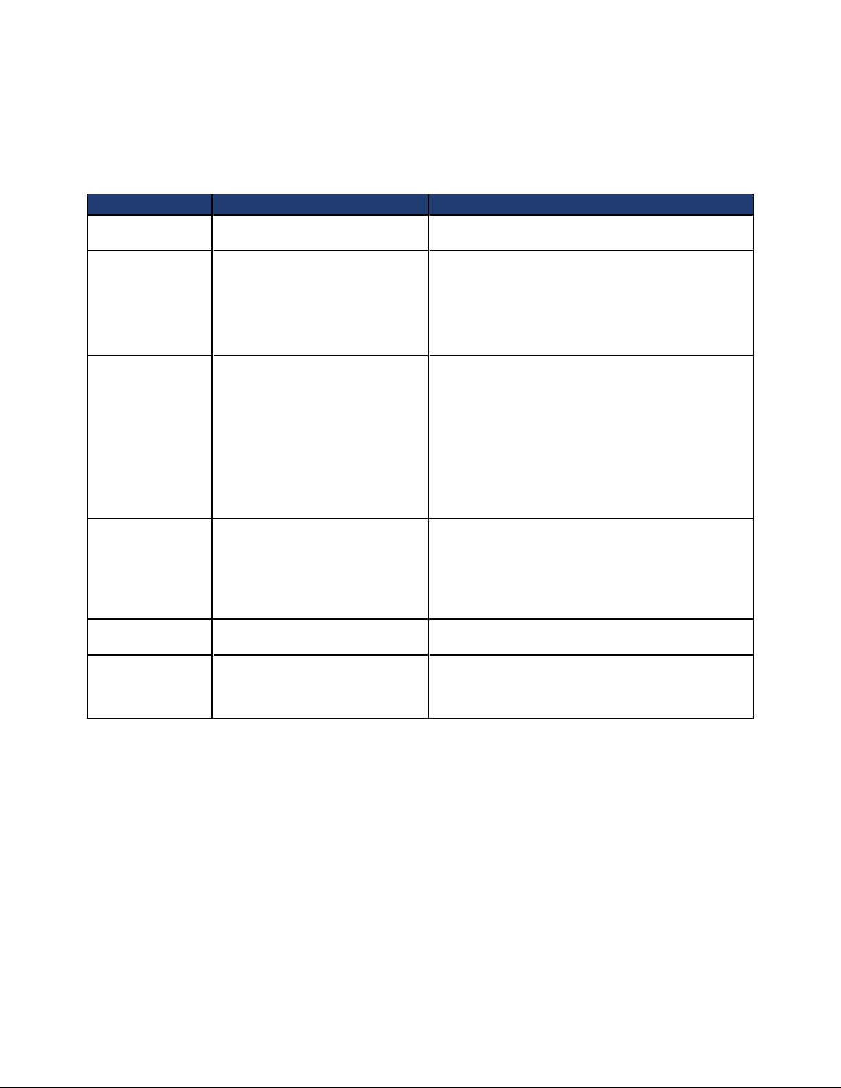
Obtaining Hardware That is Not Supplied
You must provide additional hardware that is specific to your environment and not included in the shipping
carton. Some of the necessary hardware depends on your network configuration. The following table lists the
additional items might be required for installing the hardware:
Hardware Description Application
Rack 19 inch (48.3 cm), four-post, tool-
less rack.
1GbE Data Cables For each CN-Series system, two
Category 5E or Category 6 cables
with RJ45 connectors.
(An optional third cable is required
to use the IPMI port for remote
console access.)
10GbE Data Cables For each CN-Series system, one of
the following SFP+ cable sets:
• One or two SFP+ Direct Attach
cables of sufficient length
(maximum 10 meters).
• One or two 10GbE SFP+ fiber
transceivers and 10GbE Fiber
Optic cables, LC/LC,Multi Mode,
Duplex (50/125 Type).
Additional Guest
VMNetwork
Cables (Optional)
Redundant
Network Switches
Redundant
Uninterruptible
Power Supply
(UPS)
• 1GbE Guest VM network card - 1
or 2 Category 5E or Category 6
cables.
• 10GbE Guest VM network card 1 or 2 SFP+ Direct Attach or 1 or
2 10GbE SFP+ fiber transceivers
and 10GbE Fiber Optic cables.
Required number of switches. Connects devices to a network. The number of
Required number of UPS devices. Provides temporary power to the CN-Series system in
Provides easy access to CN-Series system hardware in
your computing environment.
Connect the 1GbE network interfaces on a CN-Series
system to a 1GbE switch. This is required only if you
are connecting the 1GbE network interfaces on each
CN-Series system.
Connects a 10GbE network interface on a CN-Series
system to a 10GbE network interface on another
CN-Series system or to a switch.The number and type
of cables you need depends on your network
configuration and the distance between CN-Series
systems or the distance between a CN-Series systems
and a switch.
If you are using the direct-connected configuration and
the two CN-Series systems are within 2 meters of each
other, you do not need additional cables.
If your CN-Series system contains an optional Guest
VM network card, you will also need these cables.
switches depends on your network configuration.
the event of a complete power outage.
Related Topics
Switch Recommendations on page 21
Direct-Connected Storage Network Configuration on page 58
Switch-Connected Storage Network Configuration on page 59
Understanding the Networks Used in a Federation on page 22
Rack Requirements
Each CN-Series system ships with the following racking components:
20
 Loading...