

SimpliVity CN-2200, CN-2000, CN-3000, CN-5000 Hardware Installation And Maintenance Manual

OmniCube™ CN-Series
Hardware Installation and Maintenance Guide
OmniStack™ Software Version 2.1.5

OmniCube CN-Series Hardware Installation and Maintenance Guide
SimpliVity, the SimpliVity logo, OmniCube, OmniStack, OmniCube Accelerator, CN-2000, CN-2200, CN-3000,
CN-5000 and Data Virtualization Platform are trademarks or registered trademarks of SimpliVity Corporation in the
United States and certain other countries. All other trademarks are the property of their respective owners.
Information in this document is subject to change without notification.
Reproduction in any manner whatsoever without the written permission of SimpliVity is strictly forbidden.
© SimpliVity Corporation 2014
Publication Date: 10/28/2014
Part Number: 760-000001 Rev G
2

3

Table Of Contents
Preface 6
1 - Introduction to the CN-Series Hardware 8
CN-Series Hardware Components 8
CN-Series Enclosure Front Panel 9
CN-Series Enclosure Back Panel 11
CN-Series Enclosure Interior 13
CN-Series Environmental and Technical Specifications 14
Enclosure Size and Weights 14
Power and Thermal 14
Temperature and Humidity 15
Vibration and Shock Limits 15
Altitude and Airborne Contaminants 15
Agency Compliance 16
2 - Installing the CN-Series System 18
General Guidelines for Installing Hardware in a Rack 18
Tasks for Installing the Hardware 18
Task 1—Perform the Pre-Installation Tasks 19
Protecting Sensitive Hardware from ESD 19
Unpacking the Shipping Carton 19
Obtaining Hardware That Is Not Supplied 21
Understanding the Networks Used in a Federation 23
Task 2—Install the CN-Series Enclosure in a Rack 24
Task 3—Connect the Power Cables 25
Task 4—Connect the Network Cables 26
Minimum (10GbE-Only) OmniCube Network Configuration 27
Minimum Configuration for a Direct-Connected Storage Network 28
Minimum Configuration for a Switch-Connected Storage Network 29
Organizing Cables 30
Task 5—Configure IPMI for Remote Management 30
Task 6—Configuring the ESXi Host 33
Task 7—Turn On Power 35
Attaching and Removing the Bezel 36
3 - Basic Maintenance and Troubleshooting 38
Diagnostic Indicators 38
Identifying Drive Problems 39
Identifying OmniCube Accelerator Problems 41
Identifying Network Interface Problems 44
Ports Required for Network Communication 45
Identifying Power Supply Problems 45
Opening and Closing the Enclosure Cover 46
Prerequisites for Opening the Enclosure Cover 46
Opening the CN-Series 2U Enclosure Cover 46
Closing the CN-Series 2U Enclosure Cover 48
Upgrading Hardware 48
4

OmniCube CN-Series Hardware Installation and Maintenance Guide
Appendix A - Installing and Using the Rail Kit 50
Rail Kit Components 50
Installing the Rail Kit 51
Mounting the Enclosure into the Rails 52
Index 54
5

Preface
This document introduces the CN-Series system, describes the hardware specifications and requirements,
and provides instructions about installing and maintaining the hardware.
Overview of the CN-Series system
The foundation of the SimpliVity architecture is two or more high-performance and highly-available
CN-Series systems. After installing the hardware in a rack and connecting power and network cables, you
can create a datacenter within vCenter™ Server and configure the OmniCubeTMsystems into an OmniCube
Global Federation.
Each CN-Series system (configured as an OmniCube) provides computing, storage, networking, and other
resources to the virtual machines (VMs) in the Federation. As your capacity and performance needs
increase, you can add more OmniCube systems for easy, on-demand scalability, with no disruption to users.
This guide applies to the following CN-Series models:
• CN-2000
• CN-2200
• CN-3000
• CN-5000
See the OmniCube Release Notes for configuration and usage constraints.
Audience
The intended audience for this document includes individuals who want to learn more about the CN-Series
system hardware, and individuals who are responsible for installing and maintaining the hardware.
To perform the tasks described in this document, you should know:
• How to install server hardware in a rack.
• The power configuration in the installation location.
• The network configuration in the installation location.
• The cooling capacity of the installation location.
Organization
This document is organized as follows:
• Introduction to the CN-Series Hardware on page 8, provides information about the CN-Series system,
including the technical and environmental specifications.
6

OmniCube CN-Series Hardware Installation and Maintenance Guide Preface
• Installing the CN-Series System on page 18, describes the supported network configurations, how to
install a CN-Series system in a rack, and how to connect power and network cables for a minimum
two-OmniCube Federation.
• Basic Maintenance and Troubleshooting on page 38, describes some basic maintenance tasks, includ-
ing shutting down a CN-Series system and monitoring the CN-Series system for problems.
• Installing and Using the Rail Kit on page 50, describes in more detail how to install the enclosure in a
rack.
Technical Support and Customer Service
Support services from SimpliVity are available to answer your questions about the CN-Series system.
SimpliVity provides online and telephone-based support services. Availability varies by country and product,
and some services might not be available in your area.
Make sure you have the CN-Series system serial number, which is recorded on the Service Tag (a pull out
card) located:
• CN-2000, CN-2200, and CN-3000—Under drive 2 on the front panel.
• CN-5000—Above drives 3 & 4 on the front panel.
or, visit the SimpliVity Web site www.SimpliVity.com/support
In addition, SimpliVity recommends that you configure Phone Home support to automatically notify support
about significant events.
7
1 - Introduction to the CN-Series Hardware
This section contains information about the CN-Series system hardware components and describes the
system specifications.
CN-Series Hardware Components
The minimum OmniCube Global Federation configuration consists of a pair of high-performance and highlyavailable CN-Series system. After you install the hardware, you can create a Federation within vCenter
Server and configure each CN-Series system as a Federation OmniCube. See the OmniCube Release Notes
for information about configuration limits.
Each OmniCube provides computing, storage, and other resources to the virtual machines (VMs) in the
Federation. When you need more capacity or performance, you can add more OmniCube systems to the
Federation, with no disruption to users.
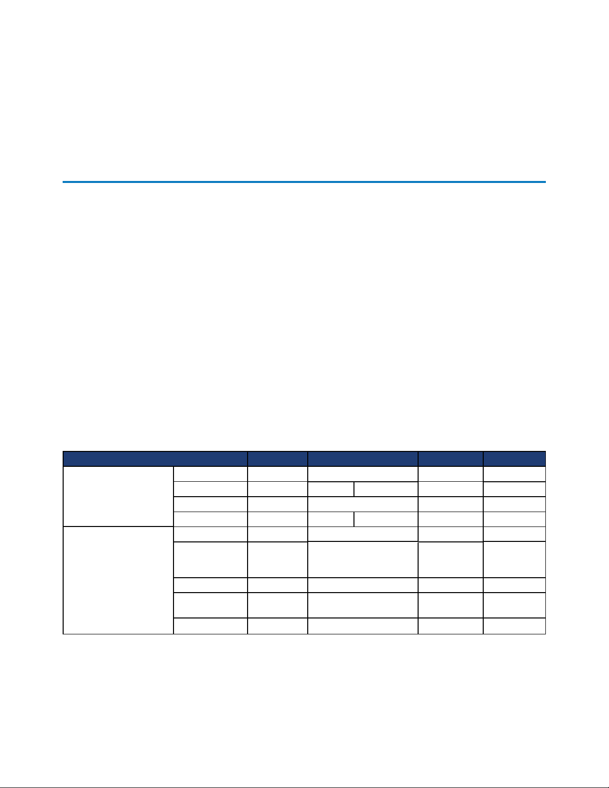
Table-1 describes the components of the 2U CN-Series system models.
Table-1 CN-Series system Model-specific Components
Component CN-2000 CN-2200 CN-3000 CN-5000
CPU
Front SSD Drives
Model Intel Xeon
CPU Count 1 1 2 2 2
Speed, GHz 2.4 or 2.6 2.4 or 2.6 2.5 2.7
Cores 6 or 8 8 8, 10, or 12 12 or 24 12 or 24
Quantity 4
Capacity 100 GB 400 GB
Interface SATA SATA SATA SATA
Dimension
RAID Type 5 1 5 5
2.5" (3.5"
carrier)
Intel Xeon
2
2.5" (3.5" carrier) 2.5" (3.5"
Intel Xeon
4
200 GB, 400
GB, or 800
GB
carrier)
Intel Xeon
6
400 GB or
800 GB
2.5"
8
OmniCube CN-Series Hardware Installation and Maintenance Guide 1 - Introduction to the CN-Series Hardware
6
5
4
11
2
3
4
8
7
Component CN-2000 CN-2200 CN-3000 CN-5000
Quantity 8 8 8 18
Capacity 1 TB 1 TB 3 TB 1.2 TB
Front HDD Drives
Rear HDDDrives
Memory 1333 MHz 128 GB
Power Supply
Network Interfaces
Deduplication and
Compression
Remote System
Management
Interface SATA SATA SAS SAS
RPM 7,200 7,200 7,200 10,000
Dimension
RAID Type RAID6 RAID6 RAID6 RAID60
Quantity 2 2 2 2
Capacity 300 GB 300 GB 300 GB 300 GB
Interface SATA SATA SAS SAS
Dimension 2.5" 2.5" 2.5" 2.5"
RPM 10,000 10,000 10,000 10,000
RAID Type 1 1 1 1
Hot swap,
integrated fans
Embedded
VM Network
[optional]
OmniCube Accelerator V2
IPMI processor and network port for remote, Web-based management.
3.5" (3.5"
carrier)
2 x 750W
2 x 10GbE or 2 x 1GbE
N/A 2 x 10GbE or 2 x 1GbE
3.5" (3.5" carrier) 3.5" (3.5"
carrier)
128 GB
min - 512
GB max
2 x
750W
256 GB min 512 GB max
2 x 750W (8
core) or 2 x
1100W (10 or
12 core)
128 GB min 512 GB max
2 x 750W (16
core) or 2 x
1100W (24
core)
2.5"
768 GB
2 x 1100W
CN-Series Enclosure Front Panel
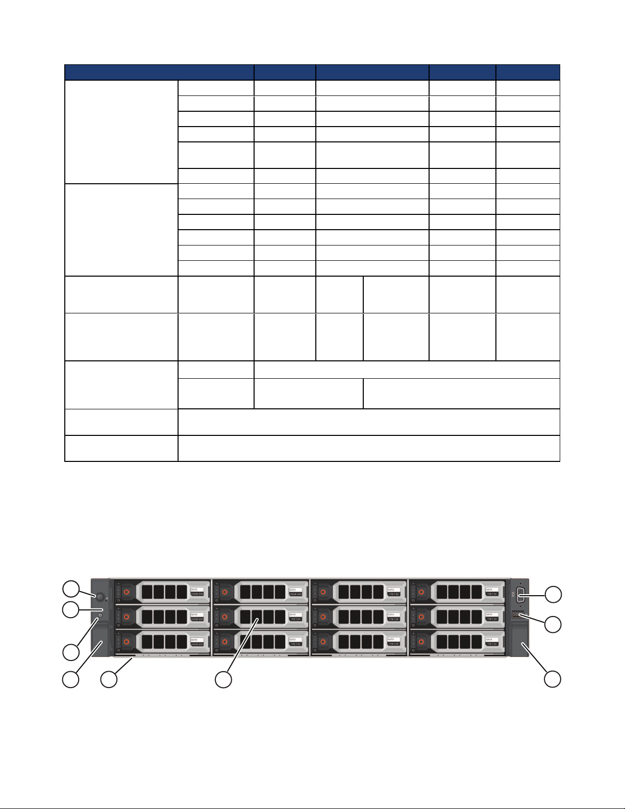
Figure-1 shows the front panel of a CN-2000 or CN-3000 with the bezel removed. Figure-2 shows the front
panel of a CN-2200 with the bezel removed. Table-2 describes the components of the front panel.
Figure-1: CN-2000 or CN-3000—Front View (Bezel Removed)
9
OmniCube CN-Series Hardware Installation and Maintenance Guide 1 - Introduction to the CN-Series Hardware
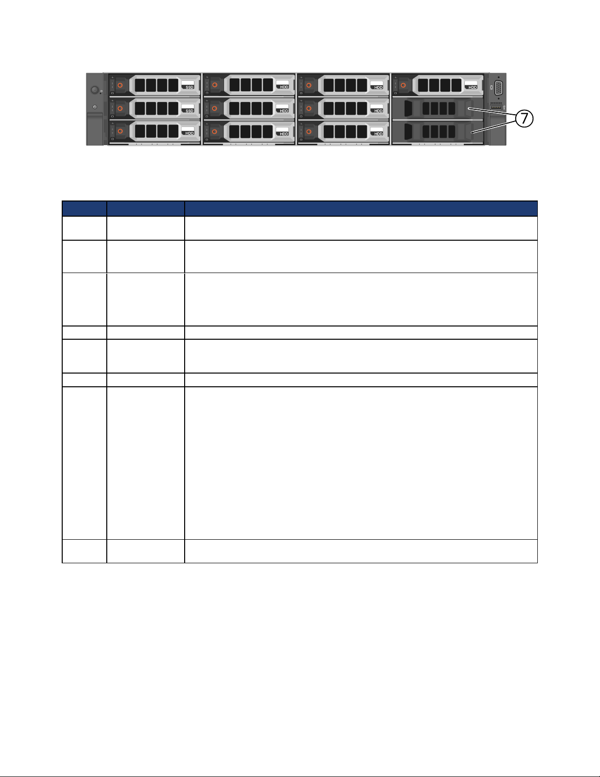
Figure-2: CN-2200—Front View (Bezel Removed)
Table-2 CN-2000, CN-2200, and CN-3000—Front Panel
Callout Component Description
1 Power button Controls power to the CN-Series system and indicates whether there is power present.
If the indicator is green, the CN-Series system is receiving power.
2 Diagnostic
indicators
3 System
identification
button
4 Retention latches Lock the CN-Series system enclosure in the rack, push to slide the enclosure out.
5 USB connector USB 2.0-compliant connector. Enables you to connect a USB device such as a
6 Video input Enables you to connect a monitor as part of a KVM for local administration.
7 Storage 3.5" disk drives with power (top) and activity (bottom) LED indicators. Labels
Show CN-Series system hardware error conditions.
See Diagnostic Indicators on page 38 for a description of each indicator.
Enables you to find a CN-Series system within a rack.
Push the system identification button on the front panel or the back panel. The
system identification buttons on the front panel and the back panel flash blue until
you push one of the buttons again.
keyboard as part of a KVM, for local administration. You can also insert a flash drive
when upgrading system software.
indicate the type (SAS/SATA) and capacity of each drive. For rotational drives, the
rotation speed (rpm) is indicated. The CN-2000 and CN-3000 have 12 drives. The
CN-2200 has 10 drives.
For the CN-2000 or CN-3000, the drives are numbered from 0 to 11, top to bottom,
and left to right. Drives 0 to 3 are SSDs and drives 4 to 11 are HDDs.
For the CN-2200, the drives are numbered from 0 to 9, top to bottom, and left to
right. Drives 0 and 1 are SSDs and drives 2 to 9 are HDDs. Drives 10 and 11 are
empty.
If you pull the CN-Series system enclosure from the rack, the drive numbering
scheme is described on a label attached to the top of the enclosure. See Identifying
Drive Problems on page 39 for drive LED details.
8 Service tab (pull-
out)
Provides identification information that might be required during a technical support
session. See Technical Support and Customer Service on page 7.
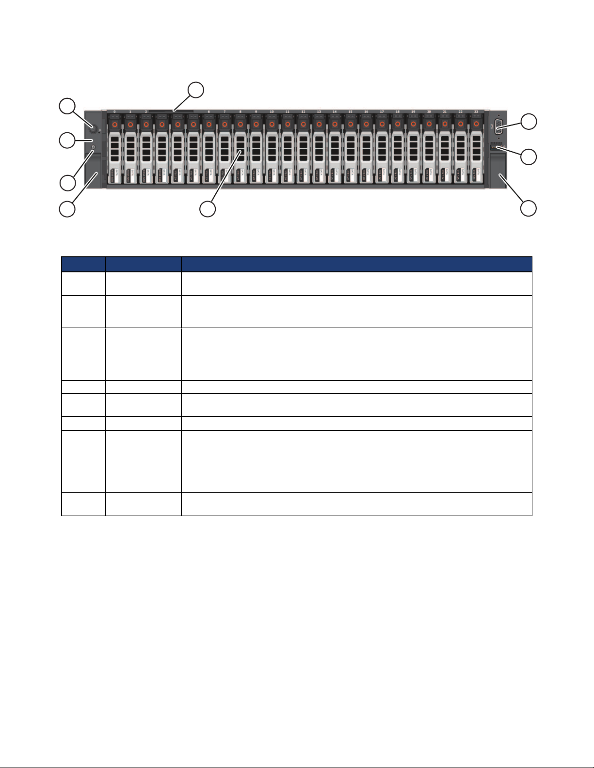
Figure-3 shows the front panel of a CN-5000 with the bezel removed. Table-3 describes the components of
the front panel.
10
OmniCube CN-Series Hardware Installation and Maintenance Guide 1 - Introduction to the CN-Series Hardware
6
5
4
11
2
3
4
8
7
Figure-3: CN-5000—Front View (Bezel Removed)
Table-3 CN-5000—Front Panel
Callout Component Description
1 Power button Controls power to the CN-Series system and indicates whether there is power to the
CN-Series system. If the indicator is green, the CN-Series system is receiving power.
2 Diagnostic
indicators
3 System
identification
button
4 Retention latches Lock the CN-Series system enclosure in the rack, push to slide the enclosure out.
5 USB connector USB 2.0-compliant connector. Enables you to connect a USB device such as a
6 Video Input Enables you to connect a monitor as part of a KVM, for local administration.
7 Storage 24 drives, size 2.5", with power (right) and activity (left) LED indicators.
Show CN-Series system hardware error conditions.
See Diagnostic Indicators on page 38 for a description of each indicator.
Finds a CN-Series system within a rack.
Push the system identification button on the front panel (or the back panel). The
system identification buttons on the front panel and the back panel flash blue until
you push one of the buttons again.
keyboard as part of a KVM for local administration.
Disks are numbered from 0 to 23, left to right. Disks 0 to 5 are SSDs. Disks 6 to 23
are HDDs. If you pull the CN-Series system enclosure from the rack, the disk
numbering scheme appears on a label attached to the top of the enclosure. See
Identifying Drive Problems on page 39 for LED details.
8 Service tab Provides identification information that might be required during a technical support
session. See Technical Support and Customer Service on page 7.
CN-Series Enclosure Back Panel
Figure-4 shows the back panel of all 2U CN-Series system. Table-4 describes the components of the back
panel.
11
OmniCube CN-Series Hardware Installation and Maintenance Guide 1 - Introduction to the CN-Series Hardware
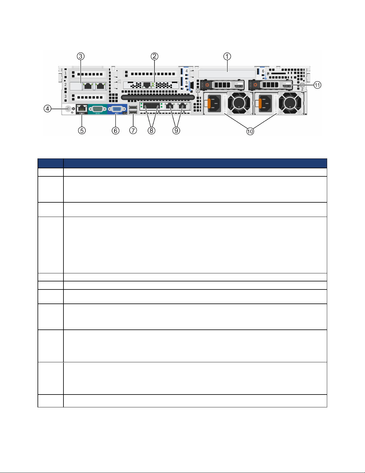
Figure-4: CN-Series 2U Enclosure Back Panel
Table-4 CN-Series 2U Enclosure Back Panel
Callout Description
1 Slot 6 - PERC H310 Disk controller.
2 OmniCube Accelerator™ (installed in slot 5 of riser 2) with two LEDs.
Both LEDs glow continuously to indicate normal operation. See Identifying OmniCube Accelerator
Problems on page 41 for LED details.
3 Optional 2x10GbE or 2x1GbE network card, used by guest VMs only and available only in the CN-
3000 and CN-5000.
4 System identification button and system identification connector.
The system identification button helps locate a CN-Series system within a rack. If you push the system
identification button on the back panel (or the front panel), the system identification buttons on the front
panel and the back panel flash blue. Push a system identification button a second time to stop it from
flashing.
The system identification connector, located to the right of the system identification button, connects the
optional system status indicator assembly through the optional cable management arm.
5 Dedicated IPMI port for remote Web-based management.
6 Video connector that enables you to connect a monitor or KVM.
7 Two USB connectors that are USB 2.0-compliant. Enables you to connect a monitor or KVM or insert a
flash drive for software upgrades.
8 Two 10GbE network interfaces, numbered 1 and 2. Each 10GbE interface has link (top) and activity
(bottom) round LEDs. These interfaces are dedicated to SimpliVity Federation networks.
See Identifying Network Interface Problems on page 44 for LED details.
9 Two 1GbE network interfaces, numbered 3 and 4, from left to right. Each 1GbE interface has link (top)
and activity (bottom) LEDs. Each 1GbE interface has link (left) and activity (right) square LEDs. These
interfaces are dedicated to SimpliVity Federation networks.
See Identifying Network Interface Problems on page 44 for LED details.
10 Two redundant, 750W or 1100W power supplies (with fans), numbered 1 and 2, from left to right. Each
power supply has a status indicator light in the handle. Disconnect the power cords before removing a
power supply. Wattage depends on the CPU requirements (number of cores).
See Identifying Power Supply Problems on page 45 for indicator light details.
11 Two hot-swappable 2.5" hard drives. Reserved for system use (not available for user data storage).
12
OmniCube CN-Series Hardware Installation and Maintenance Guide 1 - Introduction to the CN-Series Hardware
CN-Series Enclosure Interior
In rare cases, you might need access to the interior of a CN-Series system to perform maintenance tasks.
Warning: Many CN-Series system repairs may be done only by a service technician who is certified
by your support provider. You should perform troubleshooting and simple repairs only as
recommended in the product documentation, or as directed by the online or telephone service
and support team. Damage due to servicing that is not authorized by SimpliVity is not
covered by your warranty.
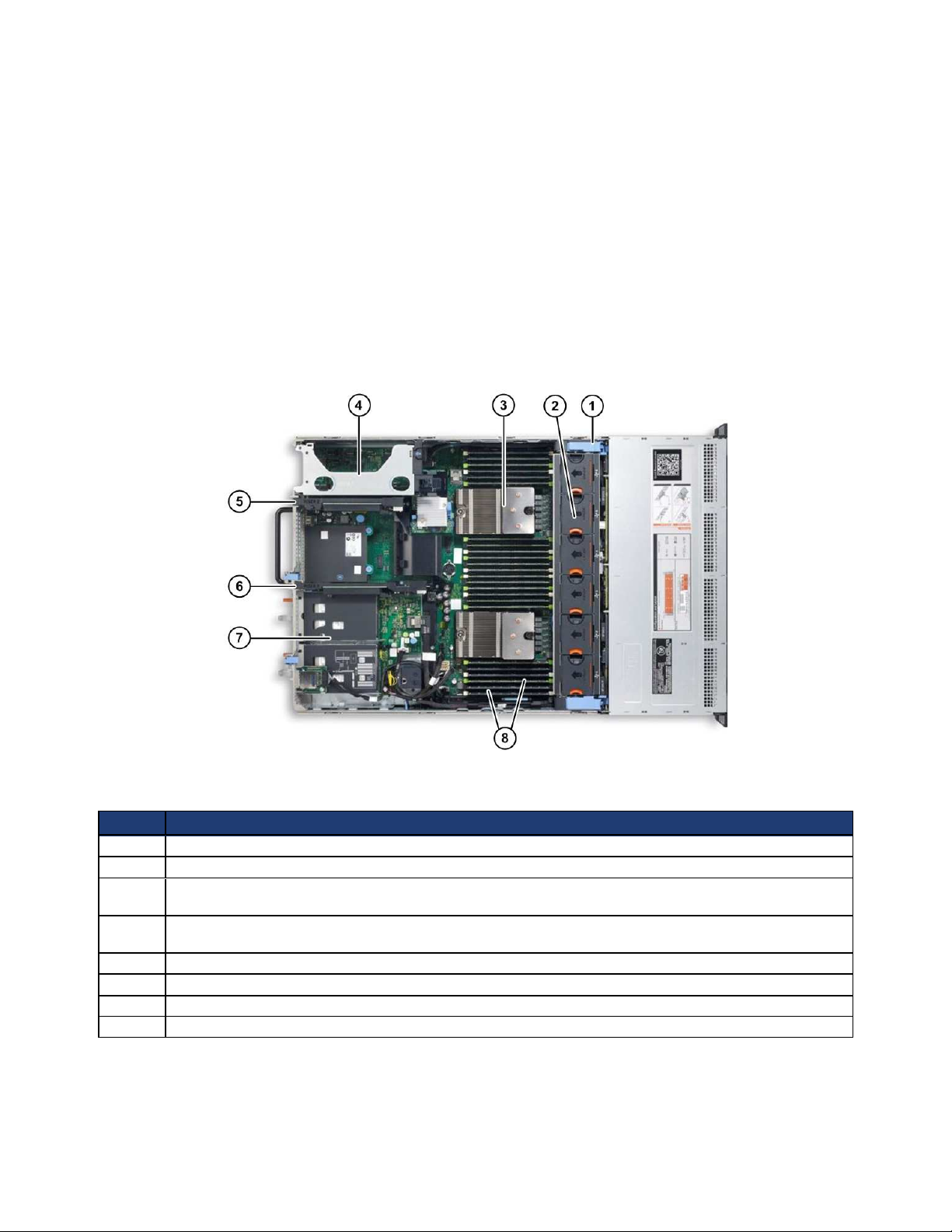
Figure-5 shows the interior of a CN-Series system. Table-5 describes the interior. To access the enclosure
interior, see Opening and Closing the Enclosure Cover on page 46.
Figure-5: CN-Series Enclosure Interior
Table-5 Enclosure Interior Description
Callout Description
1 Cooling-fan assembly. This is normally covered by a shroud that directs airflow over the CPU.
2 Individual cooling fans (6).
3 Heat sink for CPU. Depending on the model, there might be two processors. See CN-Series Hardware
Components on page 8.
4 Expansion card riser 1. This might contain an optional network card used only for guest VM network
traffic.
5 Expansion card riser 2, which contains the OmniCube Accelerator in slot 5 (bottom).
6 Expansion card riser 3, which contains the PERC H310 Disk controller.
7 Bays for the back panel hard drives. Both drives are reserved by SimpliVity for system use only.
8 Memory DIMMs (up to 24 DIMMs, depending on the CN-Series model).
13
OmniCube CN-Series Hardware Installation and Maintenance Guide 1 - Introduction to the CN-Series Hardware
CN-Series Environmental and Technical Specifications
The following sections describe the environmental and technical specifications for a CN-Series system. Use
this information to determine whether your intended installation location can provide the appropriate
environmental conditions and resources such as power and cooling.
Enclosure Size and Weights
Table-6 describes the dimensions of 2U CN-Series system models including:
• CN-2000
• CN-2200
• CN-3000
• CN-5000
Table-6 CN-Series 2U Enclosure Dimensions
Specification MM Inches
2U form factor 88.9 3.50
Maximum width (rack flange) 482.4 19.00
Enclosure width 444.0 17.50
Maximum height 87.3 3.43
Maximum depth (from rack flange) 28.50 723.0 28.5
Table-7 describes the weight of all CN-Series system models with all storage drives installed.
Table-7 Maximum Enclosure Weights
Specification Kg Lbs
CN-2000, CN-2200, and CN-3000 32.5 71.5
CN-5000 29.5 65.0
Power and Thermal
Table-8 describes the power and thermal specification for a CN-Series system with two redundant power
supplies.
Table-8 Power and Thermal Specifications
Specification CN-2000, CN-2200, and CN-3000 CN-5000
Current consumption 10A–5A 12A–6.5A
Supply voltage 100–240VAC (auto-ranging). Make sure
each power source has sufficient electrical
overload protection.
Frequency 50/60Hz 50/60Hz
Heat dissipation (BTU/hr 2843 / 2891 BTU/hr max 4100 BTU/hr max
100–240VAC (auto-ranging). Make sure
each power source has sufficient electrical
overload protection.
14
OmniCube CN-Series Hardware Installation and Maintenance Guide 1 - Introduction to the CN-Series Hardware
Specification CN-2000, CN-2200, and CN-3000 CN-5000
max.)
Maximum inrush current 55A 55A
Energy efficiency Energy Star, spec version 1.0 Energy Star, spec version 1.0
Power supply efficiency 90-96% efficient (load dependent) 89-92% efficient (load dependent)
Temperature and Humidity
Table-9 describes the temperature and humidity limits for a CN-Series system.
Table-9 Temperature and Humidity Specifications
Specification Maximum System Limits
Humidity and Temperature
(continuous operation)
Temperature (storage) -40°C to 65°C (-40°F to 149°F) with a maximum temperature gradation of 20°C per
10°C to 35°C (50°F to 95°F) at 10% to 80% relative humidity with 26°C (78.8°F)
maximum dew point (maximum wet bulb temperature). De-rate maximum allowable
dry bulb temperature at 1°C per 300m above 950m (1°F per 547 ft above 3117 ft).
hour.
Vibration and Shock Limits
Table-10 describes the vibration and shock maximum limit specifications for a CN-Series system.
Table-10 Vibration and Shock Limits
Specification Maximum System Limit
Vibration (operating) 0.26Grms at 5-350Hz in all orientations.
Vibration (storage) 1.87Grms at 10-500Hz for 15 minutes (all six sides tested).
Shock (operating) One shock pulse in the positive z axis (one pulse on each side of the system) of 31G +/–
5% for +/–10%; in the operational orientation.
Shock (storage) Half sine shock on all six sides of 71G +/– 5% with a pulse duration of 2ms +/–10%;
square wave shock on all six sides of 27G with velocity change at 235 in/sec or greater.
Altitude and Airborne Contaminants
Table-11 describes the maximum altitude and airborne contaminants specifications for all CN-Series system
models.
Table-11 Altitude and Airborne Contaminant Specifications
Specification Maximum System Limit
Altitude (operating) -15.2m to 3048m (–50 ft to 10,000 ft)
Altitude (storage) -15.2m to 12,000m (–50 ft to 39,370 ft)
Contaminant level (operating) Class G1 or lower as defined by ISA-S71.04-1985
15

OmniCube CN-Series Hardware Installation and Maintenance Guide 1 - Introduction to the CN-Series Hardware
Agency Compliance
Table-12 lists agency compliance for all CN-Series systems.
Table-12 Agency Standards Compliance
Standard
FCC47 CFR Part 15 Subpart B: 2012
EN 55022:2010 COR 2011
CISPR 22:2008
EN 55024:2010
CISPR 24:2010
COR 2011
VCCIV3:2009
ANSI/UL 60950-1, 2nd Edition (2007)
CSA C22.2 No. 60950-1 2nd Edition (2007)
IEC 60950-1:2005 (2nd Edition); Am 1:2009
RoHS EU Directive 2002/95/EC
16

17

2 - Installing the CN-Series System
This section describes how to install a CN-Series system for a minimum Federation that contains two
OmniCube systems. As your storage and performance needs increase, you can add more OmniCube systems
to a Federation.
See the OmniCube Release Notes for configuration constraints that apply in this release.
General Guidelines for Installing Hardware in a Rack
SimpliVity recommends that you install the hardware in a rack according to the following guidelines:
• Follow all safety guidelines stated in the rack's documentation, particularly when installing components
into the locations at the top of the rack.
• Make sure the rack meets the requirements in Rack Requirements on page 22.
• Install systems in the same rack when possible.
• Install systems in a rack starting from the bottom of the rack.
• Always install a CN-Series system in a horizontal position, or you void your warranty and support
contract.
Tasks for Installing the Hardware
After you install the CN-Series system in a rack and connect power and network cables, you can create a
datacenter within vCenter Server and deploy each CN-Series system as an OmniCube in a Federation.
Complete these tasks to install the hardware for a Federation containing two OmniCube systems:
• Task 1—Perform the Pre-Installation Tasks on page 19
• Task 2—Install the CN-Series Enclosure in a Rack on page 24
• Task 3—Connect the Power Cables on page 25
• Task 4—Connect the Network Cables on page 26
• Task 5—Configure IPMI for Remote Management on page 30
• Task 6—Configuring the ESXi Host on page 33
18
 Loading...