

Page 1
Power. On Your Terms.
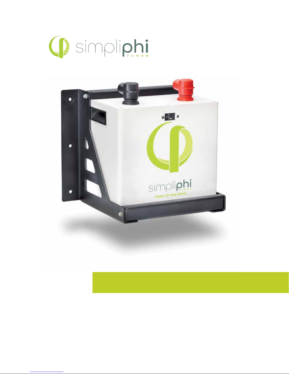
PHI2.6™ SMARTTECH BATTERY
Optimized Energy Storage & Management for Residential & Commercial Applications Utilizing
Ecient, Safe, Non-Toxic, Energy Dense Lithium Ferrous Phosphate (LFP) Chemistry.
INSTALLATION MANUAL
© SIMPLIPHI POWER, INC. REV081716
Page 2

SimpliPhi Your
Power Security
and Independence
and gain control of your own power.
SimpliPhi helps you manage your power as a personal resource.
Anytime. Anywhere. SimpliPhi energy storage optimizes integration
of renewable power with the grid and protects your home and
mission-critical business functions from power outages and
intermittency. SimpliPhi storage technology eliminates operating
temperature constraints, toxic coolants and the risk of thermal
runaway and fire.
SimpliPhi’s clean storage technology utilizes the industry’s most
environmentally benign chemistry combined with proprietary
architecture and power electronics (BMS) that eliminate the need
for cooling or ventilation to create products that provide energy
security and resiliency—all with a 98% eciency rate.
SimpliPhi Power oers proprietary, commercially available energy
storage and management systems that are safe, non-toxic,
reliable, durable, ecient, highly scalable, and economical over
the lifetime of the battery.
SimpliPhi Power, Inc. | 420 Bryant Circle | Ojai, CA 93023, USA | +1 (805) 640-6700 | [email protected] | SimpliPhiPower.com
| 2 |
Page 3

Table of Contents
Page 4
PHI2.6™ Smart-Tech Battery Safety Protocol
Safety & Protective Features
• 80Amp Breaker
• BMS
PHI2.6™ Smart-Tech Battery Technical Overview
PHI2.6™ Smart-Tech Battery Construction
PHI2.6™ Smart-Tech Battery Performance and Sizing Calculations
Page 7
Installation Procedure and Diagrams
System Sizing for Your Installation
System Configuration - Basic Concepts
Increasing Storage Capacity
Sample Installation Requirement
Mounting Hardware & Weight
Page 13
Key Points
Page 14
Connecting PHI2.6™ Smart-Tech Batteries
Connection Terminals
Cable Leads
Installation Connection
Guide for Operating Perameters
Page 17
Charge Controller Integration
24 Volt System
48 Volt System
Page 19
PHI Lithium Ferrous Phosphate (LFP) BMS Features and Specifications
Page 20
PHI2.6™ Smart-Tech Battery Units
Safety Attributes and Certifications
Green Characteristics, Environmental and Ecological Considerations
Page 23
Appendix
Materials Safety Data Sheet
SimpliPhi Power, Inc. | 420 Bryant Circle | Ojai, CA 93023, USA | +1 (805) 640-6700 | [email protected] | SimpliPhiPower.com
| 3 |
Page 4

The SimpliPhi Power PHI2.6™ Technical Overview:
PHI2.6™ Smart-Tech Battery Safety Protocol and
Protective Features
Safety Protocol:
IMPORTANT NOTE: Circuit Breakers, Disconnects and Fuses should be employed throughout
several points of a power storage and generation installation to eectively isolate and protect all
components of the system to safeguard against faults, short circuits, polarity reversals or a failure of
any component in the overall system. Fuses, breakers, wiring ratings and values should be determined
by established standards and evaluated by certified electricians, licensed installers, and regional code
authorities. Although each PHI2.6™ Smart-Tech Battery contains both an 80 Amp circuit breaker and
an internal BMS with circuitry that protects the Lithium Ferrous Phosphate cells from overcharge, overdischarge and excessive load amperage, the PHI2.6™ Smart-Tech Batteries must always be installed with a
charge controller and the appropriate settings to protect the PHI2.6™ from open PV voltage and other high
voltage charging sources. The PHI2.6™ Smart-Tech Battery Management System (BMS) and internal circuit
breaker alone will not protect the PHI batteries from these extreme electrical phenomena. Failure
to adhere to installation protocol will void the Warranty.
CAUTION: Verify polarity at all connections with a standard volt meter before 1) energizing the
system and 2) turning the PHI2.6™ 80 Amp breaker “ON/OFF” switch to the “ON” position. Reverse polarity
at the battery terminals will void the Warranty and destroy the batteries.
PHI2.6™ Smart-Tech Batteries pose some risk of shock or sparking during the installation and initial wiring
and connection process. This is consistent with all other battery based storage formats. Be sure to turn
the built-in 80 Amp breaker to the “OFF” position to minimalize the risk of shock or sparks during the
installation and commissioning of the system. Use of insulated gloves, clothing and footwear is always
recommended when working in close proximity to electrical devices. Cover, restrain or remove jewelry
or conductive objects (metal bracelets, rings, belt buckles, metal snaps, zippers, etc.) when working with
any electrical or mechanical device. Cover or restrain long hair and loose clothing when working with any
electrical or mechanical device.
PHI2.6™ Smart-Tech Batteries do not vent any harmful gasses, and do not require special ventilation
or cooling.
PHI2.6™ Smart-Tech Batteries are not capable of thermal runaway. If the cells are severely damaged due to
physical abuse incurred outside of warranted specifications, which can cause electrolyte leakage and other
failures, as with any battery, the electrolyte can be ignited by an open flame. However, unlike other lithium
ion batteries (LCO) there are no hazardous or toxic materials in the electrolyte or the material components
of PHI2.6™ Smart-Tech Batteries. See MSDS for chemical analyses (Page 23).
SimpliPhi Power, Inc. | 420 Bryant Circle | Ojai, CA 93023, USA | +1 (805) 640-6700 | [email protected] | SimpliPhiPower.com
| 4 |
Page 5
CAUTION: Charging LFP batteries at temperatures below freezing.
Do not attempt to charge the battery below 32 F (0 degrees C). Although cold temperatures do not harm
PHI batteries, attempts to charge at subfreezing temperatures can adversely aect SOH and cycle life, and
will void the Warranty. If the battery must be charged below 32 F (0 degrees C), the rate of charge must be
at no more than 5% of the battery’s rated capacity (C/20).
Only use a SimpliPhi approved LFP charger if ancillary charging is required before installation, testing or troubleshooting. Failure to use a SimpliPhi approved LFP charger will damage the battery and void the warranty.
SimpliPhi Power PHI2.6™ Smart-Tech Protective Features:
PHI2.6™ Smart-Tech Batteries are manufactured utilizing Lithium Ferrous Phosphate (LFP) cells, which are
produced under exclusive patented licensed technologies, as well as proprietary materials, architecture,
assembly methods and battery management system (BMS). This assures the highest grade and quality,
longest cycle-life, greatest eciency and freedom from material impurities, toxicity and hazardous risk.
Each PHI2.6™ Smart-Tech Battery contains circuitry that protects the Lithium Ferrous Phosphate cells
from overcharge, over-discharge and excessive load amperage. If the values specified are exceeded, the
protective circuitry will shut down the flow of electricity to/from the PHI2.6™ Smart-Tech Batteries. In some
cases this will result in the need to re-initialize an inverter charger. Often, inverter system settings will be
saved within the inverter memory storage and will not need to be reset. This is not an absolute standard
but is common amongst most inverter chargers and should be anticipated if the PHI2.6™ Smart-Tech
Batteries go into a state of self-protection and shut down the flow of electricity.
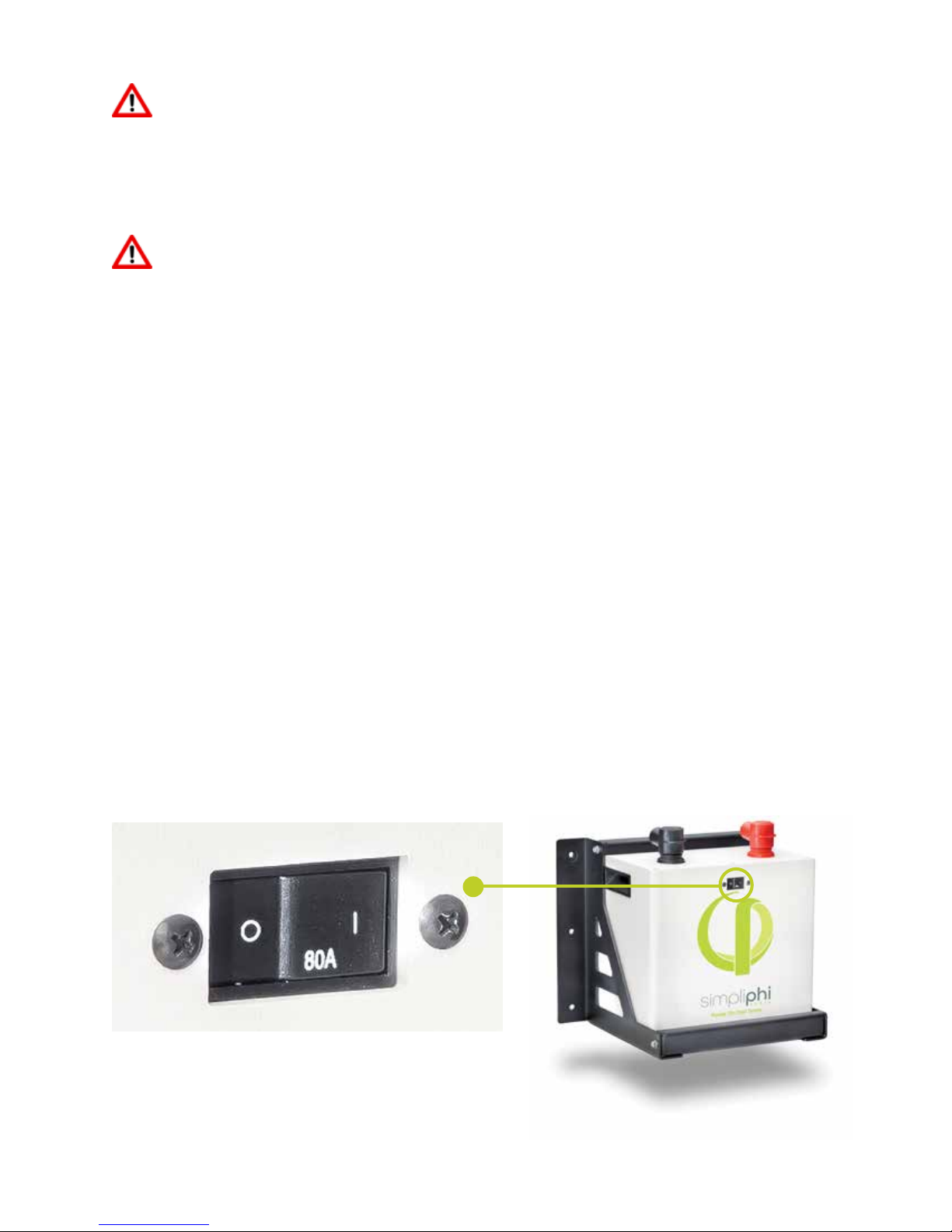
In addition, the PHI2.6™ Smart-Tech Battery is equipped with a built in 80 Amp breaker that eectively works
as an “ON/OFF” switch to be used during shipping and installation. The breaker works in conjunction with
the built in battery management system (BMS) and creates additional safety, eciency
and functionality to the overall power storage system.
Figure 1.0 Photo depicts “On Position”
SimpliPhi Power, Inc. | 420 Bryant Circle | Ojai, CA 93023, USA | +1 (805) 640-6700 | [email protected] | SimpliPhiPower.com
| 5 |
Page 6
SimpliPhi Power PHI2.6™ Smart-Tech Battery Performance Parameters
and Sizing Calculations:
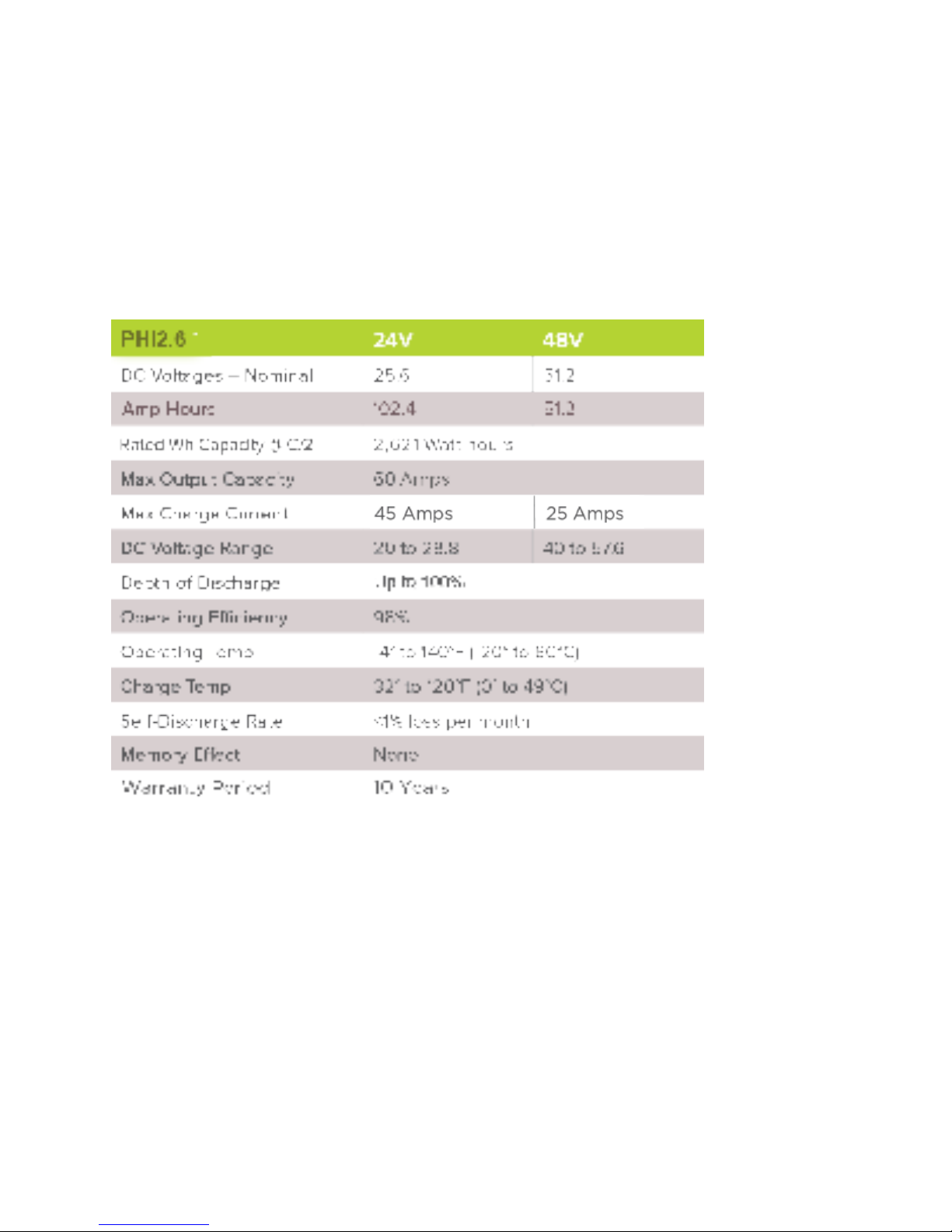
PHI2.6™ Smart-Tech Batteries perform at full rated capacity in most operating environments. No increase
in sizing, no special compensations, no burying procedure or insulation needs to be considered when
determining the size of the energy storage and management system under the following circumstances
and conditions.
See specific inverter manufacturer program settings for optimizing system integration
Note: There is less than 1% loss of energy during charging.
PHI2.6™ Smart-Tech Batteries do not need to be de-rated unless running continuously at more than 90%
capacity, at temperatures below 0 degrees Celsius, or above 60 degrees Celsius. To achieve higher cycles
of 10,000+, please refer to operating temperatures and inverter settings on page 16 of the manual. Further
details are available on request from SimpliPhi Power.
SimpliPhi Power, Inc. | 420 Bryant Circle | Ojai, CA 93023, USA | +1 (805) 640-6700 | [email protected] | SimpliPhiPower.com
| 6 |
Page 7

Installation Procedure and Diagrams
System Sizing for Your Installation
The number of PHI2.6™ Smart-Tech Batteries should be specified in terms of total storage capacity before
the initial installation based on the goals and objectives of the project. All PHI2.6™ Smart-Tech Batteries
are balanced during final production and testing stages. Following proper wiring guidelines ensures that a
system will not require any manual balancing processes.
DO NOT COMBINE PHI2.6™ SMART-TECH BATTERIES WITH OTHER
BRANDS OR CHEMISTRIES
DO NOT MIX PHI SMART-TECH BATTERIES FROM DIFFERENT
INSTALLATIONS, CLIENTS, OR JOB SITES
System Configuration - Basic Concepts
Safe and reliable installation requires trained and certified technicians. The following discussion of PHI SmartTech Battery configurations is a basic primer. Due to the variety of systems and components in the field, all
possible scenarios are not covered. This is not the purpose of this section of the manual. Refer to professional
installers regarding your system and its components and specifications. We encourage you or your installer to
contact us with any specific questions for technical support. We are committed to working with you and your
installation team to achieve a safe, reliable storage system that will provide years of maintenance free service.
SimpliPhi Power, Inc. | 420 Bryant Circle | Ojai, CA 93023, USA | +1 (805) 640-6700 | [email protected] | SimpliPhiPower.com
| 7 |
Page 8
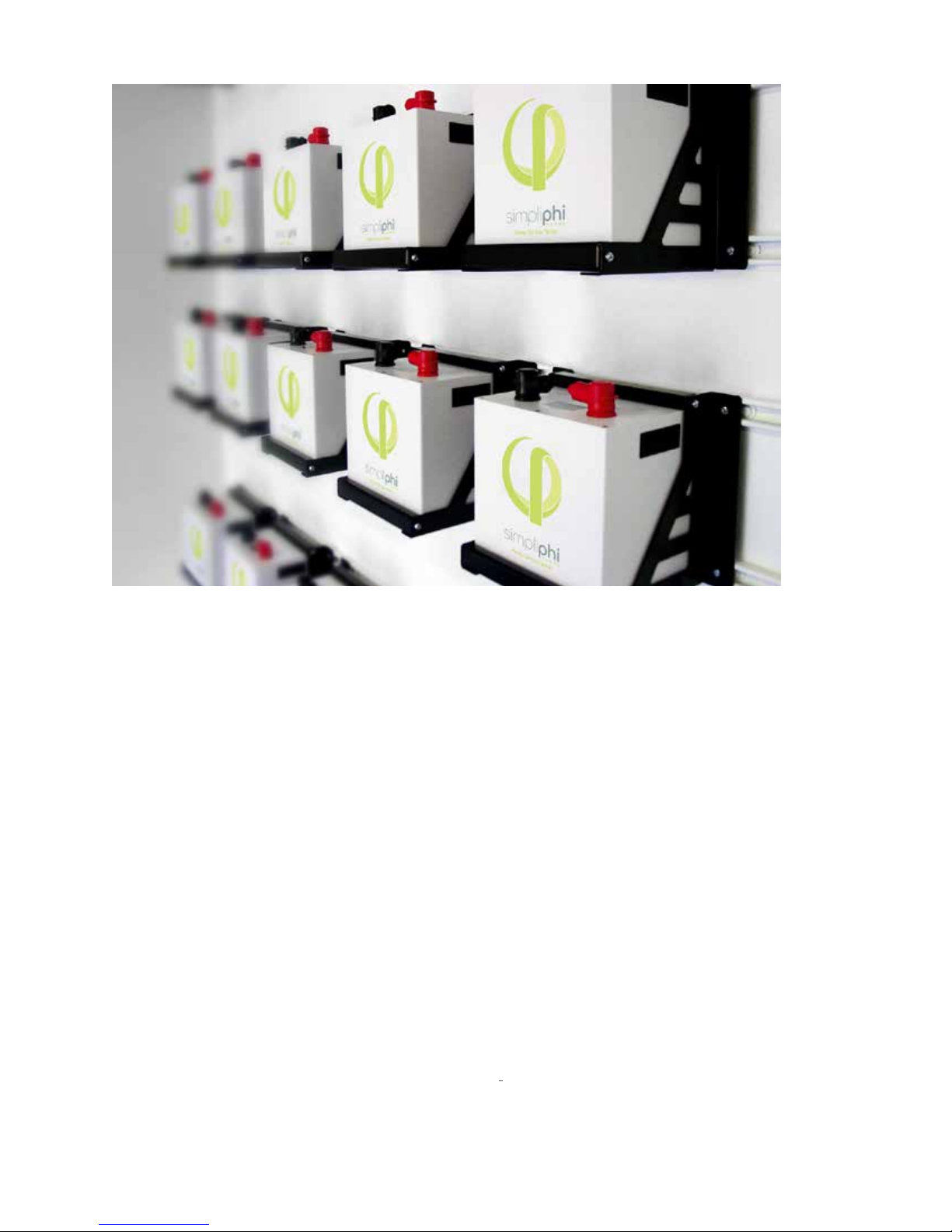
Figure 2.0 - PHI2.6™ 48 Volt, 2621 watt-hour (2.6kWh) Smart-Tech Batteries: Residential Installation
PHI SMART-TECH BATTERIES ARE DESIGNED FOR PARALLEL OPERATION ONLY - DO NOT ARRANGE
IN SERIES FOR INCREASED VOLTAGE
System Wiring Basics
Refer to published electrical wiring specifications and ratings. All wire should be an appropriate gauge and
construction to handle the loads that will be placed upon it. Heavy gauge, high strand copper wire is the
industry standard due to its stability, eciency and overall quality. A qualified installer should understand
this and must adhere to the industry standard and published electrical guidelines.
For All Installations
• Maintain identical wire lengths from each PHI2.6™ Smart-Tech Battery terminal to the common bus.
• Use identical wire construction from each PHI2.6™ Smart-Tech Battery terminal to the common bus.
All PHI2.6™ Smart-Tech Batteries are outfitted with an 80A hydraulic/magnetic circuit breaker which will
show a white base when tripped. This breaker increases safety during installations and allows the battery
to eectively be turned “o” or “on.”
All PHI2.6™ Smart-Tech Batteries are designed to serve at a fixed voltage range in parallel arrangements for
maximum available amperage and storage capacity. PHI2.6™ Smart-Tech Batteries are not
designed to be arranged in series for increased voltage. Series arrangements can result in damage to
the Smart-Tech Battery’s protective circuitry and will void the Warranty.
SimpliPhi Power, Inc. | 420 Bryant Circle | Ojai, CA 93023, USA | +1 (805) 640-6700 | [email protected] | SimpliPhiPower.com
| 8 |
Page 9
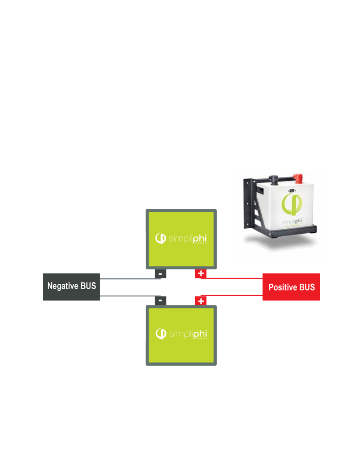
Simple Parallel Arrangements
Storage Capacity and total available Amperage is increased by Parallel arrangements. The following
illustration shows two PHI2.6™ Smart-Tech Batteries in Parallel. For example, assume that these are 24V
Smart-Tech Batteries.
Note the overall Voltage range is not changed. The arrangement remains at 24 Volts, the available AH
capacity, or ability to provide 24 Volt power over time, has been doubled. The available amperage from
the system has been doubled. The same configuration should be applied to other parallel arrangements,
whether they are 24V or 48V. See Figure 1.2.
Simple Parallel Arrangements:
Storage Capacity and total available Amperage is increased by Parallel arrangements. The following
illustration shows two PHI2.6™ Smart-Tech Batteries in Parallel.
PHI SMART-TECH BATTERIES ARE DESIGNED FOR PARALLEL OPERATION ONLY - DO NOT ARRANGE
IN SERIES FOR INCREASED VOLTAGE
WIRING IN SERIES WILL VOID WARRANTY
Figure 1.2 - A single PHI2.6™ Smart-Tech Battery
Figure 1.3
Figure 1.3 represents two PHI2.6™ Smart-Tech Batteries in Parallel. Wire lengths from PHI Smart-Tech
Batteries should be identical in length and gauge in order to balance the load across both (all) PHI SmartTech Batteries in the installation. Identical wiring length is a critical feature of parallel power storage
systems that must be adhered to throughout all parallel wiring instructions.
SimpliPhi Power, Inc. | 420 Bryant Circle | Ojai, CA 93023, USA | +1 (805) 640-6700 | [email protected] | SimpliPhiPower.com
| 9 |
Page 10
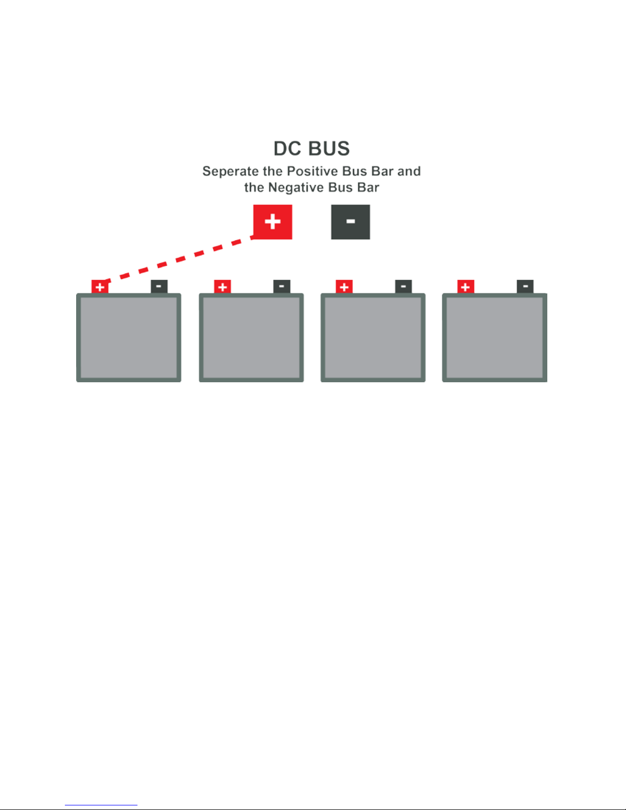
Increasing Capacity with Parallel PHI Smart-Tech Battery Configurations
Special attention should be paid for parallel installations. Correct wiring is essential to insure optimum
performance and system longevity. All wire “runs” should utilize identical wiring gauge and identical wire
lengths between PHI2.6™ Smart-Tech Batteries and the common negative or positive “Bus” or Load.
Use identical length and gauge wire to balance the load across the batteries.
Helpful Tips:
• Determine the cable length for the battery terminal farthest from the bus.
• Make all Battery cables a matching length.
• Additional cabling or slack that remains with the shorter distance runs can be coiled
and secured with Zip Ties.
Figure 1.4
Figure 1.4 depicts one of four PHI2.6TM Smart-Tech Batteries that will have been wired in Parallel. The wiring
arrangement will be repeated to connect all four Smart-Tech Batteries in parallel. The completion of this
configuration will require 8 identical lengths of appropriately heavy gauge copper wire.
Alternate wiring schemes are also eective. The “Cross Diagonal” method is perhaps less common but
has been evaluated in outside facilities and found to be very eective. The Cross diagonal method can
minimize copper wire runs to a degree and can also serve as a tool in complex wiring schemes where
space is at a minimum or system layouts are complex or irregular. For more information on cross diagonal
wiring methods, and the benefit of correct wiring configurations, refer to:
http://www.smartgauge.co.uk/batt_con.html
SimpliPhi Power, Inc. | 420 Bryant Circle | Ojai, CA 93023, USA | +1 (805) 640-6700 | [email protected] | SimpliPhiPower.com
| 10 |
Page 11

Mounting Hardware
The SimpliPhi Power Mounting Brackets (sold separately) are designed to secure one PHI2.6™ Smart-Tech
Battery to a load bearing surface. SimpliPhi Power Smart-Tech Batteries can be mounted in practically
any orientation (Terminals Up, Down, On Side). The brackets can be mounted directly to a wall or
can be arranged on strut channels for ease of positioning. A qualified installer should be familiar with
accomplishing this with the appropriate load bearing requirements.
Mounting Bracket Hardware is also included: 1/4-20 x 5/8” Hex Washer Head Machine Screw - Slotted.
18-8 Stainless Steel
For ease of measuring, arranging and mounting your PHI Smart-Tech Battery array, a drawing of the PHI2.6™
Mounting Brackets with dimensions is provided (page 12):
During mechanical testing, individual PHI2.6™ Mounting Brackets were exposed to 200 pounds each of
downward pressure along the bracket’s outer edge. During this test, a deflection of approximately 30
thousandths of an inch was measured. Combined bracket sets can easily bear weights in excess of 400
pounds. Bracket sets are designed to hold one PHI2.6™ Module, with a weight of 57.5 pounds.
PHI2.6™ Smart-Tech Battery Weight
PHI2.6™ Smart-Tech Batteries weigh 57.5 pounds. The Wall Mount Bracket Assemblies weigh 8 Pounds.
The SimpliPhi Power Mounting Brackets should be mounted into load bearing beams, studs or solid posts.
Check with your installer to select an appropriate wall space or surface.
PHI2.6™ Smart-Tech Battery Wall Mount + Bracket Dimensions
PHI2.6™ Battery
Width: 11.25’’
Height: 13.5’’ (including terminal height)
Depth: 9.5”
Weight: 57.5 Pounds
PHI2.6™ Battery with Bracket
Width: 15.5”
Height: 13.5” (including terminal height)
Depth: 10.44”
Weight: 65.5 pounds
SimpliPhi Power, Inc. | 420 Bryant Circle | Ojai, CA 93023, USA | +1 (805) 640-6700 | [email protected] | SimpliPhiPower.com
| 11 |
Page 12
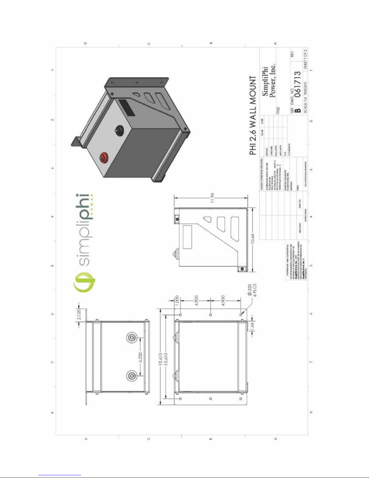
(BMS)
with Integrated
48V Battery Modules
PHI2.6™ KWH 24V and
Battery Management
Figure 1.5
SimpliPhi Power, Inc. | 420 Bryant Circle | Ojai, CA 93023, USA | +1 (805) 640-6700 | [email protected] | SimpliPhiPower.com
| 12 |
Page 13

KEY POINTS
1. Each PHI2.6™ Smart-Tech Battery contains circuitry that protects the Lithium Ferrous Phosphate
cells from overcharge, over-discharge, excessive charge and load amperage. If the values
specified are exceeded, the Smart-Tech Batteries will enter a protective shut down state. In some
cases this will result in the need to re-initialize an inverter charger or other pieces of equipment in
the installation. Often, inverter system settings will be saved within the inverter memory storage
and will not need to be reset. This is not an absolute standard but is common among most inverter
chargers. Check your inverter manufacturer specifications.
2. If PHI2.6™ Smart-Tech Batteries enter a self protective mode, negligible voltage readings will be
present until the units reset. In some instances, after a prolonged shut down, a charge might need
to be manually applied to the energy storage bank. Should this occur, please contact SimpliPhi
Power for technical support. The PHI Smart-Tech batteries are designed to remain robust and safe
under most circumstances.
3. Although each PHI2.6™ Smart-Tech Battery contains circuitry that protects the Lithium Ferrous
Phosphate cells from overcharge, over-discharge and excessive load amperage, the PHI2.6™
Smart-Tech Batteries must always be installed with a charge controller and the appropriate settings
to protect the PHI2.6™ from open PV and other high voltage sources. The PHI2.6™ Smart-Tech
Battery alone will not protect the batteries from these extreme electrical phenomena.
4. GRID TIED SYSTEMS: Once the PHI2.6™ Smart-Tech Batteries have been installed, turn on the
entire system to test, but once testing has been completed please disconnect the PHI2.6™
Smart-Tech Battery Bank from the load center until your local Utility Inspector is ready to
turn on the entire system. The charge controllers and inverter monitoring systems can drain the
PHI2.6™ Smart-Tech Batteries over an extended period of time when the entire system is not fully
operational due to the electrical draw of the system components.
5. OFF GRID SYSTEMS: Do not connect the PHI2.6™ Smart-Tech Batteries until the entire system is
ready to turn on and is fully operational. Install with the 80 Amp breaker in the “OFF” position.
6. See Charge Controller Settings in the Appendix of this manual. PHI2.6™ Smart-Tech Batteries are
compatible with almost all Inverter Chargers and Charge Controllers. Please contact SimpliPhi
Power for recommended settings for any device not expressly covered in this manual.
7. Only use a SimpliPhi approved LFP charger if ancillary charging is required before installation, testing
or troubleshooting. Failure to use a SimpliPhi approved LFP charger will damage the battery and void
the warranty.
8. CAUTION: Charging PHI LFP batteries at temperatures below freezing.
Do not attempt to charge the battery below 32 F (0 degrees C). Attempts to charge at
subfreezing temperatures can adversely aect SOH and cycle life, and will void the warranty.
If the battery must be charged at temperatures below freezing the rate of charge must be at no
more than 5% of the battery’s rated capacity (C/20).
SimpliPhi Power, Inc. | 420 Bryant Circle | Ojai, CA 93023, USA | +1 (805) 640-6700 | [email protected] | SimpliPhiPower.com
| 13 |
Page 14
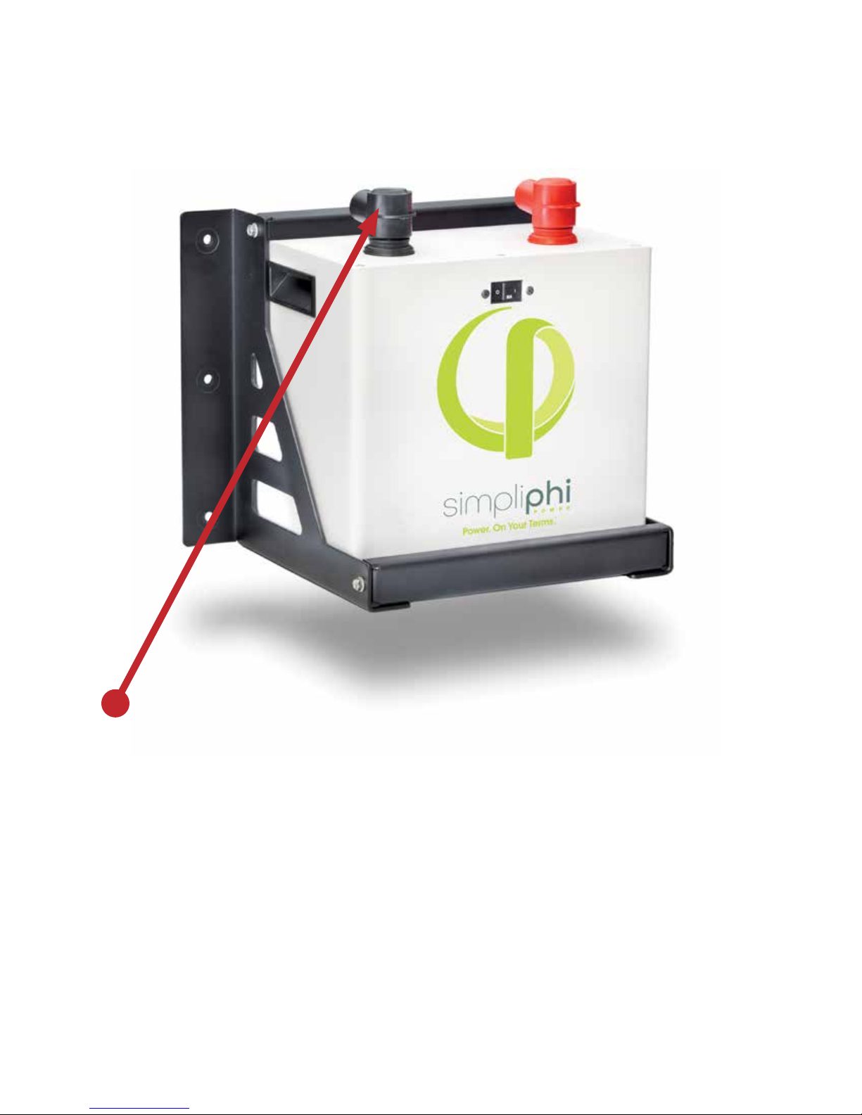
Connecting SimpliPhi Power PHI2.6™ Smart-Tech
Batteries: Terminal Specs and Hardware
CAUTION: DO NOT ATTEMPT TO LOOSEN THE LARGE BRASS NUT AT THE BASE OF THE TERMINALS.
PHI2.6™ Smart-Tech Battery Connection Terminals
The PHI2.6™ Smart-Tech Batteries are equipped with two 3/8’’ threaded studs with a lock washer and nut.
The right hand stud resides in a red colored high temperature molded insert. This connection is for the
positive lead. The left hand stud resides in a black colored high temperature insert. This connection is for
the negative lead. Do not reverse polarity. It will void the warranty. Use a volt meter to check polarity
before connecting terminals.
Water Resistant Cable Boots are also included and will be in place when your units arrive. The boots are to
be placed over the cable terminations and will stretch to form a water resistant seal around the base of the
molded inserts and terminal connections.
SimpliPhi Power, Inc. | 420 Bryant Circle | Ojai, CA 93023, USA | +1 (805) 640-6700 | [email protected] | SimpliPhiPower.com
| 14 |
Page 15

Connecting Cable Leads to the PHI2.6™ Smart-Tech
Batteries:
NOTICE: SPARK MAY BE PRESENT WHEN CONNECTING WIRES TO PHI2.6™ TERMINALS
A brief small spark is often present when connecting the second of two leads to a battery. Example: If the
Positive has been connected, a small spark will likely be present when connecting the Negative lead. This
is a normal occurrence. Complete all connections in a clean, ventilated, well lit area. To avoid any spark or
electrical event when connecting the terminal leads on the PHI2.6™ Smart-Tech Battery, turn the 80 Amp
breaker “ON/OFF” switch to “OFF” position.
Power Cabling for the PHI2.6™ Smart-Tech Battery is not included. Your qualified installer or application
specifications will determine the wire gauge for your system.
Considerations for Power Cable Terminations
- PHI2.6™ Smart-Tech Battery Mounting Stud Size: 3/8’’
- Power Cable Wire Gauge: Generally anywhere from 6 AWG to 2/0 AWG or larger.
High amperage rated ring terminals can be found for these and other common dimensions. Your installer
can source these or we can provide them based on the specifications you provide.
Protection from the Environment
Anticorrosive compounds or epoxies are occasionally used in harsh or marine climate installations. Please
contact your Electrician or Qualified Installer to determine if this is advisable, and if so, what solution best
suits your application.
Final Connection of the Installation
Final installation and operation guidelines will be dictated by your Electrician and Installer based on the
overall properties of and procedures for the equipment in your installation and any code requirements
that apply to your region. SimpliPhi Power, Inc. technicians and sales sta are available to provide any
additional information on the PHI2.6™ Smart-Tech Battery as needed. Please contact SimpliPhi Power for
any technical support at your convenience. SimpliPhi Power, Inc. is committed to providing safe, reliable
energy storage and management that is maintenance free, non-toxic and long-lasting. This commitment
extends to our customers, valued installers, partners, and to the community at large. Please be aware
of the potential electrical hazards before interacting with any and all electrical or mechanical devices.
Please take all necessary precautions in your projects and installations. Please refer to page 4 for safety
guidelines.
PHI Smart-Tech Batteries feature a Low Battery Voltage Cut O (LBCO). This is a self protection mechanism
that prevents over discharge. The LBCO will cause the battery to turn o once batteries approach Zero
Capacity or 100+ percent depth of discharge.
SimpliPhi Power, Inc. | 420 Bryant Circle | Ojai, CA 93023, USA | +1 (805) 640-6700 | [email protected] | SimpliPhiPower.com
| 15 |
Page 16

Most, if not all, inverters have related features. These features are often referred to as “Load Disconnect”,
“Load Shedding” or similar. These features are there to protect the battery bank from excessive discharge.
In instances of low battery voltage, when there is no incoming energy to recharge the battery bank, the
inverter will disconnect the load and remain in standby until the battery bank is recharged.
For O Grid installations, where charge energy is only provided by PV arrays, Inverter “Load Disconnects”
are generally set at a value that will allow a system to remain online and in standby for at least 24 hours
(10% at top of charge and 10% at bottom of charge). This allows a system to stay online until at least one full
day of sun can recharge the battery bank.
In any application, o-grid or grid-tied, if your PHI2.6™ battery bank is reaching the LBCO, load disconnects
or load shedding set points may need to be adjusted.
In case of LBCO, cycle the DC Battery Disconnect (inverter), in order to reset the system. Only complete
this procedure when there is a charge source available, otherwise, the system will simply reach LBCO in a
short time period and shut down again.
SimpliPhi Power GUIDE FOR OPERATING PARAMETERS PER WARRANTY
Although SimpliPhi batteries are capable of performing at very high rates and depths of discharge
within a very wide temperature range, in order to achieve extended life cycles and to comply with the
Warranty, the following guidelines should be followed:
Discharge/Charge Rate: C/2 (2 hour)
Recomended Programmed Voltages of Ancillary Equipment For 5,000 Cycles:
• Recharge or Low Cut-O Voltage: PHI 24V: 23.2V; PHI 48V: 46.4V
• Absorb or High Cut-O Voltage: PHI 24V: 28.8V; PHI 48V: 57.6V
Recomended Programmed Voltages of Ancillary Equipment For 10,000 Cycles:
• Recharge or Low Cut-O Voltage: PHI 24V: 24.5V; PHI 48V: 48.9V
• Absorb or High Cut-O Voltage: PHI 24V: 28V; PHI 48V: 56V
Rates of Continuous Discharge and Charge:
• Discharge: 30 Amps
• Charge: 30 Amps
• Storage must be equal to or more than twice the rated output of the Inverter
Operating Temperature Range Per Warranty:
• 230F to 1200F (-50C to 490C) for 5,000 cycles
• 320F to 1100F (00C to 430C) for 10,000 cycles
Cycle Life
• Equivalent to 80% Retained Capacity
Caution: Verify polarity at all connections before energizing
system. Reverse polarity at the battery terminals will void the
Warranty and destroy the batteries.
Before commissioning the system the appropriate controller and inverter settings must be programmed
per the manufacturer’s recommendations. Consult the manufacturer’s manuals and/or access technical
support (Schneider, SMA, Magnum, Outback, etc). The following Charge Controller Integration tables
are for general reference only.
SimpliPhi Power, Inc. | 420 Bryant Circle | Ojai, CA 93023, USA | +1 (805) 640-6700 | [email protected] | SimpliPhiPower.com
| 16 |
Page 17

Charge Controller Integration Per Manufacturers Recommendations
24-Volt System
PRODUCT: PHI2.6™ - 24V 5,000 Cycles 10,000 Cycles
Description 2621 Watts, 24V/102.4Ah Same
System Type Residential/Commersial/Stationary Same
Solar System Voltage 24V 24V
Wind System Voltage 24V 24V
Charge Controllers SMA. Schneider. Outback (and others) Same
SMA
Equalized Support O O
Capacity Limit 45 to 90A 45 to 90A
Equalized Voltage O O
Recharge Volts 23.2V 24.5V
Bulk Voltage 27V 27V
Absorb Voltage 28.8V 28V
Float Voltage
If used on a daily, weekly, or monthly use case then O.
Self-Discharge is <1% per month
Schneider
Equalized Support O O
Capacity Limit 45 to 90A 45 to 90A
Equalized Voltage O O
Recharge Volts 23.2V 24.5V
Bulk Voltage 27V 27V
Absorb Voltage 28.8V 28V
Float Voltage
Outback
Equalized Support O O
Capacity Limit 45 to 90A 45 to 90A
Equalized Voltage O O
Recharge Volts 23.2V 24.5V
Bulk Voltage 27V 27V
Absorb Voltage 28.8V 28V
Float Voltage
If used on a daily, weekly, or monthly use case then O.
Self-Discharge is <1% per month
If used on a daily, weekly, or monthly use case then O.
Self-Discharge is <1% per month
SimpliPhi Power, Inc. | 420 Bryant Circle | Ojai, CA 93023, USA | +1 (805) 640-6700 | [email protected] | SimpliPhiPower.com
| 17 |
Page 18

Charge Controller Integration Per Manufacturers Recommendations
48-Volt System
PRODUCT: PHI2.6™ - 48V 5,000 Cycles 10,000 Cycles
Description
System Type Residential/Commercial/Stationary Same
Solar System Voltage 48 V 48V
Wind System Voltage 48 V 48V
Charge Controllers SMA. Schneider. Outback (and others) Same
SMA
Equalized Support O O
Capacity Limit 45 to 90A 45 to 90A
Equalized Voltage O O
Recharge Volts 46.4V 48.9V
Bulk Voltage 55V 55V
Absorb Voltage 57.6V 56V
Float Voltage
2621 Watts, 48V/51.2Ah Same
(Available in a 12/180Ah)
If used on a daily, weekly, or monthly use case then O.
Self-Discharge is <1% per month
Schneider
Equalized Support O O
Capacity Limit 45 to 90A 45 to 90A
Equalized Voltage O O
Recharge Volts 46.4V 48.9V
Bulk Voltage 55V 55V
Absorb Voltage 57.6V 56V
Float Voltage
Outback
Equalized Support O O
Capacity Limit 45 to 90A 45 to 90A
Equalized Voltage O O
Recharge Volts 46.4V 48.9V
Bulk Voltage 55V 55V
Absorb Voltage 57.6V 56V
Float Voltage
If used on a daily, weekly, or monthly use case then O.
Self-Discharge is <1% per month
If used on a daily, weekly, or monthly use case then O.
Self-Discharge is <1% per month
SimpliPhi Power, Inc. | 420 Bryant Circle | Ojai, CA 93023, USA | +1 (805) 640-6700 | [email protected] | SimpliPhiPower.com
| 18 |
Page 19

PHI Lithium Ferrous Phosphate (LFP) BMS Features
and Specifications
Model Numbers: PHI2.6™ 24V, PHI2.6™ 48V
Feature Overview: BMS and 80 Amp Breaker
• Over Charge Voltage Protection
• Over Discharge Protection
• Over Current Protection for Discharge Via Thermal Control
• Short Circuit Protection
• Cell Balancing
• ON/OFF Switch
Cell Pack Configuration
• 2621Wh, 24V 102.4 Amp Hours
• 2621Wh, 48V 51.2 Amp Hours
Cell Voltage Parameters
Max Charge Voltage 3.65V per Cell
• 28.8 Max Charge Voltage for 8s/24V
• 57.6 Max Charge Voltage for 16s/48V
Load Disconnect 2.25V per Cell
• 20V Low Voltage Cut O for 8s/24V
• 40V Low Voltage Cut O for 16s/48V
Recommended Output Current Parameters
• 24V and 48V: 30 Amps Continuous; 60 Amps Max
Recommended Input Current Parameters
• 24V and 48V: 30 Amps Continuous; 60 Amps Max
Short Circuit Protection Parameters
• <0.5 Millisecond detection, Release upon Load Cut and Clear Short
Cell Balancing Parameters
• 0-100mA per cell Balancing Current
Fault Current Rating
• 24V PHI2.6™ 1920 Amps
• 48V PHI2.6™ 960 Amps
SimpliPhi Power, Inc. | 420 Bryant Circle | Ojai, CA 93023, USA | +1 (805) 640-6700 | [email protected] | SimpliPhiPower.com
| 19 |
Page 20

All SimpliPhi Power products are designed to work exclusively in parallel.
Never connect in series to achive higher voltages.
PHI2.6™ Smart-Tech Battery Units
Safety Attributes and Certifications/Green Characteristics
SAFETY ATTRIBUTES AND CERTIFICATIONS
Intrinsically Safe Operation and Installation
The PHI Lithium Ferrous Phosphate (LFP) battery cell component is made with an intrinsically safe cathode
material (iron phosphate). This creates a strong molecular bond, which withstands extreme conditions,
prolongs cycle life, and maintains integrity with little or no maintenance over extended periods of time.
There is virtually no danger of Thermal Runaway, as there may be with Lead Acid, NiCd, and Lithium Cobalt
type batteries. No venting or cooling is required. No precautions or special structural considerations are
necessary when installing PHI2.6™ Smart-Tech Batteries.
There are No Safety Hazards due to O-Gassing, Exposure to Acids or Thermal Runaway as there are
with Lead Acid AGM type batteries
PHI2.6™ Smart-Tech Batteries do not vent dangerous gasses, such as hydrogen and oxygen, because there
are no chemicals used in the creation of the electrical energy, in contrast to Lead Acid and other battery
chemistries. There are no dangers of exposure to sulfuric acid because PHI2.6™ Smart-Tech Batteries do
not have caustic electrolytes. Thermal runaway is not an issue with PHI products due to the basic nature of
Lithium Ferro Phosphate cell chemistry utilized in all our power storage products.
PHI2.6™ Smart-Tech Battery Control and Protective Circuitry
SimpliPhi Power Inc. utilizes balancing, voltage regulation, thermal, current controls, as well as other
protective measure, in its PHI2.6™ Smart-Tech Battery Management System (BMS). This protective circuitry
is embedded in the architecture of each PHI2.6™ Smart-Tech Battery.
UN DOT Certified Cells
The Lithium Ferrous Phosphate (LFP) cells are independently certified to withstand the UN DOT T1T8 testing guidelines with no special circuitry added. These tests include short circuit, over-voltage,
overcharging, extreme temperature, high altitudes, shock and extreme vibration testing.
UL Compliance
The Lithium Ferrous Phosphate cells within the PHI2.6™ Smart-Tech Batteries fully comply with the safety
testing parameters of UL 1642.
RoHS Compliant
SimpliPhi Power Smart-Tech Batteries are RoHS compliant. Any RoHS compliant component is tested for
the presence of Lead (Pb), Cadmium (Cd), Mercury (Hg), Hexavalent chromium (Hex-Cr), Polybrominated
biphenyls (PBB), and Polybrominated diphenyl ethers (PBDE). For Cadmium and Hexavalent chromium,
there must be less than 0.01% of the substance by weight at raw homogeneous materials levels. For
Lead, PBB, and PBDE, there must be no more than 0.1% of the material, when calculated by weight at raw
homogeneous materials. Any RoHS compliant component must have 100 ppm or less of mercury and the
mercury must not have been intentionally added to the component. In the EU, some military and medical
equipment are exempt from RoHS compliance.
SimpliPhi Power, Inc. | 420 Bryant Circle | Ojai, CA 93023, USA | +1 (805) 640-6700 | [email protected] | SimpliPhiPower.com
| 20 |
Page 21

Green Characteristics, Environmental and Ecological
considerations
Materials
The primary materials (lithium, iron, phosphate) that make up PHI2.6™ Smart-Tech Batteries are
environmentally benign and pose very few polluting or environmentally degrading by-products in the
harvesting and refinement processes. This is especially true when compared to those of lead acid, NiCad,
and NiMH batteries.
By Products
There are no toxic by-products associated with the assembly or use of PHI2.6™ Smart-Tech Batteries, such
as o-gassing hydrogen, sulfuric acid spillage, lead contamination, or explosive chemicals.
Operation
There is no need for maintenance, such as adding water or chemicals, nor is there corrosion of terminals
or containment facilities, or dispersion of fumes as with other battery types. Once installed, PHI2.6™ SmartTech Batteries are maintenance free.
Life Cycles
PHI2.6™ Smart-Tech Batteries are designed for thousands of cycles while maintaining 80 percent or more
of their initial capacity.
Disposal
PHI products are non-hazardous, may be disposed of without damage to the ecosystem, and returned to
the earth, while easily recombining with the elements without harmful by-products. The outer casing and
brackets contain steel, aluminum, copper, cardboard, and recyclable plastic. Lithium Ferrous Phosphate
(LFP) materials can also be recycled through established battery centers if desired.
Lithium Ferrous Phosphate Batteries and the Environment
As the use of this battery chemistry in larger batteries becomes more common, questions of sustainability
and environmental impact inevitably arise. Of the lithium ferrous phosphate chemistries being considered
for large format batteries, SimpliPhi Power believes that batteries based on our proprietary lithium ferrous
phosphate chemistry and circuitry oer a clear advantage, not only over alternate Li-ion chemistries (lithium
cobalt oxide), but all battery chemistries that are currently commercially available. This belief is based on
the minimal environmental impact associated with the manufacturing of PHI2.6™ Smart-Tech Batteries, the
extended cycle life and the significantly smaller end-of-life footprint that results from the use of PHI2.6™
Smart-Tech Batteries.
SimpliPhi Power, Inc. | 420 Bryant Circle | Ojai, CA 93023, USA | +1 (805) 640-6700 | [email protected] | SimpliPhiPower.com
| 21 |
Page 22

Summary
The Lithium Ferrous Phosphate (LFP) cells utilized throughout the entire PHI and LibertyPak product lines
are classified as non-hazardous by OSHA and WHMIS. They are non-toxic, unlike NiMH, NiCad or Lead
Acid types of batteries (including AGM). The PHI2.6™ Smart-Tech Batteries contain the least amount of toxic
metals, and are the most eco friendly of all common battery types. Lithium easily combines into harmless
compounds when disposed of. The PHI2.6™ Smart-Tech Batteries are the least polluting rechargeable
batteries on the market today – no fumes, leaking, or gas discharge and no chemicals or acids to worry
about.
Designed and Assembled in the USA Using Exclusive American Patented Technologies.
SimpliPhi Power, Inc. | 420 Bryant Circle | Ojai, CA 93023, USA | +1 (805) 640-6700 | [email protected] | SimpliPhiPower.com
| 22 |
Page 23

Appendix
MATERIAL SAFETY DATA SHEET
SECTION 1 – PRODUCT IDENTIFICATION
Product Name: Electronically Managed Energy Storage Device (Battery)
Models: PHI2.6™, PHI3.4™
Product Use: Electric Power Supply - Harmony Code #8504.40.9540, Foreign Trade Schedule B
Manufacturer: SimpliPhi Power, Inc., Ojai Ca. U.S.A. 805 640 6700
SECTION 2 - COMPOSITION AND INGREDIENT INFORMATION
Under normal use, this battery dPHI not expose the user to hazardous ingredients.
USA: This battery is an article pursuant to 29 CFR 1910.1200 and, as such, is not subject to the OSHA
Hazard Communication Standard Requirement.
The information contained in this Material Safety Data Sheet contains valuable information critical to the
safe handling and proper use of the product. This MSDS should be retained and available for employees
and other users of this product.
Canada: This is not a controlled product under WHMIS. This product meets the definition of a
“Manufactured Article” and is not subject to the regulations of the Hazardous Products Act.
SECTION 3 - HAZARDS IDENTIFICATION
Common Chemical Name CAS #
Lithium Ferrophosphate (LiFePO4) 15365-14-7 25-35 Eye, Skin, Respiratory Irritant
Carbon, as Graphite 7440-44-0 12-18 Eye, Skin, Respiratory Irritant
Aluminum metal 7429-90-5 3-7 Inert
Copper metal 7440-50-8 5-9 Inert
Electrolyte 12-17 Mixture:
Ethylene carbonate 96-49-1
Dimethyl carbonate
Ethyl methyl carbonate
Lithium Hexafluorophosphate
616-38-6 Eye, Skin & Respiratory
623-53-0
21324-40-3
Percent of
Content (%)
Classification &
Hazard Labeling
Flammable; Reactive; Sensitizer;
Preparation Hazards and Classification: Not dangerous with normal use. The battery should not be
disassembled or incinerated. Exposure to the ingredients contained within or their combustion products
could be harmful.
Appearance, Color, and Odor: Solid object, no odor.
SimpliPhi Power, Inc. | 420 Bryant Circle | Ojai, CA 93023, USA | +1 (805) 640-6700 | [email protected] | SimpliPhiPower.com
| 23 |
Page 24

Primary Route(s) of Exposure: Risk of exposure will only occur if the battery or cell is mechanically,
thermally or electrically abused and the enclosure is compromised. If this occurs, exposure to electrolyte
solutions contained within the battery or cell may occur by inhalation, eye contact, skin contact
and ingestion.
POTENTIAL HEALTH EFFECTS
Inhalation: Inhalation of material from a sealed battery is not an expected route of exposure. Vapors or
mists from a ruptured battery may cause respiratory irritation.
Ingestion: Swallowing of material from a sealed battery is not an expected route of exposure. Swallowing
mists from a ruptured battery may cause respiratory irritation, chemical burns of the mouth and
gastrointestinal tract irritation.
Skin: Contact between the battery and skin will not cause any harm. Skin contact with positive and
negative terminals of high voltages may cause burns to the skin. Skin contact with a ruptured battery can
cause skin irritation.
Eye: Contact between the battery and eye will not cause any harm. Eye contact with the contents of a
ruptured battery can cause severe irritation to the eye.
Medical Conditions Aggravated by Exposure: Not Available
SECTION 4 – FIRST AID MEASURES
Skin Contact: Wash aected area with lukewarm water for at least 30 minutes. If irritation or pain persists,
seek medical attention.
Eye Contact: Wash aected eye with lukewarm water for at least 30 minutes. Rinse with saline solution if
possible. Seek medical attention.
Inhalation: Move victim to fresh air and remove source of contamination from area. Seek medical attention.
Caution: In all cases if irritation persists, seek medical assistance at once.
SECTION 5 – FIRE FIGHTING MEASURES
Extinguishing Media: Water, carbon dioxide, dry chemical powder and foam are most eective means to
extinguish a Lithium Ferrous Phosphate (LFP) battery fire.
Fire Fighting Procedure: Put on fully protective gear, including self-contained breathing apparatus,
goggles, fireproof jacket and gloves.
Unusual Fire and Explosion Hazards: Exposing battery pack or cell to excessive heat, fire or over voltage
condition may cause a leak, fire, hazardous vapors and hazardous decomposition products. Damaged or
opened cells can result in rapid heating and the release of flammable vapors
SimpliPhi Power, Inc. | 420 Bryant Circle | Ojai, CA 93023, USA | +1 (805) 640-6700 | [email protected] | SimpliPhiPower.com
| 24 |
Page 25

SECTION 6 – ACCIDENTAL RELEASE MEASURES
The material contained within the batteries or cells is only expelled under abusive conditions. Use a shovel
and cover battery with sand or vermiculite, place in an approved container and dispose in accordance with
section 13.
SECTION 7 – HANDLING AND STORAGE
Handling: Do not expose battery or cell to extreme temperatures or fire. Do not disassemble, crush or
puncture battery.
Storage: Insulate positive and negative terminals to avoid short circuit. Store in a cool and well - ventilated
area and avoid direct sunlight. Elevated temperatures can result in reduced battery life.
SECTION 8 – EXPOSURE CONTROLS AND PERSONAL PROTECTION
Respiratory Protection: Not necessary under normal use. In case of battery or cell rupture, use a self-
contained full-face respiratory mask.
Eye Protection: Not necessary under normal use. Wear safety goggles if handling a ruptured or leaking cell
or battery pack.
Hand Protection: Not necessary under normal use. Wear rubber gloves when if handling a ruptured or
leaking cell or battery pack.
Skin Protection: Not necessary under normal use. Wear rubber apron and rubber gloves if handling a
ruptured or leaking cell or battery pack.
SECTION 9 – PHYSICAL AND CHEMICAL PROPERTIES
Physical State Solid
Odor Type Odorless
Appearance Battery
Odor Threshold Not Applicable
pH Not Applicable
Evaporative Rate (n-Butyl Acetate = 1) Not Applicable
Relative Density Not Applicable
Auto Ignition Temperature(C°) Not Applicable
Boiling Point Not Applicable
Flammability Limits (%) Not Applicable
Melting Point Not Applicable
Vapor Pressure (mm Hg @ 20 C°) Not Applicable
Viscosity Not Applicable
Vapor Density (Air = 1) Not Applicable
Oxidizing Properties Not Applicable
Solubility in Water Insoluble
Flash Point and Method (C°) Not Applicable
Water/ Oil distribution coecient Not Applicable
SimpliPhi Power, Inc. | 420 Bryant Circle | Ojai, CA 93023, USA | +1 (805) 640-6700 | [email protected] | SimpliPhiPower.com
| 25 |
Page 26

SECTION 10 – STABILITY AND REACTIVITY
Stability Stable
Avoid exposing battery to high temperatures over 452
Conditions to Avoid
Materials to Avoid Not Applicable
Hazardous Decomposition Products Combustible vapors may be released if exposed to fire
Possibility of Hazardous Reactions Not available
degrees F. Do not incinerate, deform, mutilate, crush, pierce,
short circuit or disassemble
SECTION 11 - TOXICOLOGICAL INFORMATION
Risk of irritation only occurs if cells or batteries are mechan-
Irritation
Neurological Eects
Sensitization Not Applicable
Teratogenicity Not Applicable
Reproductive Toxicity Not Applicable
Mutagenicity (Genetic Eects) Not Applicable
Toxicologically Synergistic Materials Not Applicable
ically, thermally or electrically abused and the enclosure is
compromised.
Not Applicable
SECTION 12 ECOLOGICAL INFORMATION
Bioaccumulative potential Not available
Persistence and degradability Not available
Mobility Not available
Ecotoxicity Not available
Other adverse eects Not available
SECTION 13 DISPOSAL CONSIDERATIONS
Waste Disposal Method
USA
Canada
EC Dispose of in accordance with relevant EC Directives
Recycling is encouraged. Dispose of in accordance with local,
state and federal laws and regulations.
Dispose of in accordance with local, state and federal laws
and regulations
Dispose of in accordance with local, state and federal laws
and regulations
SimpliPhi Power, Inc. | 420 Bryant Circle | Ojai, CA 93023, USA | +1 (805) 640-6700 | [email protected] | SimpliPhiPower.com
| 26 |
Page 27

SECTION 14 TRANSPORT INFORMATION
Hazardous Classifications:
PHI Smart-Tech Batteries, PHI2.6™ and PHI3.4™ are categorized in the following manner and should be
packaged, labeled, documented and declared accordingly:
UN3481, Lithium ion batteries contained in equipment, 9, II.
In all cases, the SHIPPER bares the responsibility to prepare all shipments in accordance with the
requirements set forth and/or enforced by United Nations Comity of Experts (UNCOE), the International
Civil Aviation Organization (ICAO), FAA, U.S. Department of Transportation (DOT), and International
Maritime Organization (IMO).
NOTE:
• Shipping guidelines are updated over time. Please refer to the most up to date requirements.
• Parcel Carriers will have their own guidelines and requirements that must be observed. Contact
your carrier for specific guidelines and requirements.
The following website may be helpful for HazMat Guidelines, within the US.
http://www.phmsa.dot.gov/hazmat
http://www.dot.gov/
Please contact SimpliPhi Support for additional documentation, if required.
The battery cells contain no metallic lithium and pass the tests defined in UN model regulation section
38.3. Do not expose to temperatures over 452 degrees F. or direct flame. Lithium Ferrous Phosphate
based batteries are incapable of thermal runaway, or spontaneous ignition under any condition and are
non-hazardous. The cells in PHI2.6 cases are UN DOT certified regulation 38.3 safe for transport.
California Prop 65
Canada
WHMIS Classification Not Controlled
New Substance Notification Regulations
NPRI Substances (National Pollutant Release
Inventory):
EC Classification for the Substance/ Preparation
Symbol
Risk Phrases None
Safety Phrases S2: Keep out of the reach of children
This product does not contain chemicals know to the State of
California to cause cancer or reproductive toxicity
This product has been classified in accordance with the
hazard criteria of the Controlled Products
Regulations and the MSDS contain all the information
required by the Controlled Products Regulations
All ingredients in the product are listed, as required, on
Canada’s Domestic Substance List
This product does not contain any NPRI chemicals
This product is not classified as dangerous according to
Directive 1999/45/EC and it’s amendments
SimpliPhi Power, Inc. | 420 Bryant Circle | Ojai, CA 93023, USA | +1 (805) 640-6700 | [email protected] | SimpliPhiPower.com
| 27 |
Page 28

Power. On Your Terms.
SimpliPhi Power, Inc. | 420 Bryant Circle | Ojai, CA 93023, USA | +1 (805) 640-6700 | [email protected] | SimpliPhiPower.com
| 28 |
 Loading...