

Page 1
1
Installation
Instructions
50” Mulch Kit
Mfg. No. 1694958
For Regent II / 500 / 2500 / LT-200 Series Lawn Tractors
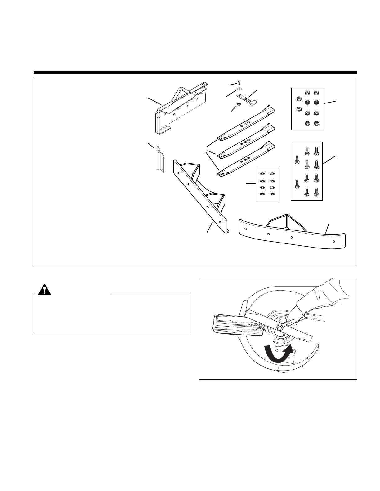
Figure 1. Contents
Kit Contents:
Ref. Part No. Qty. Description
1 1716697 3 BLADES, Mower
2 1726578 1 PLATE, Mounting
3 1732349A 1 BAFFLE ASSEMBLY
4 2171600 1 STRAP, Rubber
5 1933988 8 NUT, Push, 5/16
6 1960096 1 WASHER
7 1960393 1 SCREW, Phillips, #10-24 x 1
8 1933896 1 NUT, Hex, Nylock, #10-24
9 1927557 10 NUT, Hex, Flange Lock, 5/16-18
10 1931332 10 CARRIAGE BOLT, 5/16-18 x 5/8
11 1716150A 1 BAFFLE & DEFLECTOR, LH
12 1726913A 1 BAFFLE & DEFLECTOR, RH
12
INSTALLATION
1. Remove the mower deck. Refer to Operator’s
Manual (see Mower Deck Removal & Installation).
2. See Figure 2. Remove the blades. Use a block of
wood to prevent blade rotation while loosening the
capscrew by turning it counterclockwise.
Before beginning any service work turn off the
PTO, set the parking brake, turn off the ignition,
remove the key, and disconnect the spark plug
wire(s).
WARNING
2
3
7
11
9
10
5
LOOSEN
Figure 2. Blade Removal
4
8
6
1
Page 2
2
Installation Instructions Mulch Kit
A
D
C
E
B
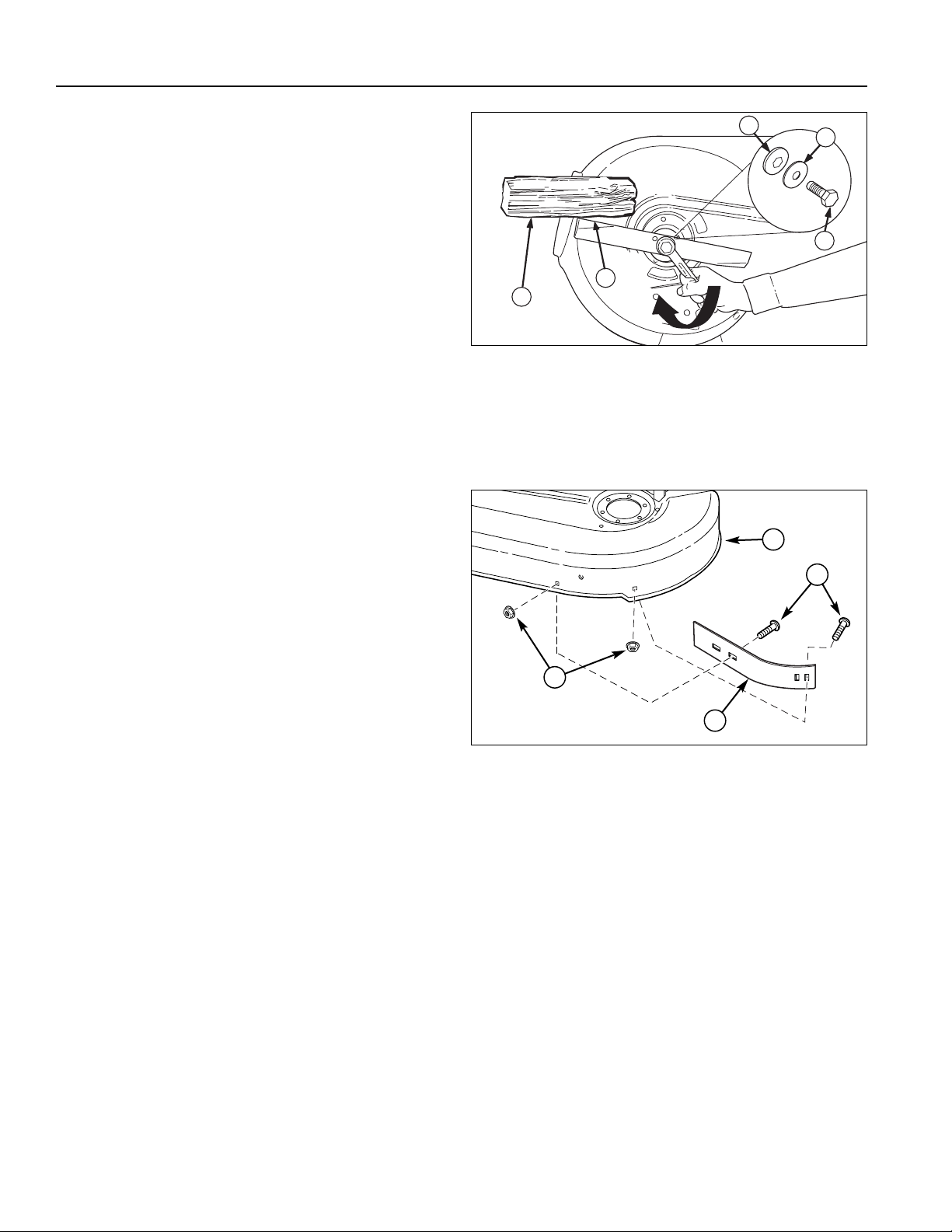
Figure 3. Blade Installation
A. 4x4 Wood Block D. Blade Capscrew
B. Hex Washer E. Blade w/Lift Wings
C. Spring Washer
3. Remove the capscrew (D, Figure 3), spring washer
(C), hex washer (B), and blade (E).
4. Reinstall the new blade with the lift wings (E, Figure
3) pointing up toward the mower deck as shown.
5. Reinstall the hex washer (B, Figure 3), spring washer
(C) and capscrew (D). Use a wooden block (A) to
prevent blade rotation while tightening the capscrew
(D) to 45-55 ft. lbs. (61-75 N.m). Turn capscrew
clockwise to tighten.
Figure 4. Baffle Removal
A. Mower Deck
B. Carriage Bolts,5/16-18 x 3/4
C. Blowout Baffle, Short
D. Nut, Whizlock, 5/16-18 x 3/4
C
B
D
A
6. Remove and discard short blowout baffle (C, Figure
4), carriage bolts (B) and locknuts (D) from mower
deck (A).
Page 3

3
Mulch Kit Installation Instructions
Figure 5. Baffle Installation
A
C
D
E
C
B
B
B
B
C
B
B
B
B
C
C
C
A
B
C
D
Figure 6. Mulch Cover Installation
A. Baffle Assembly
B. Mounting Plate
C. Locknut
D. Discharge Deflector
E. Rubber Strap
7. Install RH baffle (D) and secure with carriage bolts &
push nuts (B) and nuts (C).
Note: The carriage bolt & push nuts are combined to
hold carriage bolt in place and aid in ease of installation.
8. Install mounting plate (A, Figure 5) to mower deck
securing with 5/16-18 x 5/8 carriage bolts (F) nuts.
9. Install LH baffle (E) and secure with carriage bolts &
push nuts (B) and nuts (C).
10. Install the mower deck. Refer to the Operator’s
Manual (see Mower Deck Removal & Installation)
11. Lift discharge deflector up (D, Figure 6).
12. Insert mulch baffle assembly (A) into mounting plate
(B).
13. Pull rubber strap (E) and secure by placing strap
completely over locknut (C).
Note: The new mulching blades DO NOT need to be
removed or changed for side discharge. For use with a
bagger the mulching/side discharge blade will need to be
replaced with a bagging blade.
E
A. Mounting Plate
B. Carriage Bolts & Push Nuts
C. Nut, Flange Lock, 5/16-18
D. Baffle, RH
E. Baffle, LH
F. Carriage Bolts, 5/16-18 x 5/8
C
F
Page 4

4
Installation Instructions Mulch Kit
Form No. 1732615-03
Rev. 4/2006
© 2006 Simplicity Manufacturing, Inc. All Rights Reserved
TP 200-4262-03-AT-SMAN
MANUFACTURING, INC.
500 N Spring Street / PO Box 997
Port Washington, WI 53074-0997 USA
NOTES
 Loading...