

Page 1
07/2007 TP 300-4458-00-LW-SN
Large Frame Snowthrowers
Form No. 1735189
Briggs & Stratton Yard Power Products Group
Copyright © 2007 Briggs & Stratton Corporation
Milwaukee, WI USA. All Rights Reserved
This Dealer Setup Instruction covers the following products:
MANUFACTURING, INC.
Initial setup
L1226E Models
Mfg. No. Description
1695326 SMIL1226E, 11.5GT Snowthrower
1695324 SNL1226E, 11.5GT Snowthrower
1695327 SMIL1226EX, 11.5GT Snowthrower (CE)
1695325 SNL1226EX, 11.5GT Snowthrower (CE)
L1428E Models
Mfg. No. Description
1695330 SMIL1428E, 13.5GT Snowthrower
1695328 SNL1428E, 13.5GT Snowthrower
1695331 SMIL1428EX, 13.5GT Snowthrower(CE)
1695329 SNL1428EX, 13.5GT Snowthrower (CE)
L1530E Models
Mfg. No. Description
1695334 SMIL1530E, 14.5GT Snowthrower
1695332 SNL1530E, 14.5GT Snowthrower
1695335 SMIL1530EX, 14.5GT Snowthrower (CE)
1695333 SNL1530EX, 14.5GT Snowthrower (CE)
L1632E Models
Mfg. No. Description
1695338 SMIL1632E, 15.5GT Snowthrower
1695336 SNL1632E, 15.5GT Snowthrower
1695337 SNL1632EX, 15.5GT Snowthrower (CE)
Page 2
Large Frame Snowthrowers
TP 300-4458-00-LW-SN 07/20072
SAFETY RULES
GENERAL OPERATION
• Read, understand, and follow all instructions in the
manual and on the unit before starting.
• Only allow responsible adults, who are familiar with the
instructions, to operate the unit (local regulations can
restrict operator age).
• Clear the area of objects such as rocks, toys, wire, etc.,
which could be picked up and thrown.
• Be sure the area is clear of other people. Stop unit if anyone enters the area.
• Always look down and behind before and while travelling in
reverse.
• Be aware of the discharge direction and do not point it at
anyone. Do not point the discharge at glass enclosures,
automobiles, or windows.
• Disengage all clutches (release drive and auger control
levers) before starting the engine.
• Never leave a running unit unattended. Always disengage
the auger and traction controls, stop engine, and remove
keys.
• Stop engine before unclogging chute.
• Operate only in daylight or good artificial light.
• Do not operate the unit while under the influence of alcohol
or drugs.
• Watch for traffic when operating near or crossing roadways.
• Use extra care when loading or unloading the unit into a
trailer or truck.
• Keep in mind the operator is responsible for accidents
occurring to other people or property.
• Data indicates that operators, age 60 years and above, are
involved in a large percentage of power equipment-related
injuries. These operators should evaluate their ability to
Read these safety rules and follow them closely. Failure to obey these rules could result in loss of control
of unit, severe personal injury or death to you, or bystanders, or damage to property or equipment.
The triangle in text signifies important cautions or warnings which must be followed.
SLOPE OPERATION
Slopes are a major factor related to loss-of-control and tip-over
accidents, which can result in severe injury or death. All slopes
require extra caution. If you cannot back up the slope or if you feel
uneasy on it, do not operate on it.
Do
• See your authorized dealer for recommendations counterweights to improve stability.
• Travel up and down slopes, not across.
• Remove obstacles such as rocks, tree limbs, etc.
• Watch for holes, ruts, or bumps. Uneven terrain could overturn the unit. Snow can hide obstacles.
• Use slow speed. Tires may lose traction on slopes. Choose
a low gear so that you will not have to stop or shift while on
the slope.
• Keep all movement on the slopes slow and gradual. Do not
make sudden changes in speed or direction.
• Always keep unit in gear especially when traveling downhill.
Do Not
• Do not start or stop on a slope. If tires lose traction, disengage the auger and proceed slowly straight down the
slope.
• Do not turn on slopes unless necessary, and then, turn
slowly and gradually downhill, if possible.
• Do not operate near drop-offs, ditches, or embankments.
The unit could suddenly turn over if a wheel is over the
edge of a cliff or ditch, or if an edge caves in.
• Do not operate on wet surfaces. Reduced traction could
cause sliding.
• Do not shift to neutral and coast down hills.
EMISSIONS
• Engine exhaust from this product contains chemicals
known, in certain quantities, to cause cancer, birth defects,
or other reproductive harm.
• Look for the relevant Emissions Durability Period and Air
Index information on the engine emissions label.
WARNING
Never operate on slopes greater than 17.6 percent (10°) which
is a rise of 3-1/2 feet (106 cm) vertically in 20 feet (607 cm)
horizontally.
When operating on slopes use additional wheel weights or
counterweights. See your dealer to determine which weights
are available and appropriate for your unit.
Select slow ground speed before driving onto slope. Travel UP
and DOWN the slope, never across the face, use caution when
changing directions and DO NOT START OR STOP ON
SLOPE.
operate the unit safely enough to protect themselves and
others from injury.
• All operators should seek and obtain professional and practical instruction.
• Always wear substantial footwear and appropriate winter
clothing. Wear foot-ware that improves traction on slippery
slopes. DO NOT wear long scarves or loose clothing that
could become entangled in moving parts.
• Before using, always visually check that all hardware is
present, in-tact, and secure. Replace worn or damaged
parts.
• Never operate the machine with defective guards, or without safety protective devises in place.
• Stop engine before: refuelling, removing an attachment,
making adjustments (unless the adjustment can be made
from the operator’s position).
• Follow the manufacturer’s recommendation for wheel
weights or counterweights.
• Adjust skid shoe height to clear gravel or crushed rock surfaces.
• Do not touch snowthrower parts which may be hot from
operation. Allow such parts to cool before attempting to
service the unit.
CLEARING A CLOGGED DISCHARGE CHUTE
Hand contact with the rotating impeller inside the discharge
chute is the most common cause of injury associated with
snowthrowers. Always use a clean out tool, not your hands. to
clean out the discharge chute.
To clear the chute:
1. SHUT OFF THE ENGINE.
2. Wait 10 seconds to be sure the impeller blades have
stopped rotating.
3. Always use a clean out tool, not your hands.
Page 3

Large Frame Snowthrowers
07/2007 TP 300-4458-00-LW-SN
Table of Contents
Unpacking . . . . . . . . . . . . . . . . . . . . . . . . . . . . . . . . . . . . . . . . . . . . . . 4
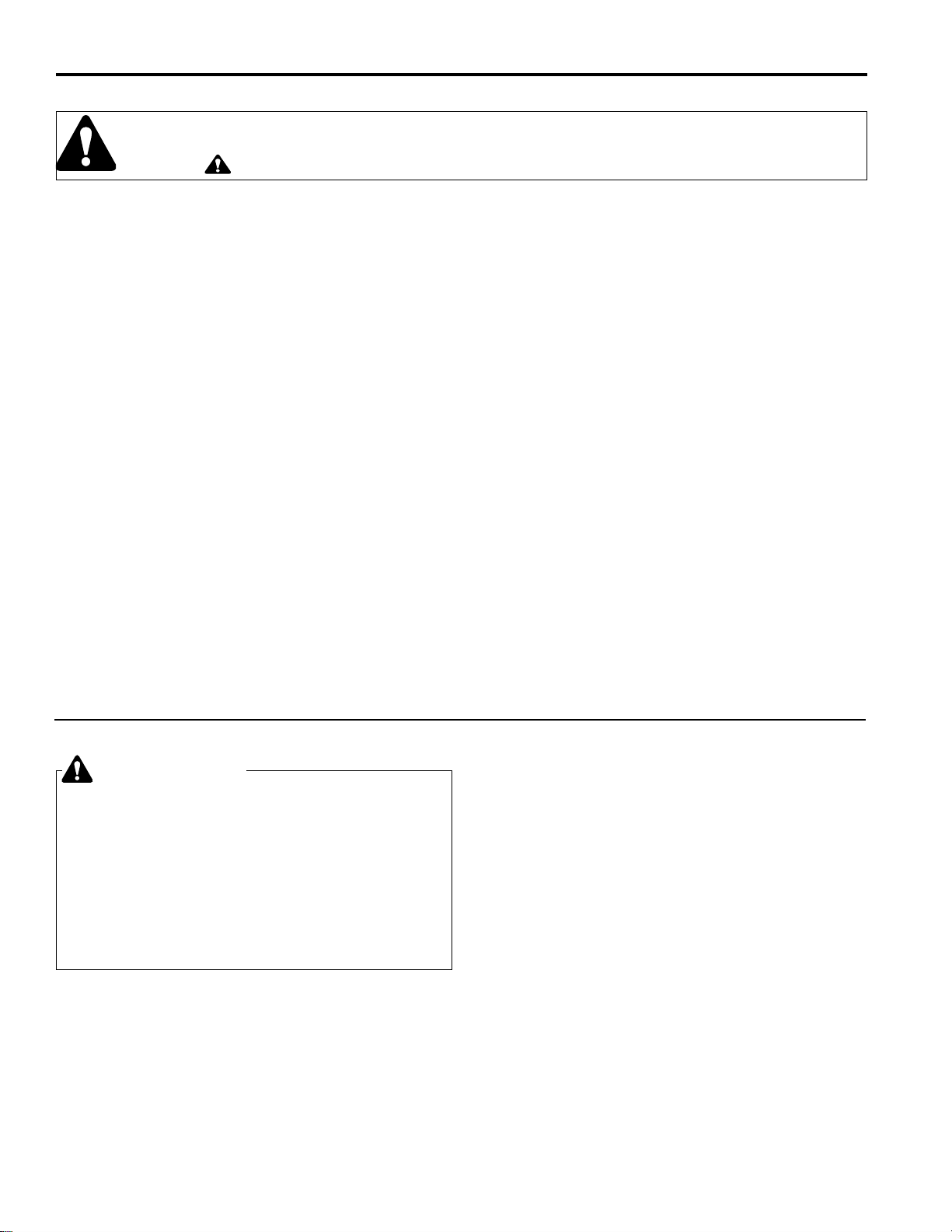
1. Uncrate . . . . . . . . . . . . . . . . . . . . . . . . . . . . . . . . . . . . . . . . . . . . . . . . . . 4
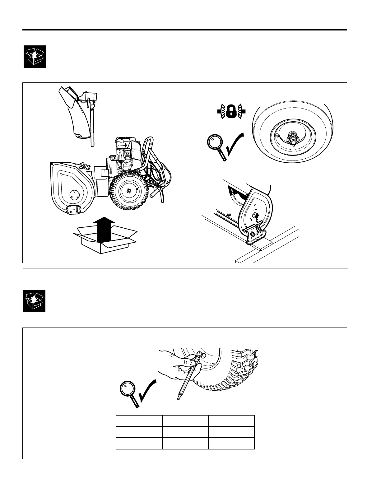
2. Check Tire Pressure . . . . . . . . . . . . . . . . . . . . . . . . . . . . . . . . . . . . . . . . 4
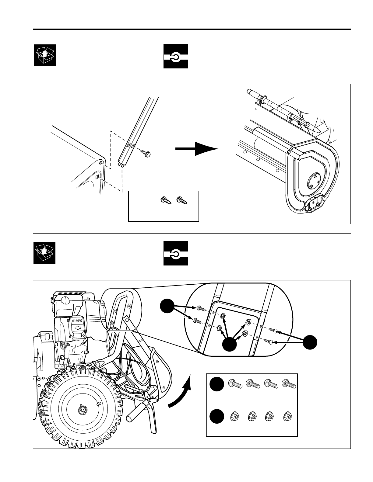
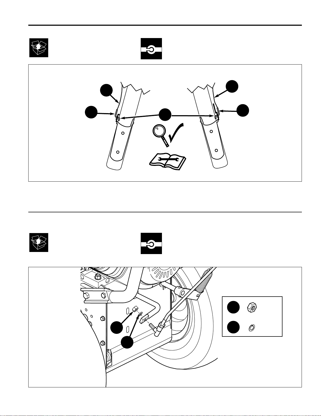
3. Install Drift Cutters . . . . . . . . . . . . . . . . . . . . . . . . . . . . . . . . . . . . . . . . . 5
4. Install Handles . . . . . . . . . . . . . . . . . . . . . . . . . . . . . . . . . . . . . . . . . . . . 5
5. Install Chute . . . . . . . . . . . . . . . . . . . . . . . . . . . . . . . . . . . . . . . . . . . . . . 6
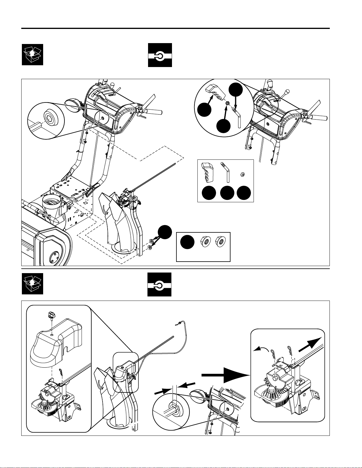
6. Install Chute Rotator Crank. . . . . . . . . . . . . . . . . . . . . . . . . . . . . . . . . . . 6
7. Tube Handle Levers Cable Check . . . . . . . . . . . . . . . . . . . . . . . . . . . . . . 7
8. Connecting Shift Rod . . . . . . . . . . . . . . . . . . . . . . . . . . . . . . . . . . . . . . . 7
9. Chute Rotator Brake Cable Installation . . . . . . . . . . . . . . . . . . . . . . . . . . 7
10. Cable Tie-Wrap Installation . . . . . . . . . . . . . . . . . . . . . . . . . . . . . . . . . . 9
11. Auger Shaft Lubrication . . . . . . . . . . . . . . . . . . . . . . . . . . . . . . . . . . . . 9
12. Auger Drive Lubrication . . . . . . . . . . . . . . . . . . . . . . . . . . . . . . . . . . . . 9
13. Auger Shaft Shear Pins. . . . . . . . . . . . . . . . . . . . . . . . . . . . . . . . . . . . 10
14. Deflector Hinge Lubrication . . . . . . . . . . . . . . . . . . . . . . . . . . . . . . . . 10
15. Axles and Control Lever Lubrication . . . . . . . . . . . . . . . . . . . . . . . . . . 10
16. Spout Rotator Lubrication. . . . . . . . . . . . . . . . . . . . . . . . . . . . . . . . . . 11
17. Hand Control Lubrication . . . . . . . . . . . . . . . . . . . . . . . . . . . . . . . . . . 11
18. Engine Lubrication . . . . . . . . . . . . . . . . . . . . . . . . . . . . . . . . . . . . . . . 11
Perform Safety Checks. . . . . . . . . . . . . . . . . . . . . . . . . . . . . . . . . . . . . 12
Check Engine Controls. . . . . . . . . . . . . . . . . . . . . . . . . . . . . . . . . . . . . . . . 12
Check Snowthrower Controls. . . . . . . . . . . . . . . . . . . . . . . . . . . . . . . . . . . 13
Check Operations. . . . . . . . . . . . . . . . . . . . . . . . . . . . . . . . . . . . . . . . . . . . 13
Adjustments. . . . . . . . . . . . . . . . . . . . . . . . . . . . . . . . . . . . . . . . . . . . 14
Auger Drive Adjustment. . . . . . . . . . . . . . . . . . . . . . . . . . . . . . . . . . . . . . . 14
Traction Drive Adjustment . . . . . . . . . . . . . . . . . . . . . . . . . . . . . . . . . . . . . 14
Speed Drive Adjustment. . . . . . . . . . . . . . . . . . . . . . . . . . . . . . . . . . . . . . . 15
Easy Turn™ Cable Adjustment . . . . . . . . . . . . . . . . . . . . . . . . . . . . . . . . . . 16
Scraper Bar & Skid Shoe Adjustment . . . . . . . . . . . . . . . . . . . . . . . . . . . . 17
Belt Adjustment . . . . . . . . . . . . . . . . . . . . . . . . . . . . . . . . . . . . . . . . . . . . . 18
Belt Replacement . . . . . . . . . . . . . . . . . . . . . . . . . . . . . . . . . . . . . . . . 19
Auger Drive Belt. . . . . . . . . . . . . . . . . . . . . . . . . . . . . . . . . . . . . . . . . . . . . 20
Traction Drive Belt . . . . . . . . . . . . . . . . . . . . . . . . . . . . . . . . . . . . . . . . . . . 20
3
Page 4
Large Frame Snowthrowers
TP 300-4458-00-LW-SN 07/20074
1
2
Size PSI bar
15 x 5.0-6 20 1,38
16 x 4.8-8 14 ,96
(2) x
Page 5
5/16-18 x 2-1/4
5/16-18
Large Frame Snowthrowers
07/2007 5 TP 300-4458-00-LW-SN
3
5/16-18 x 3/4
B
B
4
A
A
A
Page 6
>= 3/8” (9.5mm)
Large Frame Snowthrowers
TP 300-4458-00-LW-SN 07/20076
6
5
3/8-16
A
BAC D
B
C
D
Page 7
Large Frame Snowthrowers
07/2007 7 TP 300-4458-00-LW-SN
7
3
2
2
1
1
5/16
5/16
8
A
B
A
B
Page 8

Large Frame Snowthrowers
TP 300-4458-00-LW-SN 07/20078
9
1 2
3 4
Page 9

Large Frame Snowthrowers
07/2007 9 TP 300-4458-00-LW-SN
10
5
11 12
Page 10

Large Frame Snowthrowers
TP 300-4458-00-LW-SN 07/200710
13
14 15
Page 11

Large Frame Snowthrowers
07/2007 11 TP 300-4458-00-LW-SN
18
16 17
Page 12

Large Frame Snowthrowers
TP 300-4458-00-LW-SN 07/200712
Perform
Safety Checks
Check Engine Controls
1. Make sure all safety guards are in place and all nuts,
bolts, clips, cotter pins and wires are secure.
2. Check to make sure spark plug wire is attached.
3. Check all controls for proper operation:
a. The engine should stop when the key is removed.
b. The throttle should control the engine speed and
stop the engine when moved to the STOP position.
c. The fuel shut-off valve should stop the flow of fuel
to the engine
d. The recoil starter or electric starter (if equipped)
should crank the engine when activated.
4. Check the engine area for oil or gasoline leaks.
Correct any problems in accordance with the engine
manufacturers instructions.
Figure 1. Engine Controls
A. Electric Start Button
B. Fuel Valve (Select Models)
C. Starter Handle
D. Primer Button
E. Throttle Lever (Snow Max Models Only)
F. Engine Key
G. Choke Knob
H. Stop Switch
Snow
Series
C
D
F
B
G
A
H
C
G
A
E
B
F
D
Snow
Max
Page 13

Large Frame Snowthrowers
07/2007 13 TP 300-4458-00-LW-SN
Check Snowthrower Controls
1. Check the skid shoes to make sure they are set at the
desired height. Adjust if necessary.
2. Check the traction drive control (B, Figure 2).
Snowthrower motion should stop when the control is
released.
3. Check the auger control (C). Auger movement should
stop when the control is released.
4. Check the manual chute direction control (D) for proper operation. The discharge chute should rotate freely
in both directions.
5. Check the remote deflector control (E) for proper
operation. The deflector should pivot freely up and
down when the chute deflector control (E) is pushed
to the left and either moved forward or backward.
6. Check the speed selector (A) for smooth operation.
The control must move freely into each speed position gate and remain in position when released.
If controls do not function properly, perform the
appropriate adjustment as shown in the
Adjustment Section.
7. The auger is secured to the shaft by shear pins,
which will break if the auger strikes an object. Extra
shear pins are provided. Keep these pins in the compartment on the belt cover. Lubricate the auger shaft.
Check Operations
1. With engine at full speed, engage the auger control
and release. Do this ten (10) times. Auger should
come to a complete stop within five seconds each
time. If not, perform Auger Adjustments.
3. Engage traction control and release. Do this ten
times. Unit should come to a complete stop each
time. If it does not, perform the Traction Drive
Adjustments.
4. Remove the engine key. The engine must stop.
5. Move the throttle to STOP or push the stop switch.
The engine must stop.
Figure 2. Controls (from operator’s position)
A. Speed Selector
B. Traction Control & Free-Hand™ Control
C. Auger Engage Control
D. Chute Rotator Control
E. Remote Deflector Control
F. Easy Turn Lever
E
Perform
Safety Checks
A
B
C
D
F
Page 14

Large Frame Snowthrowers
TP 300-4458-00-LW-SN 07/200714
WARNING
Do not over-tighten, as this may cause traction
drive to engage without depressing the traction
drive control (arm must remain in down position).
Verify that the cables are not over-tightened: With
speed selector in position 1 and traction drive
control fully released, push snowthrower forward.
The unit should move forward freely.
If unit does not move forward freely, the cable has
been over-tightened. To remedy, loosen tension
on clutch cable slightly, and recheck.
1. Check that the auger cable (A, Figure 3) is on top of
cable button (B) as shown in Figure 3.
2. With the drive lever released, the hook (B, Figure 4)
should barely touch the lever (C) without raising it.
There can be a maximum 1/32” clearance as shown.
3. To adjust, loosen nut (D) by holding the adjusting
flats (A) and turning nut (D). Turn adjustment flats
and hold screw. The adjustment screw (E) is a
phillips screw and the head can be held or turned by
inserting a screwdriver through the spring (F).
4. Hold adjusting flats (A) and tighten nut (D).
5. Start unit and check auger. Auger must not be
engaged unless auger control is depressed.
6. With engine running, fully depress auger control, the
auger should engage and run normally.
7. Release auger control. Auger must stop within 5
seconds.
8. If auger does not operate properly, stop engine and
recheck drive linkage adjustments.
9. If auger linkage is properly adjusted, auger drive belt
tension may require adjustment. See adjusting the
auger belt in this section of the manual
WARNING
Do not over-tighten, as this may lift the lever and
cause auger drive to be engaged without
depressing the Auger Control.
A
B
C
D
E
F
1/32” (.8 mm)
Figure 4. Auger Drive Adjustment
A. Adjusting Flats
B. Spring Hook
C. Lever
D. Adjustment Nut
E. Adjustment Screw
F. Spring
TRACTION DRIVE ADJUSTMENT
Initial Adjustment
Auger Drive
Adjustment
1. With the drive lever released there should be slack in
the cable when moved slightly from side to side.
2. To adjust tension on the cable slide the cable boot (A,
Figure 5) off the cable adjustment bracket (D).
3. Move the “Z” hook (C) from the cable adjustment
bracket (D) to a different adjustment hole. The cable
should have slack. The cable should have no tension
or load.
Figure 3. Auger Cable Button
A. Auger Drive Cable
B. Auger Cable Button
C. Lever
A
B
C
Page 15

Large Frame Snowthrowers
07/2007 15 TP 300-4458-00-LW-SN
Figure 5. Traction Drive Cable Adjustment
A. Cable Boot
B. Traction Drive Cable
C. “Z” Hook
D. Cable Adjustment Bracket
C
A
B
D
B
C
Run-In Adjustment
ALL MODELS
1. After 5 hours of use, check for proper adjustment.
Readjust clutch cable if necessary by increasing tension on cable. A small amount of arm movement is
permissible if unit passes operating checks described
in the Warning above.
WARNING
Gasoline is highly flammable and must be
handled with care. Drain gasoline outdoors. Never
drain the tank when the engine is still hot from
recent operation. Do not allow open flame,
smoking or matches in the area. Avoid over-filling
and wipe up any spills.
Figure 6. Bottom Cover
A. Capscrews
B. Bottom Panel
C. Auger Housing
C
B
A
A
Note: If the cable is too slack the unit will not drive. If the
cable is too tight the drive will be engaged without
pushing the handle down.
4. Slide the cable boot (A) over the cable adjustment
bracket.
SPEED DRIVE ADJUSTMENT
1. Remove the gas from the gas tank.
2. Disconnect the spark plug wire.
3. Stand snowthrower on the front of the auger housing
(C, Figure 6).
4. Remove the capscrews (A) on each side of the
bottom panel (B).
5. Remove the bottom panel (B).
6. Position the shift speed lever in the lowest forward
speed.
7. Note the position of the friction wheel (A, Figure 7).
The correct distance from the right side of the friction
wheel to the outside of the frmae is 4-5/16” (10.95
cm). If the friction wheel is not in the correct
postition, adjust as follows.
A
B
Figure 7. Friction Disc Measurement
A. Friction Disk
B. Frame
4-5/16”
(10.95 cm)
Page 16

Large Frame Snowthrowers
TP 300-4458-00-LW-SN 07/200716
Figure 8. Speed Selector Linkage
A. Speed Selector Rod
B. Jam Nut
C. Ball Joint
D. Locknut
E. Shift Rod
A
8. Loosen the jam nut (B, Figure 8).
9. Remove locknut (D).
10.Move the friction wheel (A, Figure 7) to the correct
distance 4-5/16” (10.95 cm).
11.Turn the ball joint (C, Figure 8) until it is aligned with
the mounting hole in the shifter rod (E). When
aligned, attach the ball joint (C) to the shifter rod (E)
and tighten the jam nut (B) and locknut (D).
12.Check that the snowthrower operates in R1. If not
follow procedures 1-11 and readjust as necessary.
13.Install the bottom panel (B, Figure 6) and tighten the
capscrews (A).
B
C
D
E
EASY TURN™ CABLE ADJUSTMENT
If the Easy Turn™ cable has stretched, the gears will not
disengage when the control lever is activated. Adjust the
cable using the following procedure.
1. Turn the engine off and disconnect the spark plug
wire.
2. Loosen the jam nut (B, Figure 9).
3. Turn the adjustment nut (A) to lengthen or shorten
the cable. The cable should be tightened just until all
slack is removed from the lever, however it must not
engage the Easy Turn™ release without depressing
the control lever.
4. Tighten the jam nut.
A
B
Figure 9. Easy Turn™ Cable Adjustment
A. Adjustment Nut
B. Jam Nut
Page 17

Large Frame Snowthrowers
07/2007 17 TP 300-4458-00-LW-SN
Figure 10. Skid Shoe Adjustment
A. Scraper Bar
B. Skid Shoe
C. Nuts
A
B
C
On smooth surfaces such as concrete or asphalt, the
scraper bar should scrape the surface. On surfaces such
as gravel, the scraper bar should be high enough so that
it will not pick up gravel or debris.
The height of the scraper bar is controlled by raising or
lowering the Skid Shoes (See Figure 10).
1. To raise the scraper bar height, rest the scraper bar on
a strip of wood equal in thickness to the desired height.
2. Make sure the scraper bar is parallel to the ground
surface.
3. Loosen the skid shoe nuts and let the skid shoes drop
to the surface.
4. Tighten the nuts, making sure the Skid Shoes are
adjusted equally and are parallel to the surface.
5. To lower the height of the scraper bar, raise the Skid
Shoes.
6. If the scraper bar becomes worn, it can be adjusted
by loosening the nuts and bolts attaching it to the
snowthrower, making the adjustment, and tightening
the hardware. It may also be replaced by removing
the mounting nuts and bolts attaching it to the
snowthrower.
Scraper Bar &
Skid Shoe Adjustment
Page 18

Large Frame Snowthrowers
TP 300-4458-00-LW-SN 07/200718
Figure 11. Belt Cover
A. Belt Cover
B. Screws
A
B
B
Figure 12. Auger Belt Deflection
A. Engine Drive Pulley
B. Idler Pulley (Engaged Position)
C. Auger Drive Pulley
D. Nut
E. Auger Belt
B
C
A
1/2” (12.5mm)
Deflection
Auger Drive Belt
If your snowthrower will not discharge snow, check the
control cable adjustment. If it is correct, then check the
condition of the auger drive belt. If it is damaged or
loose,replace it (see Belt Replacement in this section of
the manual).
1. Disconnect spark plug wire.
2. Loosen screw (B, Figure 11) from belt cover (A).
Remove belt cover (A).
3. Loosen nut (D, Figure 12) on auger idler pulley (B)
and move auger idler pulley towards belt about 1/8
inch (3mm).
4. Tighten nut (D).
5. Engage auger drive clutch. Check tension on belt
(opposite idler pulley). Belt should deflect about 1/2
inch (12.5 mm) with moderate pressure see Figure
12). You may have to move the idler pulley more
than once to obtain the correct tension.
6. Reinstall belt cover (A, Figure 11) securing with
screws (B).
7. Whenever belts are adjusted or replaced, the auger
drive or traction drive controls will need to be
adjusted. (see Auger Drive or Traction Drive
Adjustment in this section of the manual).
8. Attach the spark plug wire.
9. Auger must stop within 5 seconds.
Traction Drive Belt
The traction drive belt has constant spring pressure and
does not require an adjustment. If the traction drive belt
is slipping,replace the belt. See Belt Replacement.
Note: After adjustments are complete, make sure the
drive disengages when released.
D
E
Belt Adjustment
Page 19

Large Frame Snowthrowers
07/2007 19 TP 300-4458-00-LW-SN
Belt Replacement
Auger Drive Belt
The drive belts are of special construction and must be
replaced with original factory replacement belts available
from your nearest authorized service center. Some
steps require the assistance of a second person. If the
auger drive belt is damaged, the snow thrower will not
discharge snow. Replace the damaged belt as follows.
1. Disconnect the spark plug wire.
2. Remove the capscrews (A, Figure 13) on each side
of the bottom panel (B).
3. Remove the bottom panel (B).
I
J
Figure 14. Pulleys and Belts
A. Traction Drive Belt
B. Belt Guide
C. Auger Drive Pulley, Engine
D. Auger Drive Belt
E. Traction Drive Spring
F. Traction Drive Pulley, Engine
G. Traction Drive Pulley
H. Impeller Pulley
I. Swing Plate Axle Rod
J. “E”-Ring
K. Auger Idler Pulley
L. Traction Drive Idler Pulley
Figure 13. Bottom Cover
A. Capscrews
B. Bottom Panel
C. Auger Housing
C
4. Loosen screws (B, Figure 11) from belt cover (A).
Remove belt cover (A).
5. Loosen the belt guide (B, Figure 14). Pull the belt
guide away from the auger drive pulley (C).
6. Pull the auger idler pulley (K) away from the auger
drive belt (D) and slip the belt off of the idler.
7. Remove the auger drive belt (D) from the engine pulley. To remove the auger drive belt (D), the auger
drive pulley (C) may have to be partially rotated.
8. Index or point the spout to the center of the machine
so that the rotator control is in the center of the dash
panel.
A
A
B
H
G
A
E
D
C
B
A
F
L
K
Page 20

Large Frame Snowthrowers
TP 300-4458-00-LW-SN 07/200720
Figure 16. Frame and Axle Housing
A. Upper Capscrews
B. Lower Capscrews
C. Auger Housing
D. Frame
B
Figure 15. Spout Rotator Rod
A. Special Nut
B. Cover
C. Hair Pin
D. Spout Rotator Rod
A
B
C
D
A
B
D
A
D
C
Figure 17. Install Spout Rotator Rod
A. Hex Dash Opening
B. Spout Rotator Rod
9. Remove special nut (A, Figure 15) and cover (B).
10.Remove hair pin (C) and slide rod forward about 3
inches until hex shaft separates from the handle
control.
11.Remove the upper four capscrews (A, Figure 16) that
hold together the auger housing (C) and the frame
(D). Loosen the lower two capscrews (B). The auger
housing (C) and the frame (D) can now be split apart
for removal of the belt.
12.Remove the old auger drive belt (D, Figure 14) from
the impeller pulley. Replace the auger drive belt with
an original factory replacement belt (available from
an authorized service center).
13.Install the new auger drive belt (D) onto the impeller
pulley (H).
NOTE: To assemble the auger housing to the frame,
have someone hold the auger clutch lever in the
ENGAGED position. This will move the idler arm and pulley enough to allow the auger drive pulley to move back
into position.
14.Assemble the auger housing (C, Figure 16) to the
frame with the four upper capscrews (A) that were
removed in step 11. Tighten the two lower capscrews
(B)
15.Index or point the spout rotator to the center of the
machine so the rotator control is in the center of the
dash panel.
A
B
A
B
16.Slide spout rotator rod (B, Figure 17) into hex dash
opening (A).
17.Insert hair pin (C, Figure 15) into spout rotator rod (D).
18.Install cover (B) and secure with special nut (A).
19.Install the auger drive belt (D, Figure 13) onto the
engine pulley (C).
20.Slip the auger drive belt (D) under the idler pulley (K).
21.Adjust the auger drive belt. See “How To Adjust The
Auger Drive Belt” in the Service section.
Page 21

Large Frame Snowthrowers
07/2007 21 TP 300-4458-00-LW-SN
22.Adjust the belt guide. See “Belt Adjustment” in the
Adjustment section.
23.Install the belt cover (A, Figure 11). Tighten screws
(B).
24.Check the adjustment of the cables. See “Drive
Adjustments” in the Adjustment section.
25.Install the bottom panel (B, Figure 13).
26.Tighten the capscrews (A) on each side of the bottom
panel (B).
27.Connect the spark plug wire.
28.Test for proper operation and re-adjust the controls as
needed.
Traction Drive Belt
If the snow thrower will not move forward, check the traction drive belt for wear or damage. If the traction drive
belt is worn or damaged, replace the belt as follows.
1. Disconnect the spark plug wire.
2. Remove the auger drive belt. See “Belt Replacement”
in this section.
3. Remove the traction drive spring (E, Figure 14).
4. Remove the e-ring (J, Figure 14) from one end of the
swing plate axle rod (I).
5. Remove the swing plate axle rod (I) to allow the
swing plate (A, Figure 14) to pivot forward.
6. Remove the old traction drive belt (A) from the traction drive pulley (G) and from the traction drive pulley
(F). Replace the traction drive belt (A) with an original factory replacement belt available from an
authorized Dealer.
7. Install the new traction drive belt (A) onto the traction
drive pulley (G) and onto traction drive pulley (F).
8. Make sure the traction drive idler pulley (L) is properly aligned with the traction drive belt (A).
9. Install the swing plate axle rod (I) and secure with the
e-ring (J) removed earlier.
10.The bottom of the swing plate (A, Figure 18) must be
positioned between the alignment tabs (B). Make
sure the swing plate is properly secured.
NOTE: If the drive will not engage after the traction drive
belt has been replaced, then check to make sure that the
swing plate is positioned between the alignment tabs.
11.Attach the traction drive spring (E, Figure 14).
12.Install and adjust the auger drive belt. See Belt
Replacement in this section of the manual.
13.Adjust the belt guide. See “Belt Adjustment” in the
adjustment section of the manual.
14.Install the bottom panel (B, Figure 13). Tighten 1/420 screws to 25-35 lb-in (2,8-3,9 Nm).
15.Install the belt cover (A, Figure 11). Tighten 1/4-20
screws (B) to 25-35 lb-in (2,8-3,9 Nm).
Note: Caution must be taken when tightening the screws
that secure the belt cover. Over tightening the screws
will deform the plastic.
16.Check the adjustment of the cables. See “Drive
Adjustments” in the Adjustment section.
17.Connect the spark plug wire.
Figure 18. Traction Belt Change
A. Swing Plate
B. Alignment Tabs
A
B
Page 22

Large Frame Snowthrowers
TP 300-4458-00-LW-SN 07/2007
MANUFACTURING, INC.
500 N Spring Street / PO Box 997
Port Washington, WI 53074-0997
www.SimplicityMfg.com
PRODUCTS
535 Macon Street
McDonough, GA 30253
www.Snapper.com
Briggs & Stratton Yard Power Products Group
Copyright © 2006 Briggs & Stratton Corporation
Milwaukee, WI USA. All Rights Reserved
 Loading...