

Page 1

How to use this file...(Installation Instruction Sheets)
————————————————————————————————————————————–––
Instructions for
Print Vendors (Paper Manuals)
Paper: * Finish Size is 8-1/2 x 11
* Body—50 lbs brilliant white offset or equivalent.
Press: * Body—1-color, 2-sided
Bindery: * If document is 1 or 2 pages, run as 8-1/2 x 11 sheets.
* If document is 3 or 4 pages, and can be run as 2 sided 11 x 17 -- then fold to 8-12 - 11.
* If document is MORE than 4 pages, run as 8-1/2 x 11 sheets with UL Corner Stitch.
COVERS: * This document is a self-covered piece.
• Check the last page of the document for the individual document number
(a TP 200-XXXX-XX-XX-SMA number).
BODY: * REMEMBER: ODD number pages are ALWAYS right hand pages, and EVEN number are ALWAYS
left hand pages.
General: * This instruction page is NOT part of the document and must NOT be printed.
• Pages labeled with the text “THIS PAGE INTENTIONALLY BLANK” are placement pages ONLY,
and should NOT be printed.
————————————————————————————————————————————–––
If you have further questions on how to utilize this file, please contact
Simplicity Technical Publications Department at (414) 284-8650.
Page 2
1
Installation
Instructions
Update Kit
For 520 Series & Snow Tackler™
Single Stage Snowthrowers
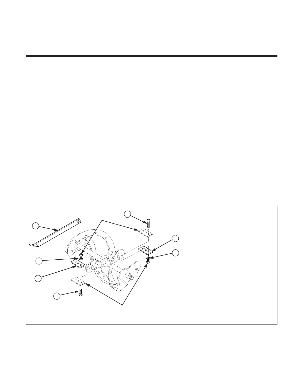
Ref Part No. Qty. Description
1 1716661 2 FLIGHTING, Center
2 1960353 6 WASHER
3 1928745 6 CAPSCREW, Hex Hd, 1/4-20 x 1 1/4 Lg
4 1718507 1 STRAP, Support
Extended reliability and durability testing of the new 520
single stage snowthrowers indicates that the life of the
auger drive system is significantly improved by doubling
the material used in the auger center section.
Based on these test results, we have added a second
center section to the auger, and a support strap to the
auger housing on all units produced during and after
October 1997.
Because the auger drive performance is significantly
improved by these enhancements, we desire to have
ALL units updated to include these enhancements.
Please update all units in your stock, and contact all
customers to whom you have delivered a 520 or Snow
Tackler (They may bring the unit in for you to update, or
they may perform the update themselves — it is a simple
15 minute procedure.)
And remember to inform your customers that these
double center sections can be reversed to extend drive
life even further.
UNITS AFFECTED:
Mfg. No. Description
1692614 520E Compact Snowthrower
1692917 520M Compact Snowthrower
1692918 520E Compact Snowthrower
1693166 520M Compact Snowthrower (Export)
1692977 Green Bay Packers Snowthrower
1692978 Minnesota Vikings Snowthrower
1692979 Chicago Bears Snowthrower
1692980 Detroit Lions Snowthrower
1692981 Pittsburgh Steelers Snowthrower
1692984 New England Patriots Snowthrower
1692985 New York Jets Snowthrower
1692986 St. Loius Rams Snowthrower
1692991 Cleveland Browns Snowthrower
1692992 New York Giants Snowthrower
Kit Contents:
1
1
2
2
4
3
3
Existing
Parts
Existing
Parts
Page 3

Install Flighting
❶ Step One — Loosen the nuts securing the three
bolts which hold the center flighting onto the auger.
retain the nuts and lockwashers, but discard the bolts.
❷ Step Two — See Kit Contents Illustration on page 1.
Position the ADDITIONAL center flights on the
OPPOSITE SIDE from the existing flighting. Attach these
to the auger with the the new bolts provided. Secure the
flights with the nuts and lockwashers from step 1.
Remove Cover
❸ Step Three — remove the cover as follows:
a. Remove the Engine Key from the switch.
b. Remove the two rear fasteners securing the back of
the cover housing. (Figure 2).
c. Remove the fuel tank cap.
d. Remove the cover (see Figure 3).
e. Temporarily reinstall the fuel tank cap.
Install Support Strap
❹ Step Four —See Figure 4. Loosen and remove the
capscrews at locations (A) and (B). Retain the hardware.
❺ Step Five — Attach the support strap supplied in
this kit as shown in Figure 4. The strap is attached to the
outside of the handle at locat (A), and ont top of the
housing at location (B). Secure with the capscrews,
lockwashers, and nuts saved from Step 4.
Reinstall Cover
❻ Step Six — Reinstall the cover by reversing the
removal steps.
Make certain that the tabs at the lower
front of the cover are positioned correctly, and that the
cover is properly seated.
Figure 4. Support Strap Installation
Figure 1. Flighting Installation
Update Kit
Figure 3. Cover Removal & Installation
Insert front
tabs first when
reinstalling
cover.
Align rear
tabs & side of
cover when
reinstalling.
Lift Cover
from Rear
of unit
A
B
Figure 2. Remove and/or loosen Cover Screws
Remove two
rear fasteners
securing
cover
Remove
Fuel Tank
Cap
Support Strap
1718357
Rev. 11/97
© 1997 Simplicity Manufacturing, Inc. All Rights Reserved
TP 200-2121-01-SK-S
MANUFACTURING, INC.
500 N Spring Street / PO Box 997
Port Washington, WI 53074-0997 USA
Loosen
Nuts
Additional
Flighting
Additional
Flighting
❶ ❷
 Loading...