

Page 1

Service Manual for X9.5 and Older Models
Page 2

I. Common Issues .......................................................................... 2
Table of Contents
A. Direct Air Motor.................................................................................. 2
A.1. Direct Air Motor will not run. ................................................... 2
A.2. Direct Air Motor is making a squealing sound. ..................... 2
B. Full Bag Indicator (FBI) ..................................................................... 3
B.1. Full bag light will not come “ON”. .......................................... 3
B.2. Bag is full but the FBI did not come “ON”. ............................ 3
B.3. Bag is not full and the FBI light is on. .................................... 3
C. General Issues: ................................................................................. 4
C.1 Why does the dust cover gap open when the lower
motor is turned “ON”? ............................................................... 4
C.2. The vacuum does NOT run but the lights in the handle
switches are on. .......................................................................... 4
C.3. Identifying Models by PCB Layout or Belt Idler Assembly ... 5
II. Maintenance Procedures .......................................................... 6
A. Disassembly Instructions................................................................... 6
B. Removing the Brush Strips................................................................ 8
C. Replacing the Belt ............................................................................. 9
D. Replacing the LED Light Board ....................................................... 10
E. Replacing the Spring Assist Assembly ............................................ 10
F. Replacing the Main PC Board...........................................................11
G. Replacing the Clean Air Motor ........................................................ 12
H. Installing the Motor Cover ............................................................... 13
I. Removing and Replacing the Direct Air Motor .................................. 14
J. Replacing the Direct Air Motor Fan .................................................. 16
K. Replacing the Rear Wheels............................................................. 18
L. Replacing the Tilt Lock Pedal Spring ............................................... 18
III. General Troubleshooting ....................................................... 19
A. Vacuum has no power. .................................................................... 19
B. Direct Air Motor Will Not Run........................................................... 21
B.1. Direct Air Motor Will Not Run: No Headlights ............................ 21
B.2. Direct Air Motor Will Not Run: Headlights are on ...................... 22
C. Nozzle Suction Power is Weak ....................................................... 24
C.1. There is no suction at the hose ................................................. 24
C.2. There is no suction at the nozzle .............................................. 24
D. Excessive Vibration ......................................................................... 25
E. Agitator/brushroll Does Not Rotate .................................................. 25
F. Agitator/brushroll Jam Test .............................................................. 26
IV. Trouble Shooting - .4 and Older Models Only ...................... 27
A. Full Bag Indicator (FBI) Comes On Too Soon or Not At All ............. 27
B. Agitator/brushroll Jam Light Comes On Too Soon or Not At All ....... 28
V. Trouble Shooting - .5 and .6 Models Only ............................. 29
A. Direct Air Motor Starts But Shuts Off in 2 or 3 Seconds .................. 29
B. The Full Bag Indicator will ash On when the vacuum is shut Off. . 29
VI. Figures
A. Correct Handle Installation ................................................................ 4
B. PCB Layout and Belt Idler Assembly.................................................5
C. Location of Nozzle Cover Screws ..................................................... 6
D. Agitator/Brushroll Assembly .............................................................. 8
E. Belt Placement .................................................................................. 9
F. Clean Air Motor Wiring ..................................................................... 12
G. Ametek Clean Air Motor Wiring ....................................................... 12
H. Clean Air Motor Placement ............................................................. 12
I. Handle to Body Harness Connector ................................................. 19
J. Location of Winged Rocker Switch .................................................. 22
K. Location of Micro Switch .................................................................22
L. Proper Position for Tools Activation Dial/Rotational Valve Handle ... 23
M. Agitator/brushroll Jam Screw - FBI Screw Position ........................ 27
N. Handle Assembly ............................................................................ 30
O. Body Assembly ............................................................................... 31
P. Nozzle Assembly .............................................................................32
Q. Handle Wiring .................................................................................33
R. Main Body Wire Harness .5 and .6 Models ..................................... 34
S. Main Body Wire Harness .4 and Older Models ............................... 35
T. Description of Vacuum ..................................................................... 36
Page 3

IMPORTANT SAFETY INSTRUCTIONS
When using or servicing any electrical appliance, basic precautions should always be
followed, including the following:
WARNING: To reduce the risk of re, electrical shock, or injury:
1. Do not leave vacuum unattended when plugged in. Unplug from outlet when not in use.
2. Turn off all controls before unplugging.
3. Do not attempt to service vacuum while plugged in.
4. Before handling PC board, discharge static electricity by using anti-static mat and
ground strap. If anti-static mat is not available, touch a metal object that is grounded and
only handle PC board by outside edges.
WARNING: ELECTRIC SHOCK COULD OCCUR IF USED OUTDOORS OR ON WET SURFACES.
Page 4

I. Common Issues
A. Direct Air Motor
A.1. Direct Air Motor will not run.
Check the following:
1. The main switch must be “ON” and the oor/carpet switch must be in the carpet position.
2. The tools activation dial/rotational valve handle must be in the tools “OFF” position.
3. The vacuum must be out of the upright position (controlled by the wing rocker switch) unless the nozzle cover is off.
4. The clean air motor must have 12 to 18 volts going to the PC board via the blue/yellow tap wire.
5. The headlights should be on. This assures that the fuses on the PC board are working and there is power in the tap wire. (See
Figure B. PCB Layout and Belt Idler Assembly)
NOTE: All the above conditions must be met on .4 and older models. .5 and newer models must also have the belt installed
belt for the hall sensor to work, other wise the direct air motor will come on for 2 to 3 seconds then shut “OFF”.
A.2. Direct Air Motor is making a squealing sound.
Check for the following conditions:
1. The motor has been changed and the seals are out of place or the motor is not seated properly.
2. The bearings are damaged.
3. Hair or thread is wrapped around the motor shaft and the bearing under fan.
071807 I. Common Issues
2
Page 5

B. Full Bag Indicator (FBI)
B.1. Full bag light will not come “ON”.
The full bag indicator is controlled by temperature. As the bag lls, the air ow is restricted causing the motor to work harder building up
heat in the motor compartment. At a set point, this heat build up causes the FBI to illuminate. It may take up to 2 minutes for the FBI
light to illuminate. If the airow is not completely blocked off, the temperature may not reach the point needed to turn on the FBI light.
Additionally, if the bag has been lled with uffy type material such as carpet ber, the air ow may not be restricted enough to cause the
motor to build up heat.
To test the FBI system:
1. The air ow must be completely blocked off.
2. Place the tool activation dial/rotational valve handle to the tools “ON” position.
3. Blocking off the hose the FBI light should illuminate with in 2 minutes.
B.2. Bag is full but the FBI did not come “ON”.
Check the bag for content. If the bag is full of carpet ber or other uffy material the air ow may not be restricted enough to cause the
motor to heat up and the light to illuminate.
B.3. Bag is not full and the FBI light is on.
The FBI light will illuminate if the pores of the HEPA bag become clogged with a ne powder type substance, such as drywall dust.
This is the most common reason for the light to illuminate.
071807 I. Common Issues
3
Page 6
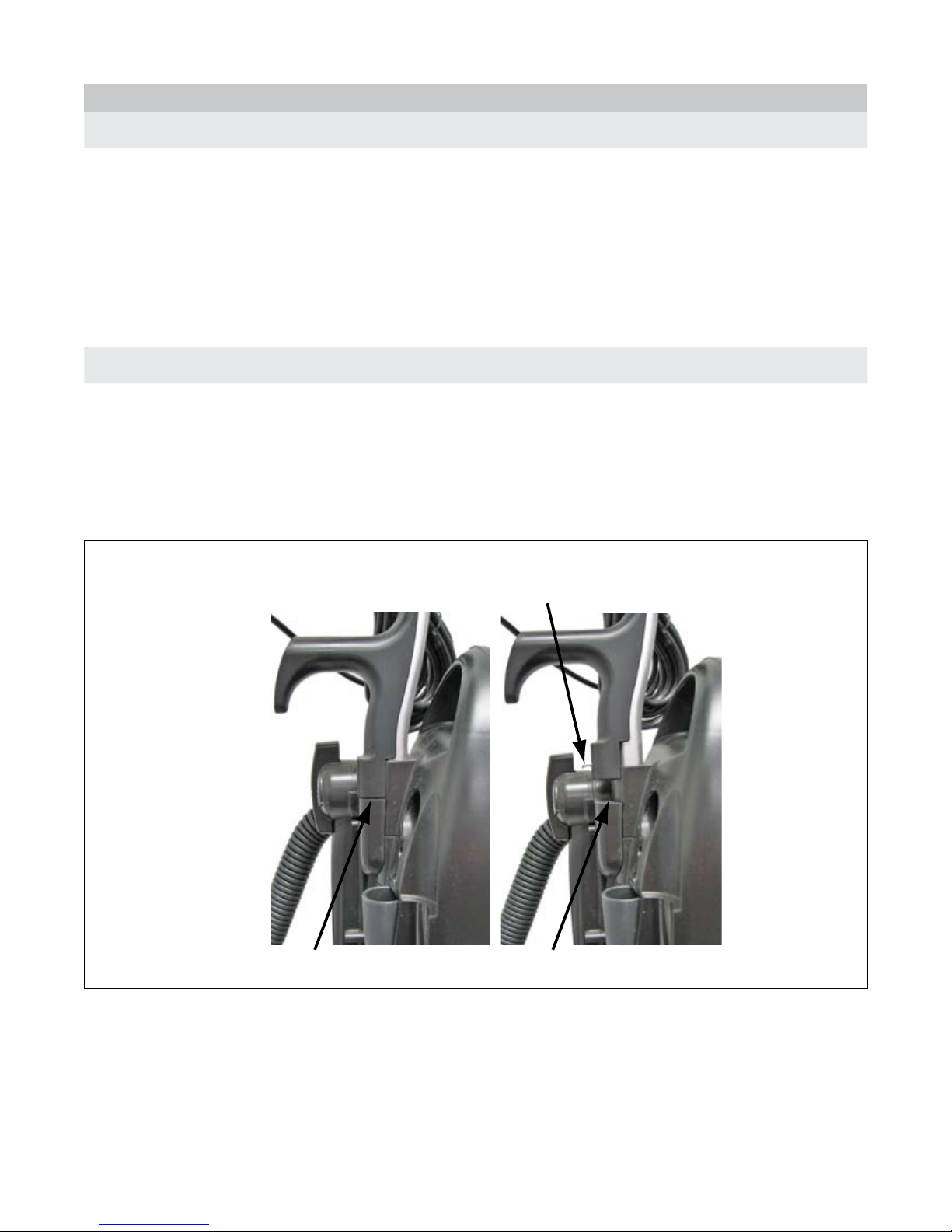
C. General Issues:
Correctly Installed Handle
Incorrectly Installed Handle
Remove handle screw before installing handle
C.1 Why does the dust cover gap open when the lower motor is turned “ON”?
The direct air motor pulls more air into the dust compartment than the clean air motor can push out. This could be caused by the
following:
1. The nozzle is not sitting on the oor; therefore the airow is not restricted and will push the cover open.
2. The HEPA lter may be clogged, causing back pressure.
3. The bag inlet seal may be torn allowing air to bypass the HEPA bag, increasing the airow so the clean air motor cannot relieve all
the pressure.
C.2. The vacuum does NOT run but the lights in the handle switches are on.
The lights in the handle main power switch will come on any time the power cord is plugged into an outlet and the main power switch is
turned “ON”. The light in the carpet/oor switch will be on any time there is power to the handle and both the main power switch and the
carpet/oor switch are turned “ON.”
1. If the lights are on in the handle switch and vacuum won’t run, check the thermal reset switch.
2. If the vacuum still won’t run, make sure the handle is installed correctly. (See Figure A. Correct Handle Installation)
3. If the vacuum still won’t run see section III. General Troubleshooting, A. Vacuum Has No Power
Figure A. Correct Handle Installation
071807 I. Common Issues
4
Page 7
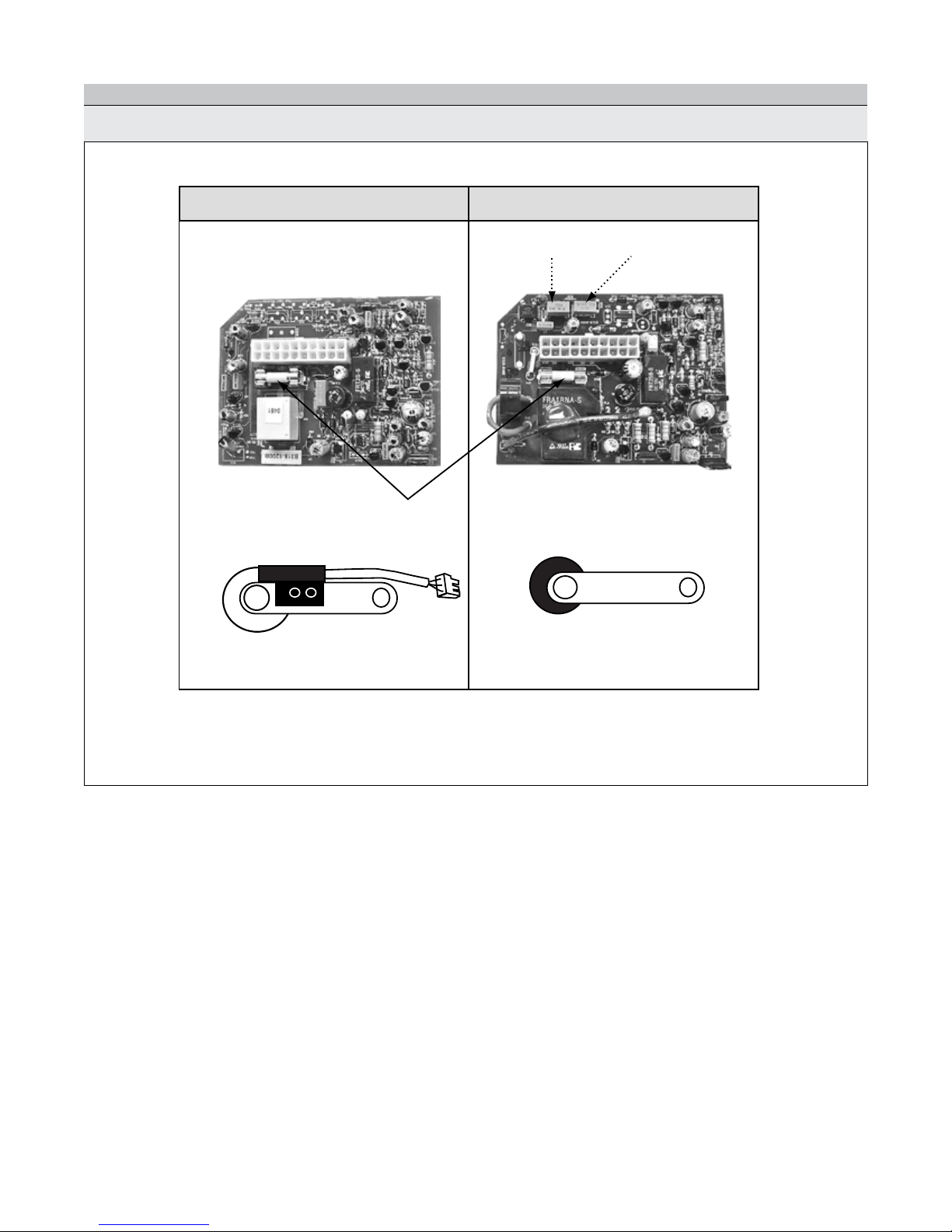
Belt Idler Assembly Belt Idler Assembly
PC Board PC Board
.5 and .6 .4 and older
Brush Roll AFI
Fuse
C. General Issues - continued
C.3. Identifying Models by PCB Layout or Belt Idler Assembly
Figure B. PCB Layout and Belt Idler Assembly
NOTE: The PC Boards in the .5 and .6 do not have adjustment pods because they have a hall sensor on the belt idler assembly.
071807 I. Common Issues
5
Page 8
II. Maintenance Procedures
1
2
3
4
5
A. Disassembly Instructions
A. Step 1.
1. Remove the handle and dust cover.
2. Place the vacuum face down on the bench.
3. Remove the base plate by removing the 2 (two) screws.
4. Remove the agitator/brushroll.
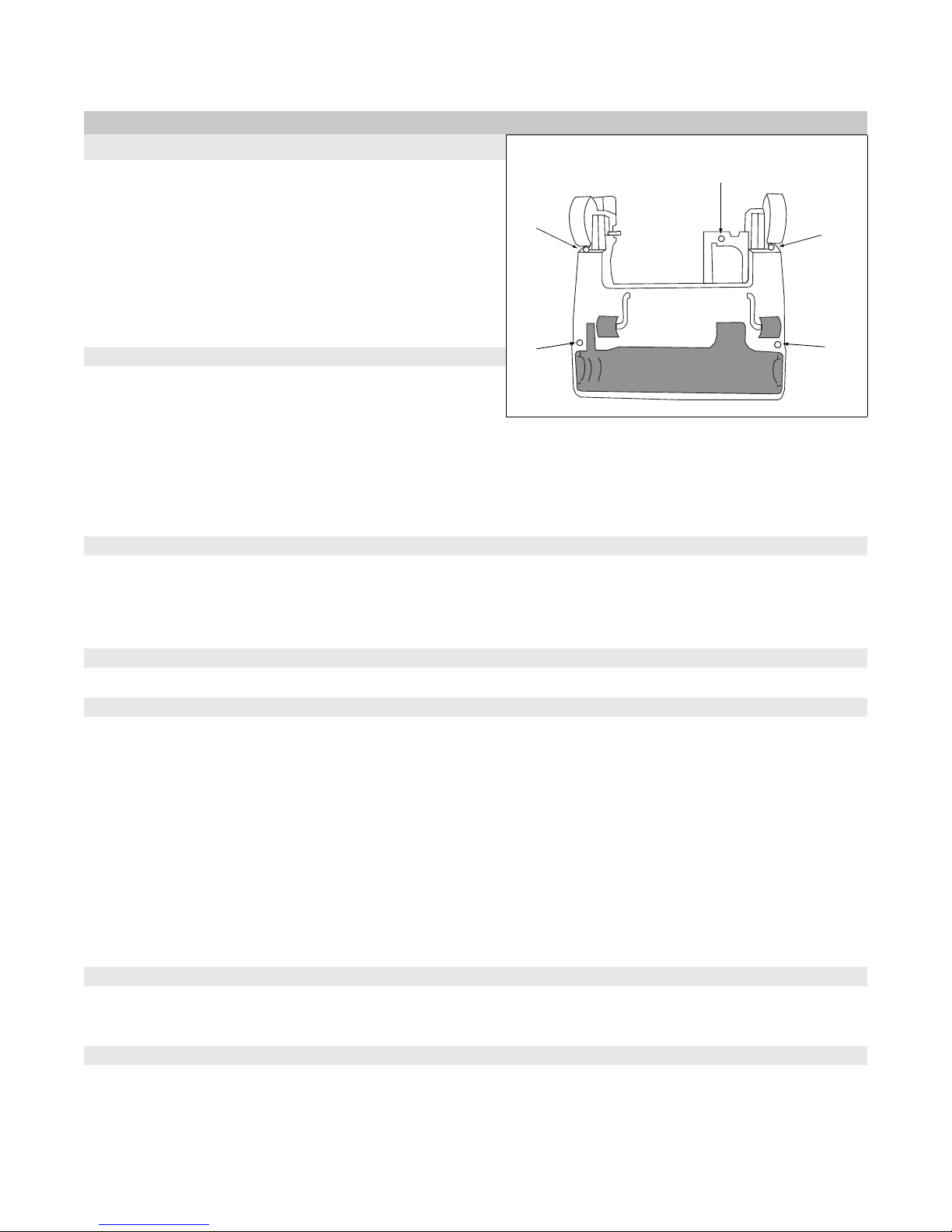
5. Remove the 5 (ve) mounting screws on the underside of the
nozzle base tray. (See Figure C. Location of Nozzle Cover
Screws)
A. Step 2. Removing the Back Path and Cover
1. Remove 1 (one) screw in the tools activation dial/rotational
valve handle and 8 (eight) screws on the back path and hose.
2. Remove tools activation dial/rotational valve handle and back path cover.
3. Remove 1 (one) screw from the micro switch and then the remaining 13 (thirteen) screws in the back cover.
4. Remove the back cover allowing the micro switch to slide through the slot in cover.
5. Remove the tool clips.
A. Step 3.
NOTE: Skip to A. Step 4. if wiring harness is NOT being changed.
Figure C. Location of Nozzle Cover Screws
A. Step 4.
A. Step 5.
A. Step 6.
1. If wire inlet seal (foam seal where the wire goes through the dust compartment) is installed, remove it at this time.
2. Remove the wire harness connector from the dust compartment and the micro switch from the wiring harness.
Turn the vacuum over, depress handle release, and lay at. Remove the nozzle cover.
WARNING - If the vacuum is not in the upright position before continuing with the next step, injury may occur or vacuum
may be damaged.
1. Set the vacuum in the upright position and remove the 2 (two) screws from the spring assist bar.
2. Lay the vacuum at. Remove the 3 (three) screws from the direct air motor inlet duct cover, and 1 (one) screw from each of
the wire strain relief (2 each) .
3. Remove the belt.
4. Remove 3 (three) screws from the idler cover and spring.
5. Disconnect the light lead connector from the light board (disconnect the ground wire if necessary).
6. Remove the 2 (two) screws from each of the pivot brackets.
1. Lift the dust compartment up out of the nozzle base tray assembly.
2. Remove the pivot bushings and the direct air motor inlet seal from the dust compartment.
A. Step 7.
1. Remove the 4 (four) screws holding the motor cover on the dust compartment.
2. Lift up on the motor cover and set it aside. -continue on next page
071807 II. Maintenance Procedures
5
Page 9

A. Disassembly Instructions - Continued
A. Step 8.
1. .4 models and older - Remove the direct air motor by lifting up and rotating, and then disconnect the leads.
2. .5 models and newer - Remove screw holding direct air motor in place and lift up.
A. Step 9.
Remove the clean air motor motor and disconnect the leads.
A. Step 10.
NOTE: Complete A. Step 10 and A. Step 11 only if wiring harness is being changed.
1. Remove the screw from the PC board.
2. Disconnect the wiring harness and remove the PC board.
3. Remove the screw in the metal plate and the metal plate from the dust compartment.
A. Step 11.
1. Remove the 2 (two) screws that hold the thermal reset switch in place.
2. Remove the winged rocker switch from dust compartment and disconnect the leads.
3. Slide the wire harness through the hole in the back of the dust compartment
4. Raise the corner of the main body seal and remove the wiring harness.
071807 II. Maintenance Procedures
6
Page 10
B. Removing the Brush Strips
1
1
2
2
3
3
4
5
5
5
B. Step 1.
1. Remove the base plate by removing the 2 (two) screws.
2. Remove the agitator/brushroll.
3. If the belt un-loops itself from the motor shaft, the nozzle cover may need to be removed by removing the 5 (ve) mounting
screws on the underside of the nozzle base tray. (See Figure C. Location of Nozzle Cover Screws.)
B. Step 2.
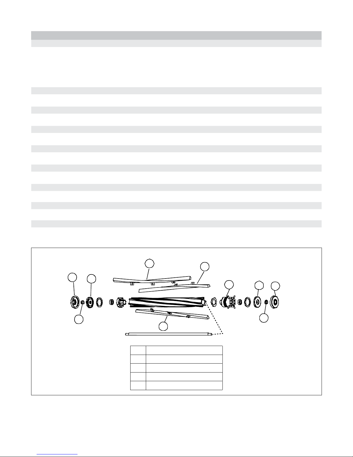
Remove the rubber end cap covers. Figure D. Agitator/Brushroll Assembly
B. Step 3.
Remove the nuts on each end of the agitator/brushroll with a 7/16 socket driver. Figure D. Agitator/Brushroll Assembly
B. Step 4.
Slide off the end caps. Figure D. Agitator/Brushroll Assembly
B. Step 5.
Pry off the belt pulley with a standard screwdriver. Figure D. Agitator/Brushroll Assembly
B. Step 6.
Slide off the brush strips and replace. Figure D. Agitator/Brushroll Assembly
B. Step 7.
Line up the belt pulley and push on.
B. Step 8.
Reinstall the steel end caps and nuts and tighten with a socket.
B. Step 9.
Reinstall the rubber end cap covers.
Figure D. Agitator/Brushroll Assembly
1 Agitator/brushroll End Cap Cover
2 1/4-28 Locking Hex Nut
3 Agitator/brushroll Steel End Cap
4 Agitator/brushroll Pully
5 Brush Strips
071807 II. Maintenance Procedures
7
Page 11
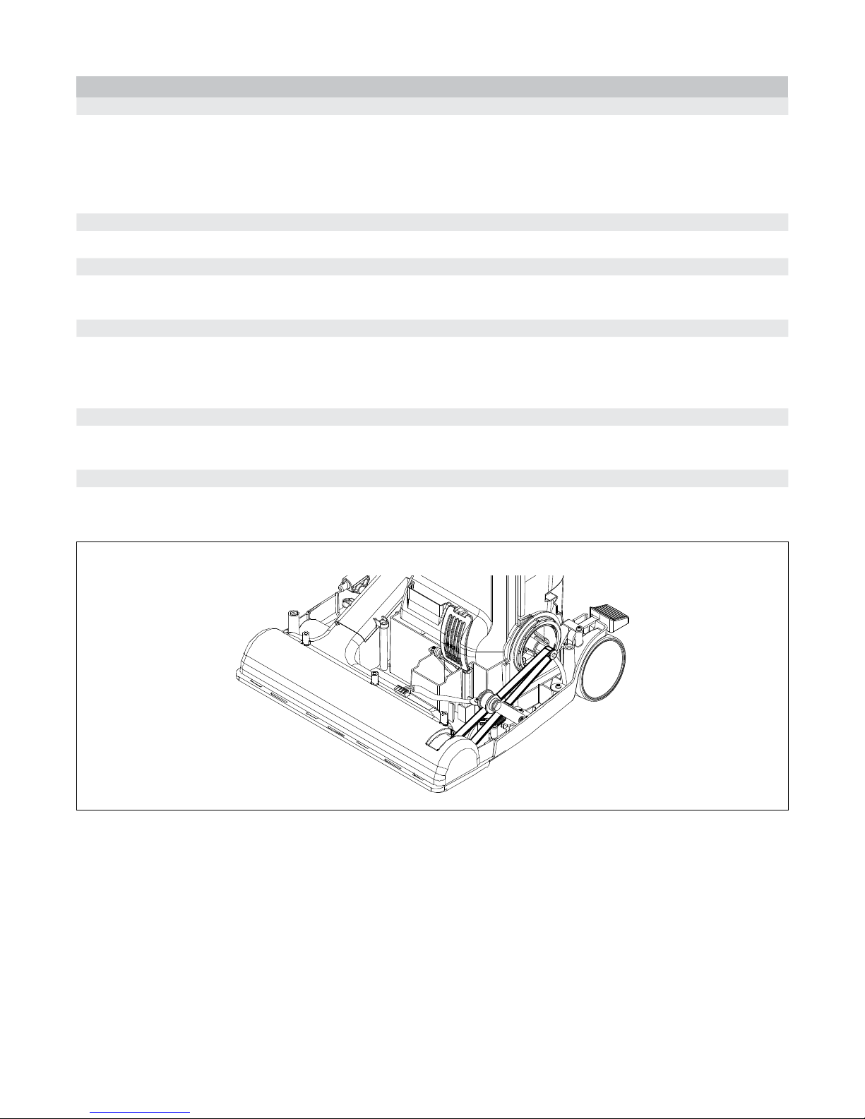
C. Replacing the Belt
C. Step 1.
1. Remove the base plate by removing the 2 (two) screws.
2. Remove the agitator/brushroll.
3. Remove the 5 (ve) mounting screws on the underside of the nozzle base tray. (See Figure C. Location of Nozzle Cover
Screws)
C. Step 2.
Discard the broken belt.
C. Step 3.
Note the layout of the idler assembly and the motor drive pulley. (See Figure E. Belt Placement) Loop the new belt over the
motor drive pulley then continue directing the belt under the idler pulley. Insert the belt into the nozzle base tray.
C. Step 4.
Turn the vacuum over and pull the belt into the nozzle base tray. Loop belt around the agitator/brushroll making sure the ribs
of the belt line up with the ribs on the agitator/brushroll.
NOTE: Ensure the felt seals are installed in the nozzle base tray.
C. Step 5.
Insert the agitator/brushroll into the nozzle base tray making sure the rubber end cap covers t precisely into the ribbed mounts
on the nozzle base tray. Rotate the agitator/brushroll a few times to ensure the belt is mounted correctly.
C. Step 6.
Reinstall the base plate and the nozzle cover.
NOTE: If the agitator/brushroll runs backwards, check the belt to ensure it is not twisted.
Figure E. Belt Placement
071807 II. Maintenance Procedures
8
Page 12

D. Replacing the LED Light Board
D. Step 1.
Remove the 5 (ve) mounting screws on the underside of the nozzle base tray. (See Figure C. Location of Nozzle Cover
Screws)
D. Step 2.
Remove the 3 (three) screws holding the light board onto the nozzle base tray - the middle screw may have the ground wire
attached.
D. Step 3.
Disconnect the wire connector and replace the light board.
D. Step 4.
Install the 3 (three) screws into LED light board attaching it to the nozzle base tray. NOTE: If the ground wires are on the wiring
harness or the LED light board, place the ground wires under middle screw.
D. Step 5.
Attach the wiring harness connector to the LED light board connector.
D. Step 6.
Reinstall the nozzle cover.
E. Replacing the Spring Assist Assembly
WARNING - If the vacuum is not in upright position injury may occur or vacuum may be damaged.
- Always wear safety glasses during repair.
E. Step 1.
Remove the 5 (ve) mounting screws on the underside of the nozzle base tray. (See Figure C. Location of Nozzle Cover
Screws)
E. Step 2.
With the vacuum locked in the upright position, remove the 2 (two) screws from the bracket holding the spring.
E. Step 3.
Ensure that the spring has been disconnected. Lay the vacuum at to remove the spring mount by pressing the ramped black
tab of the spring mount with a at screwdriver while pulling the spring out-ward.
E. Step 4.
Remove the bracket and mount from the old spring and attach to the new spring.
E. Step 5.
Push the spring mount into the motor cover until the mount snaps into place.
E. Step 6.
Lock the vacuum in the upright position.
E. Step 7.
Insert the two screws in to the spring bracket.
E. Step 8.
Reinstall the nozzle cover.
071807 II. Maintenance Procedures
9
Page 13

F. Replacing the Main PC Board
Note: Static electricity is a potential problem and could damage the PC board if a charge is transferred from yourself to the board
during handling and installation. Keep the board in the anti-static packaging until ready to install. It is best to use anti-static
protection such as a grounding wrist strap. Avoid performing this assembly on carpet or other areas which are prone to static
charge buildup.
Refer to Figure B. PCB Layout and Belt Idler Assembly, page 3.
F. Step 1.
1. Remove the handle and the dust cover.
2. Place the vacuum face down on the bench.
3. Remove the base plate by removing the 2 (two) screws.
4. Remove the agitator/brushroll.
5. Remove the 5 (ve) mounting screws on the underside of the nozzle base tray. (See Figure C. Location of Nozzle Cover
Screws)
F. Step 2.
Turn the vacuum over, depress handle release, and lay at. Remove the nozzle cover.
F. Step 3.
WARNING - If the vacuum is not in the upright position before continuing with the next step, injury may occur or vacuum
may be damaged.
1. Set the vacuum in the upright position and remove the 2 (two) screws from the spring assist bar.
F. Step 4.
F. Step 5.
F. Step 6.
F. Step 7.
F. Step 8.
2. Lay the vacuum at. Remove the 3 (three) screws from the direct air motor inlet duct cover, and 1 (one) screw from each of
the wire strain relief (2 each)
3. Remove the belt.
4. Remove the 3 (three) screws from the idler cover and spring.
5. Disconnect the light lead connector from the light board (disconnect the ground wire if necessary).
6. Remove the 2 (two) screws from each of the pivot brackets.
1. Lift the dust compartment up out of the nozzle base tray assembly.
2. Remove the pivot bushings and the direct air motor inlet seal from the dust compartment.
1. Remove the 4 (four) screws holding the motor cover on the dust compartment.
2. Lift up on the motor cover and set it aside.
Remove the screw connecting the PC board to the dust compartment.
Disconnect the wire harness connector and slide the PC board from the dust compartment.
Slide the board into the side channels and push board into place, then connect the wire harness to the new board.
F. Step 9.
Re-insert the single screw to secure the board and reattach the wire harness connector.
F. Step 10.
Re-assemble the vacuum by continuing to section II. Maintenance Procedures, H. Installing the Motor Cover.
071807 II. Maintenance Procedures
10
Page 14

G. Replacing the Clean Air Motor
White Wire
Black/White Wire
Blue Wire
White Wire
Yellow Wire
Black Wire
Side of
clean air motor
should line up
here in dust
compartment
G. Step 1.
1. Remove the handle and the dust cover.
2. Place the vacuum face down on the bench.
3. Remove the base plate by removing the 2 (two) screws.
4. Remove the agitator/brushroll.
5. Remove the 5 (ve) mounting screws on the underside of the nozzle base tray.
(See Figure C. Location of Nozzle Cover Screws)
G. Step 2.
Turn the vacuum over, depress handle release, and lay at. Remove the nozzle cover.
Figure F. Clean Air Motor Wiring
G. Step 3.
Figure G. Ametek Clean Air Motor Wiring
WARNING - If the vacuum is not in the upright position before continuing
with the next step, injury may occur or vacuum may be damaged.
1. Set the vacuum in the upright position and remove the 2 (two) screws from the
spring assist bar.
2. Lay the vacuum at. Remove the 3 (three) screws from the direct air motor inlet
duct cover, and 1 (one) screw from each of the wire strain relief (2 each).
3. Remove the belt.
4. Remove 3 (three) screws from the idler cover and spring.
5. Disconnect the light lead connector from the light board (disconnect the ground wire if necessary).
6. Remove the 2 (two) screws from each of the nozzle base tray pivot brackets.
G. Step 4. Figure H. Clean Air Motor Placement
1. Lift the dust compartment up out of the nozzle base tray assembly.
2. Remove the pivot bushings and the direct air motor inlet seal from the dust
compartment.
G. Step 5.
1. Remove the 4 (four) screws holding the motor cover on the dust compartment.
2. Lift up on the motor cover and set it aside.
G. Step 6.
To remove the clean air motor, grasp and lift it (located in the upper motor compartment) from the mount.
G. Step 7.
Note the orientation of the motor mount on the bracket end of the motor. The motor must be installed in the same manner with
the at edge of the rubber mount against the at walled structure on the dust compartment.
G. Step 8.
Attach the wires to the new motor as shown in Figure F. Clean Air Motor Wiring or Figure G. Ametek Clean Air Motor Wiring.
In the old style motor (Figure F. Clean Air Motor Wiring), notice that the blue wire should again be attached to the base of
the white wire connection with a zip tie.
G. Step 9.
G. Step 10.
071807 II. Maintenance Procedures
Insert the motor into the motor compartment. (See Figure H. Clean Air Motor Placement)
Re-assemble the vacuum by continuing to section II. Maintenance Procedures, H. Installing the Motor Cover.
11
Page 15

H. Installing the Motor Cover
Note the proper location of the two cables passing from the clean air motor compartment to the direct air motor compartment.
They should be stored in the channel of the rib wall before the motor cover is reinstalled. If not, the rib wall could pinch and
damage the cables. The cables may also prevent the motor cover from seating properly into place. Make sure all gaskets are
also seated properly.
H. Step 1.
Set the motor cover into place and secure with 4 (four) screws.
H. Step 2.
Attach the 2 (two) inner pivot brackets. Note that each bracket locks into place to be properly seated.
H. Step 3.
Attach the inlet seal to the inlet of the direct air motor.
H. Step 4.
Attach the two outer pivot brackets.
H. Step 5.
Slide the outer pivot brackets into the channels of the base compartment.
H. Step 6.
Secure each outer pivot bracket with 2 (two) screws on each bracket.
H. Step 7.
Attach the inlet duct cover with 3 (three) screws.
H. Step 8.
Note the layout of the idler assembly and the motor drive pulley. (See Figure E. Belt Placement) Loop the new belt over the
motor drive pulley then continue directing the belt under the idler pulley. Insert the belt into the nozzle base tray.
H. Step 9.
Turn the vacuum over and pull the belt into the nozzle base tray. Loop the belt around the agitator/brushroll making sure the
ribs of the belt line up with the ribs on the agitator/brushroll.
NOTE: Ensure the felt seals are installed in the nozzle base tray.
H. Step 10.
Insert the agitator/brushroll into the nozzle base tray making sure the rubber end cap covers t precisely into the ribbed mounts
on the nozzle base tray. Rotate the agitator/brushroll a few times to ensure the belt is mounted correctly.
H. Step 11. Reinstall the spring assist:
1. Push the spring mount into the motor cover until the mount snaps into place.
2. Lock the vacuum in the upright position.
3. Insert the two screws in to the spring bracket.
H. Step 12.
Reinstall the base plate and the nozzle cover.
H. Step 13.
Reinstall the dust cover.
071807 II. Maintenance Procedures
12
Page 16

I. Removing and Replacing the Direct Air Motor
I. Step 1.
1. Remove the handle and the dust cover.
2. Place the vacuum face down on the bench.
3. Remove the base plate by removing the 2 (two) screws.
4. Remove the agitator/brushroll.
5. Remove the 5 (ve) mounting screws on the underside of the nozzle base tray. (See Figure C. Location of Nozzle Cover
Screws)
I. Step 2. Removing the Back Path and Cover
1. Remove 1 (one) screw in the tools activation dial/rotational valve handle and 8 (eight) screws on the back path and hose.
2. Remove the tools activation dial/rotational valve handle and the back path cover.
3. Remove 1 (one) screw from the micro switch and then the remaining 13 (thirteen) screws in the back cover.
4. Remove the back cover allowing the micro switch to slide through the slot in cover.
5. Remove the tool clips.
I. Step 3.
NOTE: If wiring harness does not need to be changed, Skip to I. Step 6.
1. If wire inlet seal (foam seal where the wire goes through the dust compartment) is installed, remove it at this time.
I. Step 4.
I. Step 5.
I. Step 6.
I. Step 7.
2. Remove the wire harness connector from the dust compartment and the micro switch from the wiring harness.
Turn the vacuum over, depress the handle release, and lay the vacuum at. Remove the nozzle cover.
WARNING - If the vacuum is not in the upright position before continuing with the next step, injury may occur or
vacuum may be damaged.
1. Set the vacuum in the upright position and remove the 2 (two) screws from the spring assist bar.
2. Lay the vacuum at. Remove the 3 (three) screws from the direct air motor inlet duct cover, and 1 (one) screw from each
of the wire strain relief (2 each)
3. Remove the belt.
4. Remove 3 (three) screws from the idler cover and spring.
5. Disconnect the light lead connector from the light board (disconnect the ground wire if necessary).
6. Remove the 2 (two) screws from each of the pivot brackets.
1. Lift the dust compartment up out of the nozzle base tray assembly.
2. Remove the pivot bushings and the direct air motor inlet seal from the dust compartment.
1. Remove the 4 (four) screws holding the motor cover on the dust compartment.
2. Lift up on the motor cover and set it aside.
I. Step 8.
1. .4 models and older - Remove the direct air motor by lifting up and rotating, and then disconnect the leads.
2. .5 models and newer - Remove the screw holding the direct air motor in place and lift up. - continue on next page
071807 II. Maintenance Procedures
13
Page 17

I. Removing and Replacing the Direct Air Motor - Continued
I. Step 9.
The direct air motor is located in the lower motor compartment (nearest the nozzle).
To remove the direct air motor place a hand on each side of motor and lift up and rotate the motor toward the dust
compartment.
I. Step 10.
Disconnect the white and black motor leads.
I. Step 11.
To install the motor:
1. Ensure the rubber seal is installed on the dust compartment.
2. Ensure the motor seal by the shaft is in good condition.
3. Place the black wire under the motor and connect it. Connect the white wire, (hold the black wire as you place the motor
into the motor compartment to keep from pinching the wire).
4. Place the motor into the motor compartment, (do not push all the way down) shaft side rst then fan side, keeping the motor
level as it goes in.
5. Check the back of the vacuum to ensure the scroll housing is not catching on the rubber seal.
6. Rotate the motor as you push it down into the dust compartment. Once in place the metal motor support should rest in
between the bracket.
7. Raise up the shaft end of the motor, install the wire guide, and push the motor down into place.
Note the proper location of the two cables passing from the clean air motor compartment to the direct air motor
compartment. They should be stored in the channel of the rib wall before the motor cover is reinstalled. If not, the
rib wall could pinch and damage the cables. The cables may also prevent the motor cover from seating properly into
place. Make sure all gaskets are also seated properly.
071807 II. Maintenance Procedures
14
Page 18

J. Replacing the Direct Air Motor Fan
J. Step 1.
1. Remove the handle and the dust cover.
2. Place the vacuum face down on the bench.
3. Remove the base plate by removing the 2 (two) screws.
4. Remove the agitator/brushroll.
5. Remove the 5 (ve) mounting screws on the underside of the nozzle base tray. (See Figure C. Location of Nozzle Cover
Screws)
J. Step 2. Removing the Back Path and Cover
1. Remove 1 (one) screw in the tools activation dial/rotational valve handle and 8 (eight) screws on the back path and hose.
2. Remove the tools activation dial/rotational valve handle and the back path cover.
3. Remove 1 (one) screw from the micro switch and then the remaining 13 (thirteen) screws in the back cover.
4. Remove the back cover allowing the micro switch to slide through the slot in cover.
5. Remove the tool clips.
J. Step 3.
NOTE: If wiring harness does not need to be changed, Skip to I. Step 6.
1. If wire inlet seal (foam seal where the wire goes through the dust compartment) is installed, remove it at this time.
J. Step 4.
J. Step 5.
J. Step 6.
J. Step 7.
2. Remove the wire harness connector from the dust compartment and the micro switch from the wiring harness.
Turn the vacuum over, depress handle release, and lay at. Remove the nozzle cover.
WARNING - If the vacuum is not in the upright position before continuing with the next step, injury may occur or
vacuum may be damaged.
1. Set the vacuum in the upright position and remove the 2 (two) screws from the spring assist bar.
2. Lay the vacuum at. Remove the 3 (three) screws from the direct air motor inlet duct cover, and 1 (one) screw from each of
the wire strain relief (2 each)
3. Remove the belt.
4. Remove 3 (three) screws from the idler cover and spring.
5. Disconnect the light lead connector from the light board (disconnect the ground wire if necessary).
6. Remove the 2 (two) screws from each of the pivot brackets.
1. Lift the dust compartment up out of the nozzle base tray assembly.
2. Remove the pivot bushings and the direct air motor inlet seal from the dust compartment.
1. Remove the 4 (four) screws holding the motor cover on the dust compartment.
2. Lift up on the motor cover and set it aside.
J. Step 8.
Separate the scroll housing halves by removing the three e-clips and one screw.
J. Step 9.
Remove the nut from the motor fan by loosening it counter-clockwise then unscrewing the nut clockwise.
071807 II. Maintenance Procedures
15
Page 19

J. Replacing the Direct Air Motor Fan- Continued
J. Step 10.
1. Replace the fan.
2. Note the placement of the washer(s) on the fan. The placement of these washers is critical to allow the fan to tighten
properly on the motor shaft.
3. Tighten the nut counter-clockwise.
J. Step 11.
Reinstall the scroll housing with one screw and three e-clips.
J. Step 12.
To install the motor:
1. Insure the rubber seal is installed on the dust compartment.
2. Insure the motor seal by the shaft is in good condition.
3. Place the black wire under the motor and connect it. Connect the white wire, (hold the black wire as you place the motor into
the motor compartment to keep from pinching the wire).
4. Place the motor into the motor compartment, (do not push all the way down) shaft side rst then fan side, keeping the motor
level as it goes in.
5. Check the back of the vacuum to ensure the scroll housing is not catching on the rubber seal.
6. Rotate the motor as you push it down into the dust compartment. Once in place, the metal motor support should rest in
between the bracket.
7. Raise up the shaft end of the motor, install the wire guide, and push the motor down into place.
Note the proper location of the two cables passing from the clean air motor compartment to the direct air motor
compartment. They should be stored in the channel of the rib wall before the motor cover is reinstalled. If not, the
rib wall could pinch and damage the cables. The cables may also prevent the motor cover from seating properly into
place. Make sure all gaskets are also seated properly.
071807 II. Maintenance Procedures
16
Page 20

K. Replacing the Rear Wheels
NOTE: When replacing the wheels or hubcaps for .4 and older models, the entire wheel/axle set needs to be replaced.
K. Step 1.
Remove the rear wheel hubcaps by depressing the 3 lock tabs on the inside of the wheel.
K. Step 2.
Remove the e-clip on the outside of the wheel hub. Slide the rear wheel from the shaft, and replace with new wheel.
L. Replacing the Tilt Lock Pedal Spring
L. Step 1.
1. Remove the handle and the dust cover.
2. Place the vacuum face down on the bench.
3. Remove the base plate by removing the 2 (two) screws.
4. Remove the agitator/brushroll.
5. Remove the 5 (ve) mounting screws on the underside of the nozzle base tray. (See Figure C. Location of Nozzle Cover
Screws)
L. Step 2.
L. Step 3.
L. Step 4.
L. Step 5.
L. Step 6.
L. Step 7.
L. Step 8.
1. Remove the rear wheel hubcaps by depressing the 3 lock tabs on the inside of the wheel.
2. Remove the e-clip on the outside of the wheel hub. Slide the rear wheel from the shaft.
1. Remove the e-clip holding the tilt lock pivot shaft to the nozzle base tray (this e-clip is located in front of the rear wheel
axle).
2. Remove the tilt lock shaft by sliding it back through the hole.
Remove the tilt lock pedal by lifting it out from the top from the inside of the nozzle base tray.
Remove the tilt lock spring by lifting it out from the interior of the nozzle base tray.
Replace the tilt lock spring by tting it into its proper mounting structure. Note that the 1/4” long tab on this spring points
downward and sits ush with the backside of the nozzle base tray.
1. Insert the tilt lock pedal and slide the tilt lock pivot through the hole in the nozzle base tray and through the hole in the tilt lock
pedal.
2. Re-attach the e-clip to the pivot.
1. Reinstall the rear wheel and secure with e-clip.
2. Reinstall the hubcap.
L. Step 9.
Reinstall the nozzle housing (5 screws).
071807 II. Maintenance Procedures
17
Page 21

A. Vacuum has no power.
12
3
4
5
6
A. Step 1.
1. If there are lights in the handle switches there is power to the handle, continue to Step 2.
2. If there are no lights in the handle switches, there is no power to the vacuum or the power cord is faulty.
a. Check the power source.
b. Replace the power cord if damaged or faulty.
c. Retest the vacuum.
NOTE: Vacuum may not run even though the lights in the handle are “on”. If the handle is plugged in and turned “ON”,
the handle switch light will turn on even when the handle isn’t installed in the vacuum.
A. Step 2.
Handle switches are lit but neither motor will run.
1. Ensure the handle is installed correctly. (See Figure A. Correct Handle Installation)
2. Push the reset on the back of the vacuum and retest (See Figure T. Description of Vacuum)
3. If the vacuum still does not run continue to Step 3.
A. Step 3.
1. Unplug the vacuum.
III. General Troubleshooting
A. Step 4.
2. Remove the handle. Check the connector ends for any burnt pins.
3. If the connector ends are in good condition continue to Step 4.
4. If faulty connectors are found, replace the wiring harness.
5. Reassemble the vacuum and retest.
1. Plug the power cord in and turn the switches on.
2. Plug a test meter or light into the handle connector at the bottom of the handle, (one lead into the square connector on the
upper right (See Figure I. Handle to Body Harness Connector #4) and the other into the square connector on the lower left (See
Figure I. Handle to Body Harness Connector #3).
3. If the handle has power, continue to Step 5.
4. If the handle does NOT have power:
a) Unplug vacuum and disassemble handle.
b) Check all connections in handle.
c) If all the connections in the handle are good, change the wiring harness or install a new handle.
d) If all the connections in the handle are NOT good, replace any faulty connections.
e) Reassemble and retest vacuum.
Figure I. Handle to Body Harness Connector
#1 - Only square on connector. This is main power connector (Black Wire) connects to blue/yellow
body harness.
#4 - Connector for direct air motor via roto valve micro switch to winged rocker switch to PCB.
#6 & #3 - Grounds.
#5 & #2 - Not used
071807 III. General Troubleshooting
18
Page 22

A. Vacuum has no power. - Continued
A. Step 5.
1. Disassemble the vacuum and disconnect the PC board.
2. Using a test light or meter, test connector 10 (thermal lead) and either 5 or 6 (ground) on the main connector on the wire
harness. (See IV. Figures, P. Main Body Harness .5 and .6 Models or IV. Figures, S. Main Body Wire Harness .4 and Older
Models)
3. If the vacuum does NOT have power continue to Step 6.
4. If there is power to the PC board (thermal switch is good):
a) Check the fuse on the PC board. (See Figure B. PCB Layout and Belt Idler Assembly)
b) If the fuse is faulty, replace the fuse.
c) If the fuse is good, replace the PC board.
d) Retest the vacuum.
e) If the vacuum still does not run skip to Step 7.
A. Step 6.
1. Remove the clean air motor.
2. Disconnect the blue/yellow lead that connects to the thermal switch.
3. Place a meter or test light to the blue/yellow lead and the ground lead on the PC board connector.
A. Step 7.
4. With the vacuum plugged in and power switch “ON”, check for current ow.
5. If the vacuum has power at this point continue to Step 7.
6. If the vacuum does NOT have power call Tacony Technical Support at 1-800-643-7459
1. Connect the clean air motor to 110/120 volts (Use jumper wires and straight wire the motor).
2. If the motor does NOT run, reassemble the vacuum with a new motor and retest.
3. If the motor does run:
a) Check the fuse on the PC board. (See Figure B. PCB Layout and Belt Idler Assembly)
b) If the fuse is faulty, replace the fuse.
c) If the fuse is good, replace the PC board.
d) Retest the vacuum.
NOTE: If vacuum still will not run call Tacony Technical Service at 1-800-643-7459.
071807 III. General Troubleshooting
19
Page 23

B. Direct Air Motor Will Not Run
1. If nozzle cover is installed, the vacuum must be out of the upright position before the direct air motor will run.
2. If the nozzle cover is not installed, the direct air motor should run in the upright position.
3. .5 and newer models: If the belt is not installed, or the hall sensor is defective, the vacuum may run 2 to 3 seconds and then
cut off.
4. The handle should be attached to the vacuum and plugged into wall outlet. (See Figure A. Correct Handle Installation)
Check for headlights:
1. Direct air motor will not run. Clean air motor runs.
2. Turn the main power switch “ON”, (green light in switch on) and the oor/carpet switch to the carpet position with green light
on. Note: these lights will be on any time the handle is plugged into the outlet and switches are turned “ON”.
• No headlights: See Section B. 1. No Headlights.
• Headlights are on: See Section B. 2. Working Headlights
B.1. Direct Air Motor Will Not Run: No Headlights
B.1. Step 1.
1. Remove the dust cover then lay the vacuum face down.
2. Remove the nozzle cover (5 screws).
3. Place vacuum in the upright position and remove the 2 (two) screws from the assist spring.
4. Lay the vacuum at and remove the direct air motor inlet cover - 3 (three) screws in the inlet cover.
5. Remove the 2 (two) screws on each side of the dust compartment in brackets.
6. Remove the motor cover (4 (four) screws).
B.1. Step 2.
Check the clean air motor tap wire voltage:
1. Place one lead from a multi-meter on the white motor wire connection, and one lead on the blue or yellow tap wire
connection. (See Figure F. Clean Air Motor Wiring or Figure G. Ametek Clean Air Motor Wiring)
2. Turn the vacuum “ON” with the main power switch. With clean air motor running, read the voltage on the meter.
3. If reading is 12 to 18 AC volts the clean air motor is good.
4. If voltage is less than 12 volts replace the clean air motor.
5. If voltage is 18 or more, check fuse on the PCB:
a) If fuse is faulty replace fuse and retest vacuum.
b) If fuse is good replace the PCB and retest the vacuum.
If vacuum still does not work properly continue through Section B.2. Direct Air Motor Will Not Run: Headlights are on:
071807 III. General Troubleshooting
20
Page 24

B.2. Direct Air Motor Will Not Run: Headlights are on
TANDEM
A I R
SYSTEM
Main Body
Nozzle (shown without cover)
Winged Rocker Switch
T
O
O
L
S
O
N
T
O
O
L
S
O
F
F
A
B
To jump micro switch,
remove wires from
connectors A and B
and join them together.
Figure is shown
without Air Hose Path
Cover which normally
covers this switch.
B.2. Step 1.
1. Check the position of tools activation dial/rotational valve handle. Tool dial must be in “OFF” position. Rotate the tool dial
fully counter clockwise and then back to full clockwise or “OFF” position.
2. If the vacuum runs reassemble and retest.
3. If the vacuum does NOT run, continue to B.2. Step 2.
B.2. Step 2.
1. Check the winged rocker switch to ensure it is not broken or
sticking and that the wing is extended and facing down.
2. Replace the switch if necessary and retest.
3. If the vacuum runs reassemble and retest.
4. If the vacuum does NOT run, continue to B.2. Step 3.
B.2. Step 3.
1. Looking at the back of the vacuum at the 3 o’clock position
of the tools activation dial/rotational valve handle, a spring is
visible which is part of the micro switch for the direct air motor.
With a small screw driver press the spring to the right to ensure
the micro switch is activated.
2. The tools dial and upper portion of the back path may be
removed to gain access to the micro switch.
Figure J. Location of Winged Rocker Switch
3. Turn the vacuum on and press the micro switch.
Figure K. Location of Micro Switch
4. If the direct air motor starts, reassemble and retest.
5. If the direct air motor does not start continue to B.2. Step 4.
B.2. Step 4.
1. Bypass or jump the micro switch. (See Figure K. Location of
Micro Switch)
2. If the vacuum starts, replace the micro switch and then
reassemble the vacuum and retest.
3. If the vacuum does NOT start, continue to B.2. Step 5.
B. Step 5.
1. Remove the dust cover and then lay vacuum face down.
2. Remove the nozzle cover (5 screws).
3. Place the vacuum in the upright position and remove the 2 (two) screws from the assist spring.
4. Lay the vacuum at and remove the direct air motor inlet cover - 3 (three) screws in the inlet cover.
5. Remove the 2 (two) screws on each side of the dust compartment in brackets.
6. Remove the motor cover (4 (four) screws).
B.2. Step 6.
1. Check the wiring on the winged rocker switch for broken wires.
2. If all the wiring is good, continue to B.2. Step 9.
3. If any wiring is faulty, replace wiring or switch and retest.
071807 III. General Troubleshooting
21
Page 25

Line up notch with
screw at 11 O’clock
position before
attaching Tools
“ON”/”OFF” Dial
B. Direct Air Motor Will Not Run - continued
B.2. Step 7.
If all switches appear to be good:
1. Check the brown wire on the wing rocker switch as follows. Place one lead of the multi-meter on the brown wire from the
micro switch. Place the other lead on the white/green wire at the PCB connector (#6) you should read 120 volts with main
power switch “ON” and oor/carpet switch in carpet position and Tool activation dial/rotational valve handle in the tools “OFF”
position.
2. If the voltage is low, go to the rotational valve micro switch and disconnect the brown wire from the handle connector and
the black micro switch wire turn the main power switch “ON” and place the carpet/oor switch to carpet. Place one lead from
the multi-meter to the brown wire from the handle and the ground wire to the number 5 or 6 PCB connector, voltage should
read around 120 volts.
3. If the voltage is within normal limits, the micro switch is faulty.
4. If voltage is low then the problem is in the handle connector or the handle wiring.
B.2. Step 8.
1. Unplug the direct air motor and hook it up directly to 110 volts.
2. If the motor runs continue to B.2. Step 9.
3. If the direct air motor does NOT run replace it and reassemble the vacuum and retest.
B.2. Step 9.
1. Check the wiring to the direct air motor and the PC board.
2. If all the wiring is good (not pinched and all connectors good) replace the PC board and retest.
3. If any wiring or connectors are faulty, replace them and retest.
4. Continue to B.2. Step 10.
B.2. Step 10.
1. If the motor runs reassemble the vacuum.
2. If the motor does NOT run replace the wiring harness; reassemble and retest.
NOTE: If vacuum still will not run call Tacony Technical Service at 1-800-643-7459.
Figure L. Proper Position for Tools Activation Dial/Rotational Valve Handle
071807 III. General Troubleshooting
22
Page 26

C. Nozzle Suction Power is Weak
1. Bag may be full or contain ne particles such as drywall dust or talc.
2. Filters may be dirty and need replaced.
C.1. There is no suction at the hose
C.1. Step 1.
The tool activation dial/rotational valve handle should be in the tools “ON” position.
C.1. Step 2.
Remove the hose and check for a clog in the hose. (If clogged remove the clog).
NOTE: If hose is clogged there will be suction at the hose inlet on the back path of the vacuum.
C.1. Step 3.
If there is no suction at the hose inlet at the back path:
1. Remove the tool activation dial/rotational valve handle.
2. Remove the 7 (seven) screws holding on the air hose path and hose inlet connector.
3. If clogged remove clog and re-assemble.
C.2. There is no suction at the nozzle
C.2. Step 1.
The tool activation dial/rotational valve handle should be in the tools “OFF” position.
C.2. Step 2.
C.2. Step 3.
C.2. Step 4.
C.2. Step 5.
C.2. Step 6.
Check the nozzle tray and agitator/brush roll for clog, clean agitator/brush roll as required.
Remove the dust cover and turn the vacuum “ON”, in carpet mode. The bag should inate assuring the air path is open and
the direct air motor is working.
If suction is still weak:
1. Remove the agitator/brush roll, nozzle cover, and direct air motor inlet cover.
2. Check for clogs in the inlet duct and direct air motor inlet, if clogged remove the clog and test again.
Models .5+ and newer, if suction is still weak:
Turn vacuum over and remove the clean out door and check and remove any clogs.
NOTE: You may turn the vacuum on and check the suction at the clean out door. This is done with the dust cover
installed, and with the upper motor only, if you have suction the air path is open and the clog is in the direct air
motor.
Models .5 and older, if suctions is still weak:
Remove the back cover to check the air path. If the air path is clear, the clog is in the direct air motor.
If clog is in the direct air motor remove the direct air motor (See II. Maintenance Procedures, I. Removing and Replacing the
Direct Air Motor) and the remove the outer scroll housing and check for any clog.
C.2. Step 7.
Re-assemble the vacuum and retest.
071807 III. General Troubleshooting
23
Page 27

D. Excessive Vibration
1. Check the direct air fan for damage. Replace if necessary. (See II. Maintenance Procedures, J. Replacing the Direct Air Motor Fan)
2. The agitator/brushroll may be out of balance.
3. To test the agitator/brushroll for balance:
Models .4 and older:
1. Remove the agitator/brushroll and run the direct air motor.
2. If vibration stops with the agitator/brushroll removed, replace the agitator/brushroll and retest.
Models .5 and newer:
1. Remove the nozzle cover and install the hall sensor test plug. (If test plug is not installed, the direct air motor will only run 2 to
3 seconds and then shut off.)
2. Remove the agitator/brushroll and run the direct air motor.
3. If vibration stops with the agitator/brushroll removed, replace the agitator/brushroll and retest.
E. Agitator/brushroll Does Not Rotate
1. Check the condition of the belt. Replace if necessary.
2. Check the agitator/brushroll for excessive hair build-up. Clean agitator/brushroll if necessary.
Also see III. General Troubleshooting, B. Direct Air Motor Will Not Run
071807 III. General Troubleshooting
24
Page 28

F. Agitator/brushroll Jam Test
F. Step 1.
1. Turn the vacuum on. Turn the carpet/oor switch to carpet. Run the vacuum over a sock or towel to jam the agitator/
brushroll.
NOTE: Be sure to use thick enough sock or towel material so it doesn’t wrap around the agitator/brushroll.
2. The agitator/brushroll should stop completely, the direct air motor should turn off immediately, and the red indicator light
should turn on. (The clean air motor should continue to run).
3. If all conditions are met continue to F. Step 2.
4. If jam test fails remove the sock, and start the test again.
5. If test fails a second time, troubleshoot the source as either the PC Board or the Hall Sensor Assembly, and make the
appropriate repairs. Then test again.
F. Step 2.
Turn the Carpet/Floor switch to “Floor”.
F. Step 3.
Turn Carpet/Floor switch to “Carpet”.
Does the agitator/brushroll come on?
NO: Repeat F. Step 3.
YES: Replace PC Board, and test again.
F. Step 4.
F. Step 5.
F. Step 6.
Turn On/Off switch to “Off’.
Remove sock/towel.
Turn On/Off switch to “On” again.
If the red indicator light does not come back on the jam function is working properly.
If the red indicator light stays lit, replace the PC board and repeat the test.
071807 III. General Troubleshooting
25
Page 29

Plugs Covering
Screws
Motor Cover
Airflow Screw
Correct Position
(Ten O’Clock)
Brushroll
Jam Screw
Correct Position
(Eleven O’Clock)
IV. Trouble Shooting - .4 and Older Models Only
A. Full Bag Indicator (FBI) Comes On Too Soon or Not At All
If the light comes on too soon, the bag may be full or contain ne particles such as drywall dust or talc.
If the light does not come on at all, the bag may be full of uffy material.
If replacing the bag does not solve these problems, the sensor may need to be adjusted as follows:
Testing the Full Bag Indicator:
1. Run the vacuum for ve minutes to warm it up. Make sure the bag is new and the lters are clean.
2. With the wand kept in the stowed position, turn the tools activation dial/rotational valve handle to the “Tools ON” position.
3. The full bag indicator should illuminate within 18-23 seconds after turning the dial to the “Tools ON” position.
4. If the indicator comes on sooner or slower than 18-23 seconds (or not at all), the sensitivity may need to be adjusted.
Adjusting the Full Bag Indicator:
1. Unplug the power cord, remove the dust cover, and lay the vacuum at.
2. Locate the two plugs on the right side of the motor cover. (See Figure M. Agitator/brushroll Jam Screw - FBI Screw Position)
3. Remove the left plug from the motor cover. A gray colored adjustment screw should be visible through the hole.
4. The slot of the screw should be in the “Ten o’clock” position. If not, adjust it to the “Ten o’clock” using a small at-headed screwdriver that
ts through the hole.
NOTE: Be careful not to apply pressure while making the adjustment.
5. Reassemble the vacuum and retest it to ensure it is operating properly.
6. If the problem still exists, or if the screw is already adjusted to “Ten o’clock”, make gradual adjustments (approximately “one hour” increments or less). Turn the adjustment screw counter-clockwise to make it less sensitive (LED turns yellow slower), and clockwise to make it
more sensitive (LED turns yellow faster). It is important to make small adjustments and test the vacuum after each adjustment.
7. Retest the vacuum after each adjustment using the above procedures until the FBI comes on within 18-23 seconds.
Figure M. Agitator/brushroll Jam Screw - FBI Screw Position
071807 IV. Trouble Shooting - .4 and Older Models Only
26
Page 30

B. Agitator/brushroll Jam Light Comes On Too Soon or Not At All
Plugs Covering
Screws
Motor Cover
Airflow Screw
Correct Position
(Ten O’Clock)
Brushroll
Jam Screw
Correct Position
(Eleven O’Clock)
If the sensor is coming on too soon, the customer may be vacuuming one extra plush carpet. Set the height adjustment to higher level and
retest. If the sensor still comes on too soon, it may be out of calibration and need adjusting. - See Adjusting the Agitator/brushroll Jam
Indicator below.
If sensor is coming on too late or not at all the sensor may be out of calibration and need adjustment. - See Adjusting the Agitator/brushroll
Jam Indicator below.
Adjusting the Agitator/brushroll Jam Indicator:
1. Unplug the power cord, remove the dust cover, and lower the upper body to the reclined position.
2. Locate the two plugs on the right side of the motor cover. (See Figure M. Agitator/brushroll Jam Screw - Full Bag Screw Position)
3. Remove the right plug from the motor cover. A gray colored airow adjustment screw should be visible through the hole.
4. The slot of the screw should be in the “Eleven o’clock” position. If not, adjust it to the “Eleven o’clock” position using a small at-headed
screwdriver that ts through the hole.
NOTE: Be careful not to apply pressure while making the adjustment.
5. Reassemble the vacuum and retest it to ensure it is operating properly. Follow testing procedure in Section III.Troubleshooting: G. Agitator/brushroll Jam Test
6. If the problem still exists, or if the screw is already adjusted to “Eleven o’clock”, make gradual adjustments (approximately “one hour”
increments or less). Turn the adjustment screw counter-clockwise to make it less sensitive (harder to jam) and clockwise to make it more
sensitive (easier to jam). It is important to make small adjustments and test the vacuum after each adjustment.
Figure M. Agitator/brushroll Jam Screw - FBI Screw Position
071807 IV. Trouble Shooting - .4 and Older Models Only
27
Page 31

V. Trouble Shooting - .5 and .6 Models Only
A. Direct Air Motor Starts But Shuts Off in 2 or 3 Seconds
NOTE: Any time the nozzle cover is removed the direct air motor will run with the vacuum in the upright position.
A. Step 1.
Remove the nozzle cover. (See Figure C. Location of Nozzle Screws)
Is the hall sensor lead connected to the wiring harness?
NO: Connect the hall sensor lead to the wiring harness.
YES: Go to A. Step 2.
A. Step 2.
Are both magnets installed on the pulley?
NO: Replace the hall sensor.
YES: Go to A. Step 3.
A. Step 3.
Is the belt installed? (For the direct air motor to run, the pulley on the belt idler must turn, this is where the hall sensor is
installed.
NO: Install belt. (See II. Maintenance Procedures: C. Replacing Belt)
YES: Go to A. Step 4.
A. Step 4.
If the direct air motor still will not run more than 2 to 3 seconds, disconnect the hall sensor lead and place the hall sensor test
plug into the wiring harness.
A. Step 5.
Try to run the direct air motor again. If it runs with the test plug, replace the hall sensor.
B. The Full Bag Indicator will ash On when the vacuum is shut Off.
This is showing the system is working. To test for correct operation:
a) Warm the vacuum up for 2 to 3 minutes.
b) Turn the tools activation dial/rotational valve handle to the “Tools ON” position.
c) Block the end of the hose with your hand.
d) Light should come on within 2 minutes.
071807 V. Trouble Shooting - .5 and .6 Models Only
28
Page 32

N. Handle Assembly
4
5
6
7
8
9
10
11
12
10
13
14
15
17
16
19
20
21
18
2
3
1
22
VI. Figures
Key Description Key Description
1 Handle Assembly 12 Lower Cord Hook
2 Screw 13 Handle Mount Screw
3 Handle Pin 14 Handle Tube Base Connector
4 E-Clip 15 Handle Tube
5 Power Cord 16 Handle to Body Harness
6 Upper Cord Hook Base 17 Metal Handle Retainer
7 Upper Cord Hook 18 Steel Rod Pin
8 Spring 19 Switch Carpet/Floor
9 Washer 20 Switch On/Off
10 Screw M4x40 21 Wire Connector Md.
11 Upper Cord Hook Assembly 22 Handle Assembly Complete
071807 VI. Figures
29
Page 33

O. Body Assembly
1
2
3
4
6
8
9
10
16
17
18
19
22
20
21
23
28
29
30
31
32
33
56
56
56
56
56
56
56
35
37
38
30
36
52
39
40
41
42
43
44
7
62
3a
3b
3c
57
56
34
5
13
14
56
56
15
11
12
60
59
58
53
54
55
46
45
48
56
47
49
56
51
61
56
50
24
27
25
26
071807 VI. Figures
1 Dust Cover Assembly
2 Printed Dust Cover
3 Dust Cover Latch Body Assembly
3a Dust Cover Latch Body
3b Dust Cover Latch
3c Latch Cover
4 Dust Cover Lever
5 HEPA Bag
6 Carrying Handle
7 Motor Cover Seal
8 Direct Air Filter Cover
9 Direct Air Motor Filter
10 Motor Cover
11 Internal Air Path
12 Secondary Filter
13 Secondary Filter Frame
14 Post Filter Mount
15 Post Filter Seal
16 Bag Mount
17 Bag Mount Seal
18 Clean Air Motor Mount Rear
19 Clean Air Motor
20 Clean Air Motor Mount Front
21 Clean Air Motor Assembly
22 Printed Circuit Control Board
Main PCB - Hall Sensor (X9.5/6)
23 Direct Air Motor Inlet Seal
24 Direct Air Motor Assembly
25 Direct Air Cleaning Fan
26 Fan Washer
27 Direct Air Motor Shroud Seal
28 Internal Wire Harness
29 Dust Cover Catch
30 Pivot Bushing - Casting
31 Primary Dust Compartment Seal
32 Winged Rocker Switch
33 Thermal Reset Switch
34 Thermal Switch Seal
35 Dust Compartment
36 Inner Wire Guide
37 Tilt Lock Body Plate
38 Dust Compartment Assembly
39 Pleated Post Filter Base
40 Post Filter
41 Pleated Post Filter Cover
42 Pleated Post Filter Base Assembly
HEPA Plus Post Filter Base Assembly
43 Motor Outlet Dust Compartment Seal
44 Motor Outlet Back Plate Seal
45 Hose Inlet Elbow
Hose Airpath Seal (Not Shown)
46 O-Ring Hose Inlet Elbow Seal
47 Hose Inlet Cuff
48 O-Ring Hose inlet Cuff Seal
49 Air Hose Path
50 Rotational Valve Handle
51 Roto Valve Switch
52 Crevice Tool
53 Back Cover
54 Crevice Tool Clip
55 Rotational Valve
56 Screw
57 Screw
58 Upholstery Tool Assembly
59 Dust Brush Attachment Assembly
60 Combo Tool Assembly
61 Screw
30
62 Adjustment Hole Plug f/Circuit Board
Page 34

P. Nozzle Assembly
40
29
28
27
1 Lens Right
2 Lens Left
3 Nozzle Bumper
4 Nozzle Cover Assembly
5 Nozzle Badge
6 Nozzle Cover Printed
7 Indicator Light Adjust Lens
8 Retaining Ring
9 Height Adjust Assembly
10 Screws
11 Rear Wheel Hub Cap
12 Nozzle Inlet Duct Cover
13 Large Overmolded Wheel Assembly
14 E-Clip
15 Axle-Rear Wheel
16 Reector/Headlight Assembly
17 Agitator/brushroll Assembly
18 External Retaining Ring
19 Small Overmolded Wheel Assembly
20 Height Adjust Axle
21 Height Adjust Axle Cover
22 Baseplate Assembly W/Seals
23 Nozzle base tray
24 Top Agitator/brushroll Seal (X9.3)
25 Idler Arm Cover
26 Idler Arm Spring
27 Grounding Screw
28 Washer
29 Idler Assembly - Hall Sensor
30 Tilt Lock Spring
31 Tilt Lock Pivot
32 E-Clip .250”
33 Tilt Lock Pedal Assembly
34 Belt
35 Strain Relief Washer
36 Pivot Bracket - Left
37 Pivot Bracket - Right
38 Spring Assist Axle Shaft
39 Spring Assist Spring
40 Spring Mount Assist
41 Bottom Agitator/brushroll Seal
42 E-Clip
071807 VI. Figures
31
Page 35

CARPET
FLOOR
ON
OFF
White
White
White
White
Red
Black
Black
Black
Handle
Harness
Power
Cord
Q. Handle Wiring
NOTE: Light “ON” in switches on handle only indicates
that there is power to the switches.
The lights will come on any time the power cord is
plugged into an outlet and the switch is turned “ON”
regardless of whether the handle is installed in the
vacuum.
071807 VI. Figures
32
Page 36

Manual Reset
Thermo Circuit
Breaker
Direct
Air
Motor
Valve
Micro
Switch
Winged
Rocker
Switch
LED Connector
Handle Connection
Yellow
White
Red
Black
Brown
Blue
Green/Yellow Stripe
Black
Red
Black/Red Stripe
Black
Red
Black
Black/Red Stripe
Short Lead
Long Lead
Main Circuit Board Connector
Jacketed
Wire
Yellow
Black
Red
Jacketed
Wire
Green
Ground
Hall
Sensor
Connector
11
13
2
12
3
10 9 6
15
18
19716
Top of Connector
1
13
To PCB
11 12 13 14 15 16 20191817
1 2 3 4 5 6 10987
5
M
Clean Air Motor
M
Fiber
Glass
Jacketed Wire
White
White
Black
Black
Black/White
Blue
Blue or
Yellow
White
Black
R. Main Body Wire Harness .5 and .6 Models
NOTE: The following are required for Direct Air
Motor operation:
1. Power to the vacuum.
2. Handle seated in vacuum and secure.
3. Tools activation dial/rotational valve handle
turned to Tools “OFF” (micro switch closed).
4. Winged rocker switch disengaged (nozzle
cover off vacuum or handle out of the upright
position).
5. Headlights “ON”. (Head lights “ON” means
the clean air motor is providing power through
the PC board to the lights.)
NOTE: Back of Connector is Numbered
071807 VI. Figures
33
Page 37

Manual Reset
Thermo Circuit
Breaker
Direct
Air
Motor
Valve
Micro
Switch
Winged
Rocker
Switch
LED Connector
Handle Connection
Yellow
White
Red
Black
Brown
Blue
Green/Yellow Stripe
Black
Red
Black/Red Stripe
Black
Red
Black
Black/Red Stripe
Short Lead
Long Lead
Jacketed
Wire
Main Circuit Board Connector
13
2
12
3
10 9 6
15
18
19716
Top of Connector
To PCB
11 12 13 14 15 16 20191817
1 2 3 4 5 6 10987
M
Clean Air Motor
M
Fiber
Glass
Jacketed Wire
White
White
Black
Black
Black/White
Blue
Blue or
Yellow
White
Black
5
S. Main Body Wire Harness .4 and Older Models
NOTE: The following are required for Direct Air
Motor operation:
1. Power to the vacuum.
2. Handle seated in vacuum and secure.
3. Tools activation dial/rotational valve handle
turned to Tools “OFF” (micro switch closed).
4. Winged rocker switch disengaged (nozzle
cover off vacuum or handle out of the upright
position).
5. Head lights “ON”. (Head lights “ON” means
the clean air motor is providing power through
the PC board to the lights.)
071807 VI. Figures
34
NOTE: Back of Connector is Numbered
Page 38

ComfortGrip" handle
Main on / off power switch
Carpet / hardwood floor switch
34' power cord
ReadyReach™ tools
Carrying handle
Bag compartment latch
(to replace vacuum bag)
Vacuum nozzle
Twin LED headlamps
Furniture guard
Brushroll jam indicator
Full bag / clog indicator
Exhaust
filter
cover
Quick release cord hook
Telescopic wand
5-to-1
stretch hose
Tool
activation
dial
Combination dusting /
upholstery brush
Crevice tool
Release pedal
Carpet height
adjustment dial
Thermal reset button
T. Description of Vacuum
071807 VI. Figures
35
 Loading...