

Page 1
Full Size Canister Service Manual
Simplicity Models S36 / S38
Power Nozzles SPB-200 / SPB-220 / SPB-224 / SPB-250
Page 2

Table of Contents
I. General Full Size Canister Issues ���������������������������������������������������������������������������������������������������������������������������������������������������2
A� Full Bag Indicator �������������������������������������������������������������������������������������������������������������������������������������������������������������������������������������2
1. General information ����������������������������������������������������������������������������������������������������������������������������������������������������������������������������2
2. The red light on the handle is blinking.������������������������������������������������������������������������������������������������������������������������������������������������2
3. The full bag indicator fails to activate when the bag is full ������������������������������������������������������������������������������������������������������������������2
B� Check Filter Light ������������������������������������������������������������������������������������������������������������������������������������������������������������������������������������3
1. General information ����������������������������������������������������������������������������������������������������������������������������������������������������������������������������3
2. The reset switch does not reset the check lter light. �������������������������������������������������������������������������������������������������������������������������3
C� Common Issues ���������������������������������������������������������������������������������������������������������������������������������������������������������������������������������������4
1. Canister power switch does not click when pedal is depressed. ��������������������������������������������������������������������������������������������������������4
2. What to check rst when canister will not power up. ��������������������������������������������������������������������������������������������������������������������������4
3. Interpreting blinking LED light on the main PC board. ������������������������������������������������������������������������������������������������������������������������4
4. Canister will not run without the hose connected. �����������������������������������������������������������������������������������������������������������������������������4
5. Canister cuts on and off at the customers house but runs in the store. ����������������������������������������������������������������������������������������������4
6. Canister cuts on and off when plugged into a power strip, but runs when plugged into the wall. �������������������������������������������������������4
II. Full Size Canister Troubleshooting Guide ���������������������������������������������������������������������������������������������������������������������������������5
A� Cover Dis-assembly Instructions �������������������������������������������������������������������������������������������������������������������������������������������������������������5
B� Canister Shuts Off or Will Not Power Up �������������������������������������������������������������������������������������������������������������������������������������������������6
C� Canister Power Switch Fails to Power Up Unit; Hose Works Normally ���������������������������������������������������������������������������������������������������8
D� Canister Runs - Power Nozzle Does Not Run �����������������������������������������������������������������������������������������������������������������������������������������9
E� Power Nozzle Cuts On and Off When Using - Troubleshooting Wand ��������������������������������������������������������������������������������������������������10
F� Power Nozzle w/ Dirt Sensor Will Not Run But Canister Runs ���������������������������������������������������������������������������������������������������������������11
G� Power Nozzle w/ Dirt Sensor Runs But Indicator Light Will Not Change ����������������������������������������������������������������������������������������������12
H� Wire Harness Upgrade Instructions �������������������������������������������������������������������������������������������������������������������������������������������������������13
III. Full Size Canister Figures
A� Main Parts Assembly �������������������������������������������������������������������������������������������������������������������������������������������������������������������������������5
B� Power Nozzle Reset Switch Location ����������������������������������������������������������������������������������������������������������������������������������������������������10
C� Power Nozzle Warning Light & Dirt Sensor Location ����������������������������������������������������������������������������������������������������������������������������11
D� HEPA Reset Button Location� ������������������������������������������������������������������������������������������������������������������������������������������������������������������3
E� Main Parts ����������������������������������������������������������������������������������������������������������������������������������������������������������������������������������������������14
F� Body Assembly ���������������������������������������������������������������������������������������������������������������������������������������������������������������������������������������15
G� Cover Assembly ������������������������������������������������������������������������������������������������������������������������������������������������������������������������������������16
H� Dust Cover Assembly ����������������������������������������������������������������������������������������������������������������������������������������������������������������������������17
J� Hose Assembly ���������������������������������������������������������������������������������������������������������������������������������������������������������������������������������������18
K� Wiring Diagram for Harness Upgrade ����������������������������������������������������������������������������������������������������������������������������������������������������19
L� Wiring Diagram For Dirt Sensor Models�������������������������������������������������������������������������������������������������������������������������������������������������20
M� Wiring Diagram For Non-Dirt Sensor Models ����������������������������������������������������������������������������������������������������������������������������������������20
Page 3

IMPORTANT SAFETY INSTRUCTIONS
When using or servicing any electrical appliance, basic precautions should always be
followed, including the following:
WARNING: To reduce the risk of re, electrical shock, or injury:
1. Do not leave canister unattended when plugged in. Unplug from outlet when not in use.
2. Turn off all controls before unplugging.
3. Do not attempt to service canister while plugged in.
4. Before handling PC board, discharge static electricity by using anti-static mat and
ground strap. If anti-static mat is not available, touch a metal object that is grounded and
only handle PC board by outside edges.
5. Disconnect from power source before removal of any panel or replacement of any
component.
WARNING: ELECTRIC SHOCK COULD OCCUR IF USED OUTDOORS OR ON WET SURFACES.
Page 4

I. General Full Size Canister Issues
A. Full Bag Indicator
1. General information
A pressure sensor, located on the main PC board, governs the “full bag indicator” feature� This sensor is connected to the bag cavity via
an air tube� When the pressure exceeds the actuation limit for a minimum time period of 20 seconds (+ or –10), the red light blinks on the
handle� If this condition goes unchecked the canister may over heat and shut down�
NOTE: Hose connects to white pressure sensor on PC board�
2. The red light on the handle is blinking.
1. Bag is sufciently full to restrict airow.
2. Hose, wand, or attachment may be clogged or attachment size is restricting airow.
3� Sensor or connecting tube may be clogged�
4. For ltering purposes HEPA bags have very small airow pores. Because these pores are so small, they are susceptible to clogging
when vacuuming very ne debris such as drywall dust or talcum powder. In these instances, the bag may not appear to be full.
5� If none of the above conditions exist, and the full bag indicator light on the handle is blinking, the sensor may be set improperly�
6. The hose or PC board may be bad. Remove the HEPA lter and see if the FBI light goes out. If the FBI light stays “ON” the hose is
should be replaced, otherwise the PC board needs to be replaced�
3. The full bag indicator fails to activate when the bag is full
1. The bag may be lled with uff. Light, low-density materials can ll the bag but still allow enough airow through so that the pressure
never reaches the sensor’s actuation limit�
2� There may be a problem with the wiring in the handle/hose assembly� Try a known good hose and re-test�
3� There may be a problem with the handle PC board�
4� The air tube may be dis-connected or damaged�
5� If none of the above conditions exist and the full bag indicator on the handle does not blink when the bag is full, the sensor may be set
improperly�
6. The hose or PC board may be bad. Remove the HEPA lter and see if the FBI light goes out. If the FBI light stays “ON” the hose is
should be replaced, otherwise the PC board needs to be replaced�
2
I� General Full Size Canister Issues07�03�07
Page 5
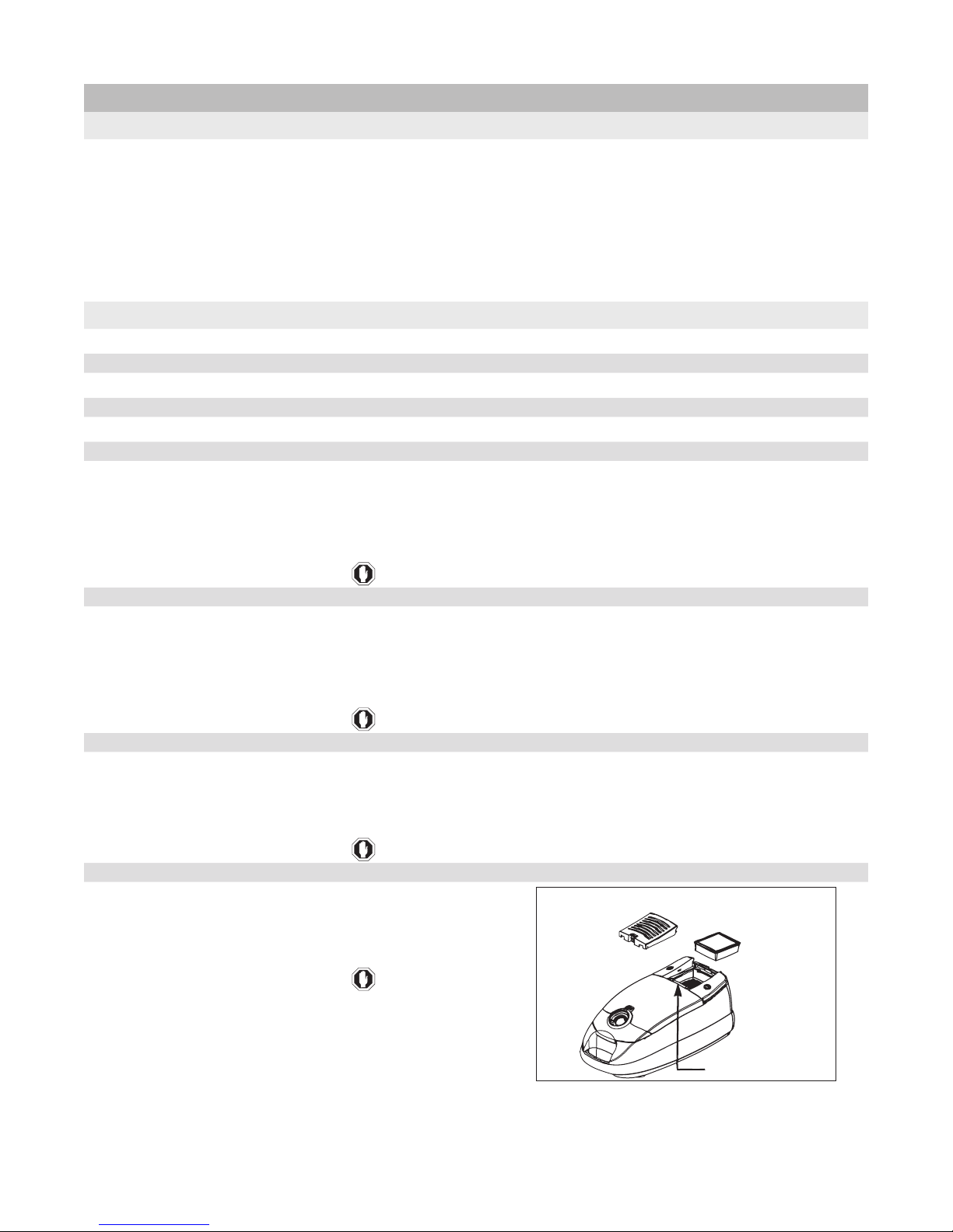
B. Check Filter Light
HEPA filter cover
S-Class HEPA filter
Reset Button
1. General information
The check lter mechanism works on a timer. When the canister has accumulated 25 hours of operating time, the PC board triggers the
check lter light to indicate the HEPA lter should be replaced. Pressing the “Reset” button will reset the timer and turn the light off.
If the light comes on before 25 hours of use, place the hose on a functional test canister or replace the faulty hose and recheck the light� If
the light stays on, verify when the lter was last changed and that the reset button was pressed afterward.
NOTE: Pushing the reset button should reset the timer and turn the light out�
2. The reset switch does not reset the check lter light.
Check the reset switch and wiring to PC connection board as follows:
B� Step 1.
Remove HEPA lter.
B� Step 2.
Remove the covers for the canister power switch and the cord rewind button (be careful not to lose the springs)�
B� Step 3.
1� Remove the 8 (eight) screws holding the black bracket in position, this will allow you to see the wiring� Check the wiring for
broken or pinched wires�
2� If all the wires are good continue to Step 4.
3� If necessary replace any bad wiring�
4� Re-assemble canister and re-test�
B� Step 4.
1� With the hose connected and canister plugged in, take a DC volt meter and check volts at the the PC connection board (red
wires) should read 4 to 5 volts DC�
2� If voltage is good continue to Step 5.
3� If voltage is not good replace the PC board�
4� Re-assemble canister and re-test�
B� Step 5.
Place the tester on the connector located on the reset switch� This should read -4 to -5 volts DC�
2� If voltage is good continue to Step 6.
3� If voltage is not good replace the wiring to the switch�
4� Re-assemble canister and re-test�
B� Step 6.
1� With volt meter reading -4 to -5 volts press the reset switch
and volts should go to zero the return to -4 to -5 volts� If the
voltmeter does not zero out for a moment the reset switch is bad
and should be replaced�
2� Re-assemble canister and re-test�
NOTE: You will also want to replace the PC board if the light is coming on
at less than 22 hours of operation�
Figure D. HEPA Reset Button Location.
3
I� General Full Size Canister Issues07�03�07
Page 6

C. Common Issues
1. Canister power switch does not click when pedal is depressed.
-This switch should NOT “click”� In a typical switch, such as the one on the mid-size canister, the click you hear is the movement of the metal
contact inside the switch� This contact remains either in contact - completing the circuit, or dis-connected - breaking the circuit� There is
no rocker or latch to hold the contacts in place in the full-size canister so you will not hear a “click”� The circuit is momentarily completed by
depressing the switch, sending a signal to the PC board� That signal is interpreted as an instruction to turn the canister “On”� Depressing
the switch a second time instructs the PC board to turn the canister “Off”�
2. What to check rst when canister will not power up.
-Dislodged electrical connectors are the usual cause of the canister not powering up� Make sure that all of the electrical connectors are
rmly and securely engaged. It only takes one dis-connection to interrupt the proper operation of the canister cleaner.
3. Interpreting blinking LED light on the main PC board.
-This light indicates whether the main PC board is maintaining proper communication with the handle PC board� The light should be
blinking at an approximate rate of 2 seconds on, 2 seconds off� If it is blinking at a faster rate of 0�5 seconds on, 0�5 seconds off, there is
an interruption in the communication between the two PC boards� If the light does not blink at all, there is a problem with the power being
supplied to the main PC board�
4. Canister will not run without the hose connected.
-The hose must be connected to complete the circuit before the canister will run� This is due to the variable control being mounted in the
handle assembly�
5. Canister cuts on and off at the customers house but runs in the store.
-The power at the home may vary due to the current load on the circuit� Wiring in the house may not be heavy enough to carry the load of
the canister plus the other items connected�
6. Canister cuts on and off when plugged into a power strip, but runs when plugged into the wall.
-The power strip breaker is not large enough to handle the 12 AMP canister for extended period of time�
4
I� General Full Size Canister Issues07�03�07
Page 7
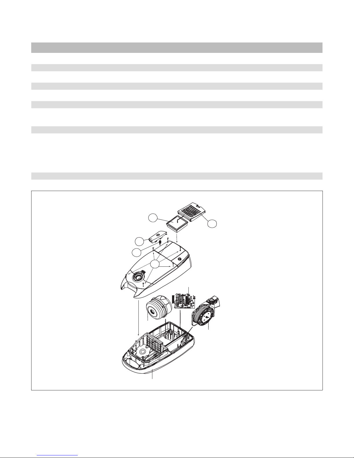
1
2
3
5
PC Board
Cord Reel
Main Seal
4
II. Full Size Canister Troubleshooting Guide
A. Cover Dis-assembly Instructions
Tools required: 6 inch #2 phillips and athead screw driver
A� Step 1.
Remove HEPA lter grill exhaust (See Figure A. Main Parts Assembly, )�
A� Step 2.
Remove HEPA lter (See Figure A. Main Parts Assembly, )�
A� Step 3.
Remove the canister power switch cover/pedal� The pedal has three catches/tabs to release it (See Figure A. Main Parts
Assembly, ) Be careful not to lose the switch foot spring (See Figure A. Main Parts Assembly, ) �
A� Step 4.
Remove the cover assembly screws (6) (See Figure A. Main Parts Assembly, ):
-one screw is under the HEPA lter,
-one screw is under the switch pedal,
-open the dust cover assembly there are two screws between the bag holder tabs and the handle,
-two screws are between the back wall of the dust compartment and the tool plate hinges
A� Step 5.
Lift the cover assembly up and dis-connect the wiring harness� (Squeeze the latches and pull apart�)
Figure A. Main Parts Assembly
5
II� Full Size Canister Troubleshooting Guide07�03�07
Page 8

B. Canister Shuts Off or Will Not Power Up
B� Step 1.
1� Check the power cord for damage�
2� Ensure the hose assembly is properly connected and re-test the canister�
3� If canister does not power up, continue to Step 2
B� Step 2.
1� Make sure the wall outlet is providing power and re-test the canister�
2� If canister does not power up, continue to Step 3
B� Step 3.
1� Remove the hose assembly�
2� Connect the original hose assembly to a known functional test canister and re-test using this canister�
3� If the test canister does not power up the original hose is defective� Replace the hose and re-test the original canister with the
new hose�
4� If the test canister powers up with the original hose:
• Dis-assemble the cover (See Page 5, A. Cover Dis-assembly Instructions Steps 1-3)
• Make sure both the black and white two wire connectors and wires are secure in their sockets on the PC connector board�
(Connectors are located under the foot pedal switch cover�) (See Figure A. Main Parts Assembly, )�
• Re-test canister�
5� If canister still does not power up, continue to Step 4.
B� Step 4.
1� Remove dust cover assembly� (See page 5, A. Cover Dis-assembly Instructions�)
2� Lift off top cover in order to see PC board�
3� Verify all electrical connections are securely made, including hose�
4� Ensure that the eight (8) wires are secure in the 9-pin connector�
5� Check for blinking LED light at the lower corner of the main PC board next to the cord reel�
6� If the LED light is blinking skip to Step 7.
7� If the LED light is NOT blinking:
• Check the fuse�
• If the fuse is good, continue to Step 5.
• If the fuse is bad, replace fuse – 12�5V 15A - and re-test the canister�
• Re-assemble canister if good�
B� Step 5.
1� Check the cord reel assembly:
•Remove cord reel�
•Check connector on cord reel for burnt spot�
•Plug into outlet and use test light or volt meter which should read 110-120 VOLTS�
2� If the cord reel tests good, continue to Step 6.
3� If the cord reel does NOT test good, replace the cord reel and then re-test the canister�
4� Re-assemble canister if good�
5� If there is still no power to the PC board go to Step 6.
6
II� Full Size Canister Troubleshooting Guide07�03�07
Page 9

B. Canister Shuts Off or Will Not Power Up - Continued
B� Step 6.
1� Check the wiring harness from the cord reel to the PC board:
On KV040526 and up the harness will split - the white lead will go to PC board and the blue lead to the thermal switch connector.
On KV040525 and below both harness leads will go to the PC board.
2� Install cord reel�
3� Ensure that power is dis-connected before you dis-connect the cord reel connector at PC board to prevent damaging the
connector�
4� Connect power cord to power source�
5� Plug test light into connector�
6� Check the connector end any for burnt spots inside the connector and the PC Board for any burnt spots on back�
If you have a KV040525 and lower, follow the same steps but do not test the thermal protector.
7� If you have power continue to Step 7.
8� If you do not have power:
• Model KV040526 and up – Change PC Board and check the LED light
• Model KV040525 and lower – follow same steps but do not test thermal protector�
9� Go to Step 7.
B� Step 7.
1� Check the LED blink rate�
2� If the LED is blinking slowly at 2 sec intervals skip to Step 13�
3� If the LED is blinking at a fast rate (0�5 sec intervals), make sure main wiring harness is securely connected�
4� Recheck the LED blink rate�
5� If the LED still blinking at fast rate? (0�5 second intervals) continue to Step 8, otherwise skip to Step 13.
B� Step 8.
1� Make sure the two-wire connectors on the PC connection board (under the switch pedal) are securely connected and that the
2� Verify that the hose is installed�
3� If the LED is still blinking at fast rate? (0�5 second intervals) continue to Step 9, otherwise skip to Step 13.
B� Step 9.
1� Remove cord reel pedal� (Do not lose pedal spring)
2� Remove eight (8) screws from the rear compartment bracket and remove the bracket from the top cover� (See Figure G. Cover
3� Remove dust compartment lid� (See page 5, A. Cover Dis-assembly Instructions�)
4� To inspect wiring the dust compartment lid must be separated from the dust compartment tool plate (See Figure H� Dust Cover
5� Inspect the wiring and connectors between the PC connection board and the hose cuff socket for damage or improper
6� If the wires and connectors are in good working condition skip to Step 11, if not continue to Step 10.
B� Step 10�
1� Replace any bad wires or connectors�
2� Re-assemble top cover, tool plate, etc�
3� Check for proper operation�
wires are secure in the connectors�
Assembly.
Assembly)� The hose cuff socket will have to be dis-assembled to check frame terminal assembly�
assembly�
4� If the LED is still blinking at fast rate (0�5 second intervals), continue to Step 11.
5� If the LED is blinking at normal rate – 2 second intervals, re-test the canister and re-assemble if good�
7
II� Full Size Canister Troubleshooting Guide07�03�07
Page 10

B. Canister Shuts Off or Will Not Power Up - Continued
B� Step 11.
1� Replace the PC connection board assembly (See Figure G. Cover Assembly )
2� Re-assemble the top cover, tool plate, etc�
3� Check for proper operation�
4� If the LED is still blinking at fast rate? (0�5 second intervals) skip to Step 13.
5� If the LED is blinking at normal rate – 2 second intervals, re-test the canister and re-assemble if good�
B� Step 12.
1� LED is Blinking slowly at 2 (two) second intervals and canister will not power up�
2� Test the motor – (Dis-connect the motor from the PC board and connect it to 110 VOLTS) MAKE SURE MOTOR IS SECURE
BEFORE CONNECTING�
3� If the motor runs go to Step 13.
4� If the motor does not run, check wires on motor�
5� If the wires are good, replace the motor and re-test the canister� Re-assemble if canister is good�
6� If the wires are bad, connect wires if able� If wires are broken off motor, replace motor and re-test� Re-assemble if canister is
good�
NOTE: If motor runs when hooked up direct but not when installed, and power nozzle runs –Model is KV040525 or below. Replace
thermal protector and re-test canister.
B� Step 13.
1� LED blinking fast at 0�5 second intervals OR LED blinking at 2 second intervals and canister will not power up�
2� Replace PC Board and re-test canister� Re-assemble if good�
C. Canister Power Switch Fails to Power Up Unit; Hose Works Normally
If the foot pedal On/Off switch:
1� Does not operate, or
2� Turns the unit On, but not Off, or
3� Turns the unit Off, but not On
Although the hose seems to be working normally, the handle PC board in the hose may be interfering with the operation of the main switch�
Attach the original hose to a functional test canister and verify that the On/Off switch works� If the test canister foot switch does not work,
the original hose if faulty and needs to be replaced�
8
II� Full Size Canister Troubleshooting Guide07�03�07
Page 11

D. Canister Runs - Power Nozzle Does Not Run
D� Step 1.
1� Swap original power nozzle, wand and hose assembly with those of a functional test canister - testing one original component
at a time�
2� If all original components are working properly with the test canister go to Step 2�
3� Replace defective component as necessary and re-test�
4� If the power nozzle works re-assemble the canister and re-test�
5� If the power nozzle does NOT work continue to Step 2.
D� Step 2.
1� Dis-assemble cover� (See page 5, A. Cover Dis-assembly Instructions Steps 1-3)
2� Make sure both the black and white two wire connectors and wires are secure in their sockets on the PC connector board�
(Connectors are located under the foot pedal switch cover�) (See Figure A. Main Parts Assembly, )�
3� Re-test the canister�
4� If the power nozzle works re-assemble the canister and re-test�
5� If the power nozzle does NOT work continue to Step 3.
D� Step 3.
1. Remove top cover held in place by six (6) screws located in deep pockets (one under HEPA lter, one under switch pedal, and
four under bag lid�)
D� Step 4.
D� Step 5.
2� Lift off top cover in order to see PC board�
3� Verify all electrical connections are secure, including hose�
4� Ensure that the eight (8) wires are secure in the 9-pin connector�
5� Check for blinking LED light at the lower side of the main PC board next to the cord reel�
6� If the LED is blinking slowly (2 second intervals), re-test the canister�
•If power nozzle works re-assemble�
•If power nozzle still does not work continue to Step 4.
7� If the LED is blinking fast (0�5 second intervals), the PC board is not communicating with the hose - lights in the handle should
not be “ON” continue to Step 4.
1� Replace main PC board with known working PC board�
2� Re-test canister�
3� If the power nozzle works, re-assemble the canister and re-test�
4� If the power nozzle does NOT work, continue to Step 5.
1� Remove cord reel pedal� (Do not lose pedal spring)
2� Remove 8 (eight) screws from the rear compartment bracket and remove the bracket from the top cover�
3� Replace PC connection board with known working PC connection board and re-test the canister�
4� If the power nozzle works, re-assemble the canister and re-test�
5� If the power nozzle does NOT work, continue to Step 6.
D� Step 6.
1� Remove dust cover assembly� (See page 5, A. Cover Dis-assembly Instructions�)
2� Inspect wiring and connectors between PC connection board and the hose cuff socket for damage or improper assembly�
3� Replace the PC connection board/ wiring harness and re-test�
9
II� Full Size Canister Troubleshooting Guide07�03�07
Page 12

E. Power Nozzle Cuts On and Off When Using - Troubleshooting Wand
Circuit Breaker Switch
NOTE: If warning light is red, there are no headlights, and power nozzle won’t run, press the reset button�
E� Step 1.
1� Turn the power nozzle ON�
2� Holding the hose handle with one hand, twist the wand with the other hand�
3� If the nozzle does not cut off continue to Step 2�
4� If the nozzle cuts off the problem is in the connection at the hose handle�
5� Replace connectors or hose and re-test the power nozzle�
E� Step 2.
1� Holding the wand with one hand, twist the nozzle with the other hand�
2� If the nozzle does not cut off continue to Step 3�
3� If the nozzle cuts off, the problem is in the connection at the lower end of the wand or the canister connection plug�
4� Change the wand and re-test� If good change the canister connection plug�
5� Re-assemble and re-test�
E� Step 3.
1� Holding the wand with one hand, hold the nozzle down and pull on the wand with the other hand�
2� If the nozzle cuts off:
a� Check the neck on the power nozzle to see if it is cracked or one of the prongs in the canister connection plug is pulled
loose or broken�
b� Check for wear on the catch in the neck assembly�
c� If neck is cracked or the catch is worn change the neck assembly�
d� If the prongs are broken, bent, or short (less than 10mm) replace the nozzle power cord�
3� If the nozzle does NOT cut off:
a� Check the play in the wand to neck assembly� If there is too much play, nozzle will cut out�
b� Try another wand and re-test and/or change out the neck�
Figure B. Power Nozzle Reset Switch Location
10
II� Full Size Canister Troubleshooting Guide07�03�07
Page 13

F. Power Nozzle w/ Dirt Sensor Will Not Run But Canister Runs
Dirt Sensor / Warning Light
F� Step 1.
Check the hose to see if the light indicates that the nozzle is on�
F� Step 2.
Check the nozzle to see if the sensor/indicator light is “ON”, and if on what color is it�
F� Step 3.
F� Step 4.
Light is OFF:
Light is RED:
Light is GREEN:
Light is ORANGE:
NOTE: If the motor is not running there will be no headlight�
Push the reset switch/breaker (See Figure B. Power Nozzle Reset Switch Location)�
Turn the power nozzle “ON”�
Does the nozzle start, the indicator light turn GREEN, and the headlight come on?
YES: Check the height adjustment to ensure it is set to proper height for the type of carpet being vacuumed�
NO: If breaker continues to trip, the breaker may be weak and should be replaced�
NOTE: If light is RED and power nozzle runs - Check wiring (See Figure L� Wiring Diagram For Dirt Sensor Models)�
Turn the canister and power nozzle “ON”; push the nozzle through some dirt and see if the light turns ORANGE�
Light turns ORANGE: Sensor is working and breaker/reset switch is good�
Light stays GREEN: Remove nozzle and cover and check the motor and wiring to the motor and that the sensors are in place�
Go to page 10, D. Canister Runs, Power Nozzle Does Not Run
Go to Step 3.
Go to Step 4.
Go to Step 5.
Remove nozzle and cover and check the motor and wiring to the motor�
Check movement of wiring when handle is moved up and down� If sensor moves, remove sensor leads
from zip tie�
F� Step 5.
ORANGE light normally indicates that dirt has been found�
If light stays ORANGE it indicates that the sensor has dirt or moisture on the sensor lens located one on each side of the inlet
duct�
Clean lens by rst removing the base plate and brush roll. Using a paper towel, reach up and wipe the dirt/moisture from the
lens�
After cleaning, the light should change to GREEN�
NOTE: If the indicator light is ORANGE and motor is not running, check the motor and wiring to the motor�
Figure C. Power Nozzle Warning Light & Dirt Sensor Location
11
II� Full Size Canister Troubleshooting Guide07�03�07
Page 14

G. Power Nozzle w/ Dirt Sensor Runs But Indicator Light Will Not Change
Light is Green:
Indicator light stays GREEN even when the nozzle is pushed through dirt�
Check the wires between the PC board and the sensors to ensure that they are connected and not pinched�
Light is Red:
Check to ensure that the sensors are wired correctly�
RED light is on and the power nozzle is running:
1� Stop power nozzle�
2� Place a lock on the motor (with a pair of vice grips) or jam the agitator�
WARNING: If vice grips are used to lock motor, ensure they are lying at against housing before starting motor.
3� Turn power nozzle on�
4� If the light turns GREEN the sensors are wired wrong�
5� Change the dirt sensor PC board and sensors assembly�
Light is Orange:
ORANGE light normally indicates that dirt has been found�
Light stays ORANGE:
1� If light stays ORANGE it indicates that the sensor has dirt or moisture on the sensor lens located one on each side of the inlet
duct�
2. Clean lens by rst removing the base plate and brush roll. Using a paper towel, reach up and wipe the dirt/moisture from the
lens�
3� After cleaning, the light should change to GREEN�
12
II� Full Size Canister Troubleshooting Guide07�03�07
Page 15

H. Wire Harness Upgrade Instructions
H� Step 1. Remove cover assembly.
1� See page 5, A. Cover Dis-assembly Instructions Steps 1-5
H� Step 2� Remove cord reel assembly and wiring harness.
1� Lift cord reel assembly up, dis-connect the connector, and set aside�
2� Dis-connect the wiring harness from the PC board, lift body seal and slide harness out of canister� Throw old harness away�
H� Step 3� Upgrade wiring harness and install motor assembly.
1� Dis-connect motor wiring harness from the main PC board (Red connector)�
2� Lift motor assembly out of canister�
3� Remove the 4 screws holding the motor assembly together and separate the two halves�
4� Remove the two blue leads from the motor connectors and throw the old harness away�
5� Replace with new wiring harness, which will go straight to the PC board�
6� Remove the wiring harness on the thermal switch (thermostat) and replace it with the new harness, (which will plugs into the
wiring harness between the cord reel and the PC board)�
7� Put the motor back into the motor housing/mounts and install four screws (ensure that the wiring harness is in the slots in the
side of motor housing/mount)�
8. Ensure the rubber tube is connected between the dust compartment and PC board. (Connects to the white tting on the
sensor)
9� Install the motor�
10� Connect motor wires to the PC board� The red connector connects to the to pink connector on PC board�
H� Step 4� Replace cord reel wiring harness.
1� Install P/N 3622714720 new wiring harness� Lift rubber body seal and slide connector under and into slot in dust compartment�
Push rubber seal back into place� Place connector into slot under the cord reel with the wiring going to outside slot� (Connector
should be cross-ways inside of canister)
2� Connect the black connector on the new harness to the black connector on the thermal switch�
3� Connect the clear/yellowish connector to the white connector on the PC board�
4� Install the cord reel by pushing it down into position, while making sure the connectors line up�
Prior to installing the top cover check all connectors and position the main wiring harness 9-pin connector into the slot, (tabs
should be toward PC board and handle). The 9-pin connector on the cover assembly should be placed into the slot with the
locking tabs positioned to the inside and outside of the canister. Once the connectors are in place go to Step 5.
H� Step 5� Install top Cover
1� Place top cover into position, if the connectors are in their slots, they should line up� If you do not have a bag installed, you
will have to position the bag holder down to get the front to seat against the seal� Ensure the top cover is down against the
seal before proceeding�
2� Install 6 screws into the top cover (See Figure A. Main Parts Assembly, )�
3� Install the main switch cover making sure that the spring is in place (See Figure A. Main Parts Assembly, & )�
4. Install the HEPA lter and push the reset button (See Figure A. Main Parts Assembly, )�
5. Install the HEPA lter exhaust grill (See Figure A. Main Parts Assembly, )�
13
II� Full Size Canister Troubleshooting Guide07�03�07
Page 16

E. Main Parts
III. Full Size Canister Figures
NO PART NAME
1 Body Assembly
2 Motor Assembly
3 Cord Reel Assembly
4 Cord Reel Lever
5 Cord Reel Roller Wheel
6 Screw*
7 Spring for Lever*
8 Main PCB Assembly
9 Cover Assembly
10 PC Board Fuse
11 Screw Tapping
12 Spring Button
13 Button Switch
14 Hepa Filter
15 Grill Exhaust
16 Bag Filter
17 Hose Assembly
18 Power Brush Assembly
19 Pedal Brush Assembly
20 Floor Brush Assembly
21 Pipe Assembly
*Parts of Cord Reel Assembly
14
III� Full Size Canister Figures07�03�07
Page 17

F. Body Assembly
NO PART NAME
1 Dust Compartment
2 Caster Shaft
3 Screw
4 Caster Body
5 Caster Wheel
6 Caster Wheel Axle
7 Parking Bracket
8 Screw
9 Wire Harness
10 Furniture Guard
11 Handle Insert
12 Bag Holder Assembly
12a Bag Holder
12b Bag Holder Spring
13 Dust Compartment Gasket
14 Secondary Filter Holder
15 Activated Charcoal Filter
16 Bottom Motor Mount
17 Front Motor Mount
18 Cover Hole
19 Screw
20 Silicone Rubber
21 Cord Reel Assembly
15
III� Full Size Canister Figures07�03�07
Page 18

G. Cover Assembly
NO PART NAME
1 Upper Compartment Body
2 Upper Motor Mount
3 Motor Foam Filter
4 Main On/Off Switch
5 Filter reset Button
6 Screw
7 PC Board Connector Assembly
8 PC Board Mount
9 Cover Dust Assembly
10 Rear Compartment Bracket
11 Screw Tapping
12 Cord Reel Spring
13 On/Off Button
14 Cord Reel Button
15 S-Class HEPA Filter
(Includes seal)
16 Post Filter Cover
16
III� Full Size Canister Figures07�03�07
Page 19

H. Dust Cover Assembly
NO PART NAME
1 Dust Compartment Lid
2 Dust Compartment Tool Plate
3 Frame Terminal Assembly
4 Hose Cuff Socket
5 Dust Cover Latch
6 Tool Lid Latch
7 Tool Cover Latch
8 Latch Spring
9 Tool Cover Lid Dampener
10 Screw
11 Screw
12 Tool Cover Lid Spring
13 Tool Lid
14 Tool Lid Hinge
17
III� Full Size Canister Figures07�03�07
Page 20

J. Hose Assembly
NO PART NAME
1 Hose Assembly
2 PCB Y Terminal Assembly
3 PCB Handle Assembly
4 Cover Handle Right
5 Cover Handle Left
6 Screw
7 Pipe Handle Inner
8 Cap Cover Handle
9 Terminal Subassembly
10 Screw
11 Hose Handle Decal
18
III� Full Size Canister Figures07�03�07
Page 21

Motor
Thermal Reset
Cord Reel
PC Board
Black
Black
White
Blue
Blue
RedWhite
K. Wiring Diagram for Harness Upgrade
19
III� Full Size Canister Figures07�03�07
Page 22

L. Wiring Diagram For Dirt Sensor Models
M
Motor
Power Cord
Circuit
Breaker
PC
Board
White
White
White
Black
Brown
Black
Brown
or Red
Black
Red
Red
Brown
or Red
Brown
M
Motor
Canister Connection Plug
Circuit
Breaker
LED Light
Red or Brown or Black
Black
Black
Red
Red
Green
Brown
Brown
White
White
White
Red or Brown or Black
M. Wiring Diagram For Non-Dirt Sensor Models
20
III� Full Size Canister Figures07�03�07
 Loading...