Simplicity 7016, Landlord 1690016, Sovereign 1690086 Operator's Manual

Page 1

SYSTEM & SYSTEM 7010 7016

1690016 LANDLORD 10 H.P. 3 SP. 1690086 SOVEREIGN 16 H.P. 3 SP.

FORM – 1651908 PRINTED IN U.S.A. 748

Page 2
TO THE OWNER

Congratulations on your purchase of the Simplicity tractor. It has been designed with emphasis on the ability to do your most important jobs quickly and efficiently with the least operator effort.

So that you can get the very most from your purchase, you and anyone else who may operate the tractor should study this manual and the owners manual for your attachments before using your Simplicity tractor. Throughout the manual, we will refer to directions as left, right, front, and rear. These directions are as the operator sits on the tractor seat in the driving position.

For your own safety and that of your family and others, periodically review the safety tips found in this manual. You will find the table of contents very useful in referring to this manual when questions arise in the future. We have provided you with information to perform most service jobs quickly and easily, but your Simplicity dealer will be happy to help you with any service or repair work.

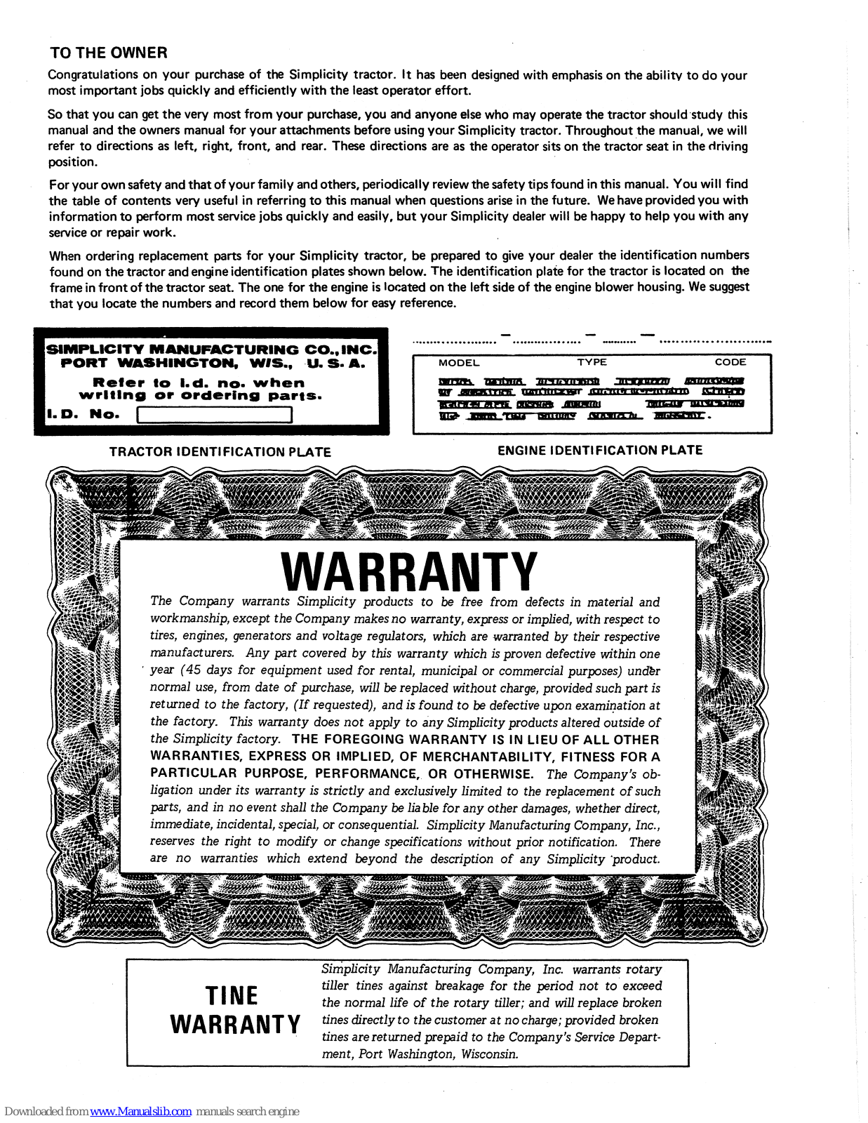
When ordering replacement parts for your Simplicity tractor, be prepared to give your dealer the identification numbers found on the tractor and engine identification plates shown below. The identification plate for the tractor is located on the frame in front of the tractor seat. The one for the engine is located on the left side of the engine blower housing. We suggest that you locate the numbers and record them below for easy reference.

SIMPLICITY MANUFACTURING CO., INC. PORT WASHINGTON, W/S., U.S.A. Refer to I.d. no. when writing or ordering parts. I.D. No.

TRACTOR IDENTIFICATION PLATE
ENGINE IDENTIFICATION PLATE

The Company warrants Simplicity products to be free from defects in material and

workmanship, except the Company makes no warranty, express or implied, with respect to tires, engines, generators and voltage regulators, which are warranted by their respective manufacturers. Any part covered by this warranty which is proven defective within one year (45 days for equipment used for rental, municipal or commercial purposes) under normal use, from date of purchase, will be replaced without charge, provided such part is returned to the factory, (If requested), and is found to be defective upon examination at the factory. This warranty does not apply to any Simplicity products altered outside of the Simplicity factory. THE FOREGOING WARRANTY IS IN LIEU OF ALL OTHER WARRANTIES, EXPRESS OR IMPLIED, OF MERCHANTABILITY, FITNESS FOR A PARTICULAR PURPOSE, PERFORMANCE, OR OTHERWISE. The Company's obligation under its warranty is strictly and exclusively limited to the replacement of such parts, and in no event shall the Company be liable for any other damages, whether direct, immediate, incidental, special, or consequential. Simplicity Manufacturing Company, Inc., reserves the right to modify or change specifications without prior notification. There are no warranties which extend beyond the description of any Simplicity product.

Simplicity Manufacturing Company, Inc. warrants rotary tiller tines against breakage for the period not to exceed the normal life of the rotary tiller; and will replace broken tines directly to the customer at no charge; provided broken tines are returned prepaid to the Company's Service Department, Port Washington, Wisconsin.

Page 3
WARRANTY INSIDE COV
PROTECT YOURSELF AND OTHERS 1
OPERATION 2
INSTRUMENTS AND CONTROLS 2
BEFORE OPERATING THE TRACTOR 4
STARTING THE ENGINE 5
STOPPING THE ENGINE 5
CONTROLLING TRACTOR GROUND SPEED 5
OPERATION CHART 7
TROUBLE SHOOTING GUIDE 8
HOT WEATHER OPERATION 9
COLD WEATHER OPERATION 9
DUSTY OPERATING CONDITIONS 9
OUT OF SERVICE PROTECTION (STORAGE) 9
STARTING THE TRACTOR AFTER STORAGE 9
ADJUSTMENTS 10
RAISING TRACTOR HOOD 10
RAISING THE SEAT DECK
SEAT ADJUSTMENT 10
. •
CLUTCH FREE TRAVEL 11
DRIVE BELT STOP ADJUSTMENT 11
FOOT PEDAL BRAKE ADJUSTMENT 11
PARKING BRAKE ADJUSTMENT 12
TRANSMISSION NEUTRAL SAFETY • •
START SWITCH 12
POWER TAKE - OFF CLUTCH ADJUSTMENT 13
STARTER - GENERATOR BELT ADJUSTMENT 13
CARBURETOR ADJUSTMENT 13
MAINTENANCE
ORDERING REPLACEMENT PARTS
EVERY 5 HOURS OF OPERATION
EVERY 25 HOURS OF OPERATION
EVERY 100 HOURS OR ONCE A YEAR
SCHEDULED MAINTENANCE CHART
15
15
15
15
18
18
ACCESSORIES
ATTACHMENTS
PARTS LISTING
PARTS LISTING FOR MAJOR ATTACHMENTS
20
20
21
42
SAFETY PRECAUTIONS TO PROTECT YOURSELE AND OTHERS
OPERATION

Know the controls and how to stop quickly - READ THE OWNER'S MANUAL

Do not allow children to operate vehicle. Do not allow adults to operate it without proper instruction.

Do not carry passengers. KEEP CHILDREN AND PETS A SAFE DISTANCE AWAY.

Clear work area of objects which might be picked up and

Take all possible precautions when leaving vehicle unattended; such as disengaging power-take-off, lowering attachments, shifting into neutral, setting parking brake. stopping engine and removing key.

Do not stop or start suddenly when going uphill or down hill. Mow up and down the face of steep slopes; never across the face.

Reduce speed on slopes and in sharp turns to prevent tipping or loss of control. Exercise extreme caution when changing direction on slopes.

Stav alert for holes in terrain and other hidden hazards.

Use care when pulling loads or using heavy equipment. A. Use only approved drawbar hitch points.

  • Limit loads to those you can safely control. Do not turn sharply. Use care when backing. Use counterweight (s) or wheel weights when suggested in owner's manual.

Watch out for traffic when crossing or near roadways.

Keep all nuts, bolts, and screws tight to be sure equipment is in safe working condition.

Do not alter basic engine governor settings or overspeed engine.

Do not operate equipment when barefoot or wearing open sandals. Always wear substantial footwear.

FUEL & FIRE HAZARDS

Handle gasoline with care – it is highly flammable. A. Use approved gasoline container.

  • Never remove cap or add gasoline to a running or hot engine or fill fuel tank indoors. Wipe up spilled

  • Open doors if engine is run in garage exhaust fumes are dangerous. Do not run engine indoors.

Never store equipment with gasoline in the tank inside a building where fumes may reach an open flame or spark.

Allow engine to cool before storing in any enclosure.

To reduce fire hazard keep engine free of grass, leaves or excessive grease.

ATTACHMENTS

Disengage all attachment clutches and shift into neutral before attempting to start engine.

Disengage power to attachments and stop engine before leaving operator position.

Disengage power to attachment (s) and stop engine before making any repairs or adjustments.

Disengage power to attachments when transporting or not

When using any attachments never direct discharge of material toward bystanders or allow anyone near vehicle while in operation.

Keep vehicle and attachments in good operating condition and keep safety devices in place. Use guards as instructed in owner's manual.

Vehicle and attachments should be stopped and inspected for damage after striking a foreign object and the damage should be repaired before restarting and operating the equipment.

When using vehicle with mower

  • (1) Mow only in daylight or in good artificial light
  • (1) Now only in dayight of in global at the an ight. (2) Never make a cutting height adjustment while engine is running if operator must dismount to do so. (3) Shut engine off when uncloqging chute.
  • (4) Check blade mounting bolts for proper tightness at frequent intervals.

If the equipment should start to vibrate abnormally, stop the engine and check immediately for the cause. Vibration is generally a warning of trouble.

Page 4

OPERATION

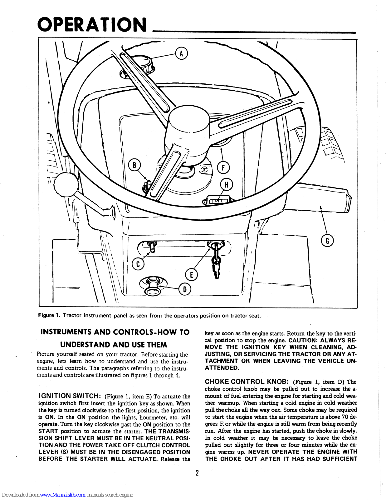
Figure 1. Tractor instrument panel as seen from the operators position on tractor seat.

INSTRUMENTS AND CONTROLS-HOW TO UNDERSTAND AND USE THEM

Picture yourself seated on your tractor. Before starting the engine, lets learn how to understand and use the instruments and controls. The paragraphs referring to the instruments and controls are illustrated on figures 1 through 4.

IGNITION SWITCH: (Figure 1, item E) To actuate the ignition switch first insert the ignition key as shown. When the key is turned clockwise to the first position, the ignition is ON. In the ON position the lights, hourmeter, etc. will operate. Turn the key clockwise past the ON position to the START position to actuate the starter. THE TRANSMIS-SION SHIFT LEVER MUST BE IN THE NEUTRAL POSI-TION AND THE POWER TAKE OFF CLUTCH CONTROL LEVER (S) MUST BE IN THE DISENGAGED POSITION BEFORE THE STARTER WILL ACTUATE. Release the

key as soon as the engine starts. Return the key to the vertical position to stop the engine. CAUTION: ALWAYS RE-MOVE THE IGNITION KEY WHEN CLEANING, AD-JUSTING, OR SERVICING THE TRACTOR OR ANY AT-TACHMENT OR WHEN LEAVING THE VEHICLE UN-ATTENDED.

CHOKE CONTROL KNOB: (Figure 1, item D) The choke control knob may be pulled out to increase the amount of fuel entering the engine for starting and cold weather warmup. When starting a cold engine in cold weather pull the choke all the way out. Some choke may be required to start the engine when the air temperature is above 70 degrees F. or while the engine is still warm from being recently run. After the engine has started, push the choke in slowly. In cold weather it may be necessary to leave the choke pulled out slightly for three or four minutes while the engine warms up. NEVER OPERATE THE ENGINE WITH THE CHOKE OUT AFTER IT HAS HAD SUFFICIENT

Page 5
TIME TO WARM UP - ABOUT 5 MINUTES SHOULD BE SUFFICIENT EVEN IN COLD WEATHER.

AMMETER: (Figure 1, item F) The dial pointer will move right to the "Charging" position when energy is being added to the battery and left to the "Discharge" position when energy is being drawn from the battery. The pointer will normally fluctuate to either side of the dial center.

HOURMETER: (OPTIONAL) (Figure 1, item H) The hourmeter is designed to record the number of hours the engine runs. However, since it is electrically operated, it will run any time the ignition switch is in the ON position even though the engine may not be running. The hourmeter is useful in keeping accurate maintenance records, and also a convenient way of telling how much time the tractor has been used on a particular job.

FUEL GAUGE AND FILLER CAP: (Figure 1, item A) The fuel gauge indicates the amount of fuel in the tank. Before adding fuel, shut off the engine and allow it to cool. To remove the fuel gauge and filler cap for adding gasoline, turn the fuel filler gauge-cap counter-clockwise. The fuel tank holds approximately 3 gallons - enough for about 3 hours of mowing. Use leaded or non-leaded "regular" grade automotive gasoline. CAUTION: DO NOT ALLOW LIGHTED CIGARETTES, MATCHES, ETC., AROUND ANY OPEN GASOLINE CONTAINER. DO NOT OVERFILL; WIPE UP ANY SPILLED GASOLINE.

LIGHT SWITCH: OPTIONAL ON 10 H.P.(Figure 1, item C). The switch should be moved up to the ON position to turn on the tractor lights. To prevent the lights from being turned on by unauthorized persons, the ignition switch must also be in the ON position for the lights to operate. To turn the light off, push the light switch down to the OFF position. DO NOT OPERATE THE LIGHTS FOR LONG PERIODS OF TIME (MORE THAN 20 MINUTES) WHEN THE AMMETER READS DISCHARGE OR THE BATTERY MAY DISCHARGE ENOUGH SO IT WILL NOT START THE ENGINE.

POWER LIFT SWITCH: (OPTIONAL) (Figure 1, item B) The power lift switch controls the electrically operated power lift unit. Push the toggle switch forward when you wish to raise a front center or rear mounted attachment. Pull it back toward you to lower the attachments. The power lift will stop and hold in any position when you release the toggle switch. The height indicator (Figure 6, item A) on the left side of the tractor can be used to determine what position the lift is in. The lift motor will ratchet when it has reached the end of its travel. Ratcheting is not harmful to the unit, but you should release the toggle switch as soon as ratcheting begins to prevent unnecessary wear. If the motor is allowed to ratchet for an extended period of time, a circuit breaker will open, disconnecting power to the lift motor. It will automatically reset after about a minute.

CLUTCH AND BRAKE PEDAL: (Figure 1, item G) Depressing the pedal will first disengage the tractor drive clutch. As you continue to depress the pedal, the brakes will be applied to stop the tractor.

TRANSMISSION SHIFT LEVER: (Figure 2, item A) The transmission shift lever is used to select the desired transmission gear speed and direction. There are three forward and one reverse position. The approximate ground speed in miles per hour for each at full engine speed (3600 RPM) is shown below:

GEAR STANDARD LOW SPEED KIT INSTALLED
First 1.5 MPH .96 MPH
Second 3.5 MPH 2.3 MPH
Third 5.8 MPH 3.7 MPH
Reverse 2.9 MPH 1.9 MPH

The diagram printed on the tractor frame shows the location of each position. To shift the transmission into reverse or second, pull the shift lever back toward you, then push it all the way to the right or left into the desired position. To shift into first or third, push the shift lever forward and move it left or right all the way to the desired position. Do not attempt to move the shift lever unless the foot pedal (Figure 1, item G) is depressed and tractor motion is stopped. The shift lever must be in the neutral START position for the engine to start.

PARKING BRAKE LOCK: (Figure 2, item B) To lock the parking brake grasp the lock, and pull it upward and back until the handle rests against the foot rest as shown in figure 2. To release pull the top portion away from the foot rest and down. It should be locked in the up position to prevent the tractor from rolling whenever the operator leaves the tractor seat.

SPEED CONTROL LEVER: (Figure 2, item C) The engine speed control lever is used to set the desired engine

Figure 2. Controls on left side of tractor.

Page 6

speed. The speed control lever should be moved forward away from the operator to increase engine speed or back toward the operator to reduce engine speed. Consult the appropriate section of this manual for specific information on suggested settings of the engine speed control lever. For example: starting the engine, page 5. Controlling tractor ground speed page 5, and the Operation Chart on page 7.

POWER TAKE OFF CONTROL LEVER: (Figure 2 item D) This power take off lever controls power to center or rear mounted attachments such as a mower or rotary tiller which are driven by the power take off. Pull the lever up and move it forward until it snaps over center to engage the power take off. Pull it back and down to disengage. The tractor engine should be running at 1/2 to full engine speed when the power take off is engaged to absorb the added load. CAUTION: ALWAYS DISENGAGE THE POWER TAKE OFF, AND WAIT UNTIL ALL ATTACHMENTS HAVE STOPPED MOVING BEFORE LEAVING THE TRACTOR SEAT. The power take off control lever must be disengaged before the engine will start. Always move the lever all the way to the engaged or disengaged position.

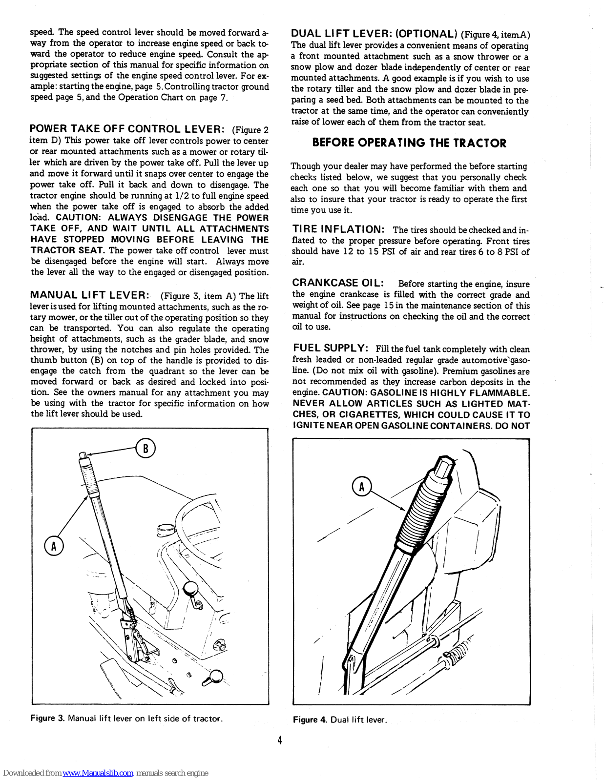
MANUAL LIFT LEVER: (Figure 3, item A) The lift lever is used for lifting mounted attachments, such as the rotary mower, or the tiller out of the operating position so they can be transported. You can also regulate the operating height of attachments, such as the grader blade, and snow thrower, by using the notches and pin holes provided. The thumb button (B) on top of the handle is provided to disengage the catch from the quadrant so the lever can be moved forward or back as desired and locked into position. See the owners manual for any attachment you may be using with the tractor for specific information on how the lift lever should be used.

Figure 3. Manual lift lever on left side of tractor.

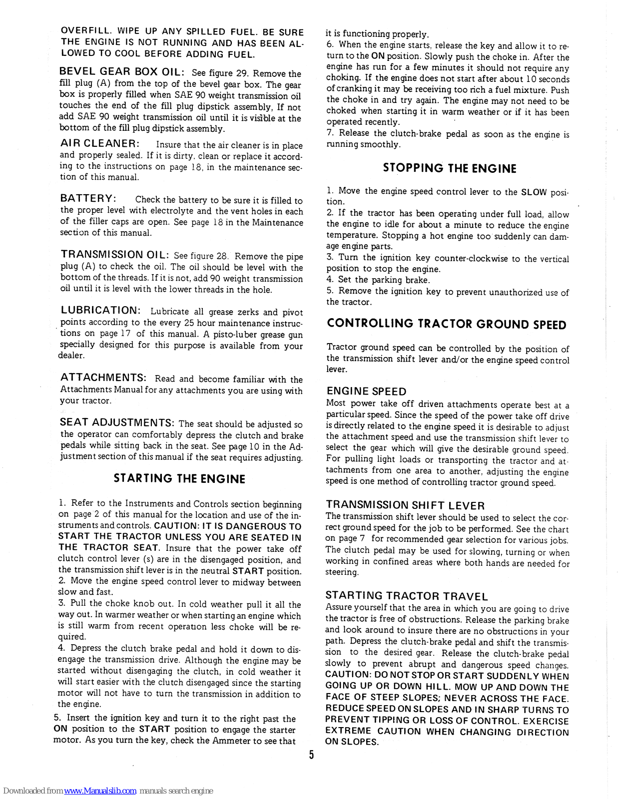
DUAL LIFT LEVER: (OPTIONAL) (Figure 4, itemA) The dual lift lever provides a convenient means of operating a front mounted attachment such as a snow thrower or a snow plow and dozer blade independently of center or rear mounted attachments. A good example is if you wish to use the rotary tiller and the snow plow and dozer blade in preparing a seed bed. Both attachments can be mounted to the tractor at the same time, and the operator can conveniently raise of lower each of them from the tractor seat.

BEFORE OPERATING THE TRACTOR

Though your dealer may have performed the before starting checks listed below, we suggest that you personally check each one so that you will become familiar with them and also to insure that your tractor is ready to operate the first time you use it.

TIRE INFLATION: The tires should be checked and inflated to the proper pressure before operating. Front tires should have 12 to 15 PSI of air and rear tires 6 to 8 PSI of air.

CRANKCASE OIL: Before starting the engine, insure the engine crankcase is filled with the correct grade and weight of oil. See page 15 in the maintenance section of this manual for instructions on checking the oil and the correct oil to use.

FUEL SUPPLY: Fill the fuel tank completely with clean fresh leaded or non-leaded regular grade automotive 'gasoline. (Do not mix oil with gasoline). Premium gasolines are not recommended as they increase carbon deposits in the engine. CAUTION: GASOLINE IS HIGHLY FLAMMABLE. NEVER ALLOW ARTICLES SUCH AS LIGHTED MAT-CHES, OR CIGARETTES, WHICH COULD CAUSE IT TO IGNITE NEAR OPEN GASOLINE CONTAINERS. DO NOT

Figure 4. Dual lift lever.

4

Page 7

OVERFILL. WIPE UP ANY SPILLED FUEL. BE SURE THE ENGINE IS NOT RUNNING AND HAS BEEN AL-LOWED TO COOL BEFORE ADDING FUEL.

BEVEL GEAR BOX OIL: See figure 29. Remove the fill plug (A) from the top of the bevel gear box. The gear box is properly filled when SAE 90 weight transmission oil touches the end of the fill plug dipstick assembly. If not add SAE 90 weight transmission oil until it is visible at the bottom of the fill plug dipstick assembly.

AIR CLEANER: Insure that the air cleaner is in place and properly sealed. If it is dirty, clean or replace it according to the instructions on page 18, in the maintenance section of this manual.

BATTERY: Check the battery to be sure it is filled to the proper level with electrolyte and the vent holes in each of the filler caps are open. See page 18 in the Maintenance section of this manual.

TRANSMISSION OIL: See figure 28. Remove the pipe plug (A) to check the oil. The oil should be level with the bottom of the threads. If it is not, add 90 weight transmission oil until it is level with the lower threads in the hole.

LUBRICATION: Lubricate all grease zerks and pivot points according to the every 25 hour maintenance instructions on page 17 of this manual. A pisto-luber grease gun specially designed for this purpose is available from your dealer.

ATTACHMENTS: Read and become familiar with the Attachments Manual for any attachments you are using with your tractor.

SEAT ADJUSTMENTS: The seat should be adjusted so the operator can comfortably depress the clutch and brake pedals while sitting back in the seat. See page 10 in the Adjustment section of this manual if the seat requires adjusting.

STARTING THE ENGINE

1. Refer to the Instruments and Controls section beginning on page 2 of this manual for the location and use of the instruments and controls. CAUTION: IT IS DANGEROUS TO START THE TRACTOR UNLESS YOU ARE SEATED IN THE TRACTOR SEAT. Insure that the power take off clutch control lever (s) are in the disengaged position, and the transmission shift lever is in the neutral START position. 2. Move the engine speed control lever to midway between slow and fast.

3. Pull the choke knob out. In cold weather pull it all the way out. In warmer weather or when starting an engine which is still warm from recent operation less choke will be required.

4. Depress the clutch brake pedal and hold it down to disengage the transmission drive. Although the engine may be started without disengaging the clutch, in cold weather it will start easier with the clutch disengaged since the starting motor will not have to turn the transmission in addition to the engine.

5. Insert the ignition key and turn it to the right past the ON position to the START position to engage the starter motor. As you turn the key, check the Ammeter to see that

it is functioning properly.

6. When the engine starts, release the key and allow it to return to the ON position. Slowly push the choke in. After the engine has run for a few minutes it should not require any choking. If the engine does not start after about 10 seconds of cranking it may be receiving too rich a fuel mixture. Push the choke in and try again. The engine may not need to be choked when starting it in warm weather or if it has been operated recently.

7. Release the clutch-brake pedal as soon as the engine is running smoothly.

STOPPING THE ENGINE

1. Move the engine speed control lever to the SLOW position.

2. If the tractor has been operating under full load, allow the engine to idle for about a minute to reduce the engine temperature. Stopping a hot engine too suddenly can damage engine parts.

3. Turn the ignition key counter-clockwise to the vertical position to stop the engine.

4. Set the parking brake.

5. Remove the ignition key to prevent unauthorized use of the tractor.

CONTROLLING TRACTOR GROUND SPEED

Tractor ground speed can be controlled by the position of the transmission shift lever and/or the engine speed control lever.

ENGINE SPEED

Most power take off driven attachments operate best at a particular speed. Since the speed of the power take off drive is directly related to the engine speed it is desirable to adjust the attachment speed and use the transmission shift lever to select the gear which will give the desirable ground speed. For pulling light loads or transporting the tractor and attachments from one area to another, adjusting the engine speed is one method of controlling tractor ground speed.

TRANSMISSION SHIFT LEVER

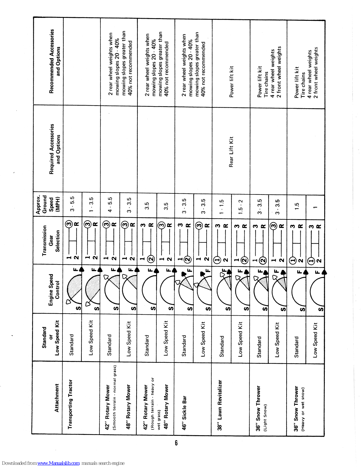
The transmission shift lever should be used to select the correct ground speed for the job to be performed. See the chart on page 7 for recommended gear selection for various jobs. The clutch pedal may be used for slowing, turning or when working in confined areas where both hands are needed for steering.

STARTING TRACTOR TRAVEL

Assure yourself that the area in which you are going to drive the tractor is free of obstructions. Release the parking brake and look around to insure there are no obstructions in your path. Depress the clutch-brake pedal and shift the transmission to the desired gear. Release the clutch-brake pedal slowly to prevent abrupt and dangerous speed changes. CAUTION: DO NOT STOP OR START SUDDENLY WHEN GOING UP OR DOWN HILL. MOW UP AND DOWN THE FACE OF STEEP SLOPES; NEVER ACROSS THE FACE. REDUCE SPEED ON SLOPES AND IN SHARP TURNS TO PREVENT TIPPING OR LOSS OF CONTROL. EXERCISE EXTREME CAUTION WHEN CHANGING DIRECTION ON SLOPES.

Page 8
Attachment Standard
or
Low Speed Kit
Engine Speed
Control
Transmission
Gear
Selection
Approx.
Ground
Speed
(MPH)
Required Accessories
and Options
Recommended Accessories
and Options
Transporting Tractor Standard S 3 - 5.5 -
Low Speed Kit S 1 - 3.5
42'' Rotary Mower
(Smooth terrain - normal grass)
Standard S 4 - 5.5 2 rear wheel weights when
mowing slopes 20 - 40%
48" Rotary Mower Low Speed Kit s 3 - 3.5 mowing slopes greater than
40% not recommended
42'' Rotary Mower
(Rough terrain - heavy or
Standard S 3.5 2 rear wheel weights when
mowing slopes 20 - 40%
wet grass)
48'' Rotary Mower
Low Speed Kit S 3.5 mowing slopes greater than
40% not recommended
46" Sickle Bar Standard S 3 - 3.5 2 rear wheel weights when
mowing slopes 20 - 40%
Low Speed Kit S 3 - 3.5 mowing slopes greater than
40% not recommended
38" Lawn Revitalizer Standard S 1 - 1.5 Rear Lift Kit Dowor lift Lit
Low Speed Kit S 1.5 - 2
36" Snow Thrower
(Light Snow)
Standard S 3 - 3.5 Power lift kit
Tire chains
Low Speed Kit S 3 - 3.5 4 rear wheel weights
2 front wheel weights
36" Snow Thrower
(Heavy or wet snow)
Standard S 23 1.5 Power lift kit
Tire chains
Low Speed Kit S 2
|| 3
R
4 rear wheel weights
2 front wheel weights

Downloaded from www.Manualslib.com manuals search engine

6

Page 9
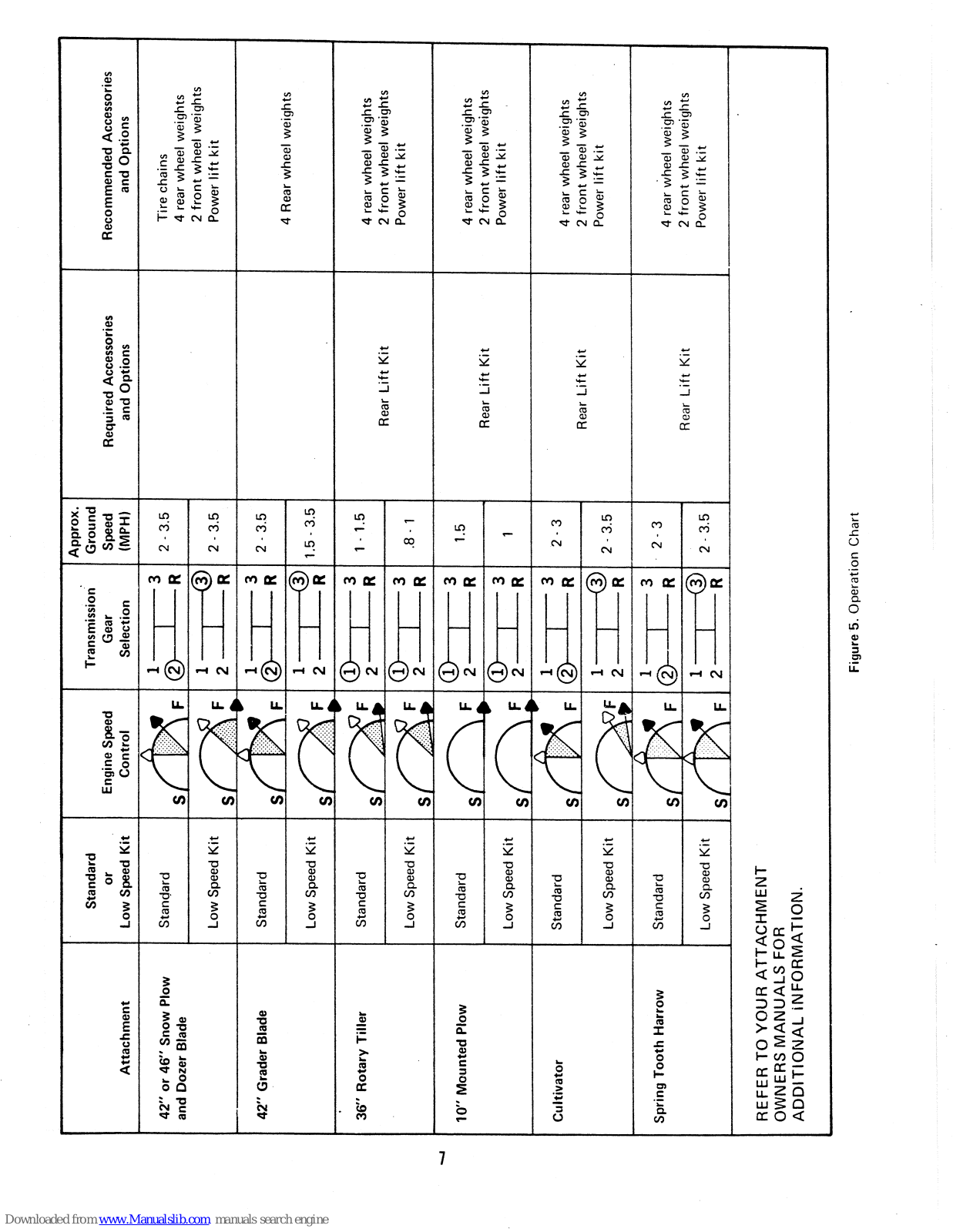
Standard Encirco Carood Transmission Approx.
Ground
Attachment or
Low Speed Kit
Engine Speed
Control
Gear
Selection
Speed
(MPH)
Required Accessories
and Options
Recommended Accessories
and Options
42" or 46" Snow Plow
and Dozer Blade
Standard S 2 - 3.5 Tire chains
4 rear wheel weights
Low Speed Kit SFF 13
2R
2 - 3.5 2 front wheel weights
Power lift kit
42" Grader Blade Standard S 2 - 3.5
Low Speed Kit S 1.5 - 3.5 4 hear wheel weights
36'' Rotary Tiller Standard S 1 - 1.5 Boor Lift Kit 4 rear wheel weights
2 front wheel weights
Low Speed Kit S .8 - 1 z nont wheel weights
Power lift kit
10" Mounted Plow Standard L S 2
2
R
R
1.5 4 rear wheel weights
Low Speed Kit S 2
- Hear Lift Kit z tront wheel weights
Power lift kit
Cultivator Standard S 2.3 • : \
• : \
• :
4 rear wheel weights
Low Speed Kit S 2 - 3.5 z iron wiee weignts
Power lift kit
Spring Tooth Harrow Standard S 2 - 3 4 rear wheel weights
Low Speed Kit S 2 - 3.5 Rear Lift Kit Z front wheel weights
Power lift kit
REFER TO YOUR ATT,
OWNERS MANUALS FC
ADDITIONAL INFORM
ACHMENT
JR
IATION.

7

Figure 5. Operation Chart

Page 10

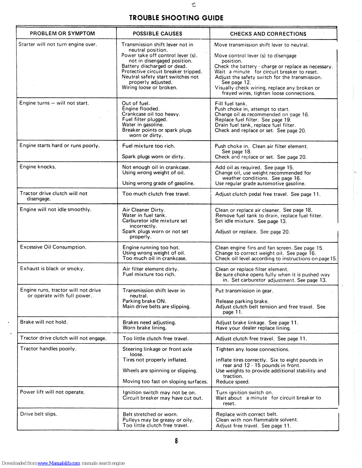
TROUBLE SHOOTING GUIDE

S.

PROBLEM OR SYMPTOM POSSIBLE CAUSES CHECKS AND CORRECTIONS
Starter will not turn engine over. Transmission shift lever not in
neutral position.
Power take off control lever (s).
not in disengaged position.
Battery discharged or dead.
Protective circuit breaker tripped.
Neutral safety start switches not
properly adjusted.
Wiring loose or broken.
  • Move transmission shift lever to neutral.
  • Move control lever (s) to disengage position.
  • Check the battery - charge or replace as necessary.
  • Wait a minute for circuit breaker to reset.
  • Adjust the safety switch for the transmission. See page 12.
  • Visually check wiring, replace any broken or frayed wires, tighten loose connections.
Engine turns – will not start. Out of fuel.
Engine flooded.
Crankcase oil too heavy.
Fuel filter plugged.
Water in gasoline.
Breaker points or spark plugs
worn or dirty.
Fill fuel tank.
Push choke in, attempt to start.
Change oil as recommended on page 16.
Replace fuel filter. See page 19.
Drain fuel tank, replace fuel filter.
Check and replace or set. See page 20.
Engine starts hard or runs poorly. Fuel mixture too rich.
Spark plugs worn or dirty.
Push choke in. Clean air filter element.
See page 18.
Check and replace or set. See page 20.
Engine knocks. Not enough oil in crankcase.
Using wrong weight of oil.
Using wrong grade of gasoline.
Add oil as required. See page 15.
Change oil, use weight recommended for
weather conditions. See page 16.
Use regular grade automotive gasoline.
Tractor drive clutch will not disengage. Too much clutch free travel. Adjust clutch pedal free travel. See page 11.
Engine will not idle smoothly. Air Cleaner Dirty.
Water in fuel tank.
Carburetor idle mixture set
incorrectly.
Spark plugs worn or not set
properly.
Clean or replace air cleaner. See page 18.
Remove fuel tank to drain, replace fuel filter.
Set idle mixture. See page 13.
Adjust or replace. See page 20.
Excessive Oil Consumption. Engine running too hot.
Using wrong weight of oil.
Too much oil in crankcase.
Clean engine fins and fan screen. See page 15.
Change to correct weight oil. See page 16.
Check oil level according to instructions on page 15.
Exhaust is black or smoky. Air filter element dirty.
Fuel mixture too rich.
Clean or replace filter element.
Be sure choke opens fully when it is pushed way
in. Set carburetor adjustment. See page 13.
Engine runs, tractor will not drive Transmission shift lever in Put transmission in gear.
or operate with full power. Parking brake ON.
Main drive belts are slipping.
Release parking brake.
Adjust clutch belt tension and free travel. See
page 11.
Brake will not hold. Brakes need adjusting.
Worn brake lining.
Adjust brake linkage. See page 11.
Have your dealer replace lining.
Tractor drive clutch will not engage. Too little clutch free travel. Adjust clutch free travel. See page 11.
Tractor handles poorly. Steering linkage or front axle
loose.
Tires not properly inflated.
Wheels are spinning or slipping.
Moving too fast on sloping surfaces.
Tighten any loose connections.
Inflate tires correctly. Six to eight pounds in
rear and 12 - 15 pounds in front.
Use weights to provide additional stability and
traction.
Reduce speed.
Power lift will not operate. Ignition switch may not be on.
Circuit breaker may have cut out.
Turn ignition switch on.
Wait about a minute for circuit breaker to
reset.
Drive belt slips. Belt stretched or worn.
Pulleys may be greasy or oily.
Too little clutch free travel.
Replace with correct belt.
Clean with non-flammable solvent.
Adjust free travel. See page 11.
Page 11

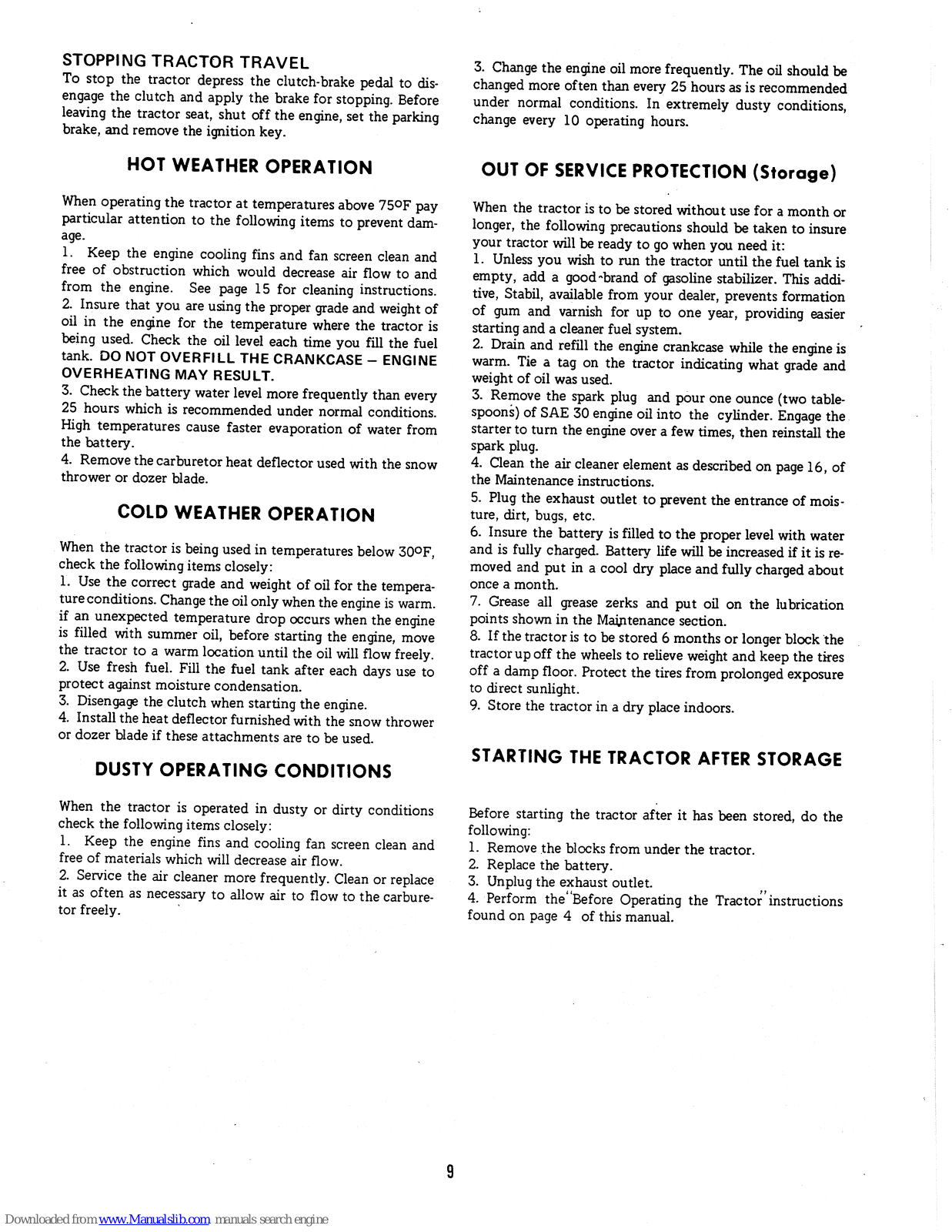
STOPPING TRACTOR TRAVEL

To stop the tractor depress the clutch-brake pedal to disengage the clutch and apply the brake for stopping. Before leaving the tractor seat, shut off the engine, set the parking brake, and remove the ignition key.

HOT WEATHER OPERATION

When operating the tractor at temperatures above 75°F pay particular attention to the following items to prevent damage.

1. Keep the engine cooling fins and fan screen clean and free of obstruction which would decrease air flow to and from the engine. See page 15 for cleaning instructions. 2. Insure that you are using the proper grade and weight of oil in the engine for the temperature where the tractor is being used. Check the oil level each time you fill the fuel tank. DO NOT OVERFILL THE CRANKCASE – ENGINE OVERHEATING MAY RESULT.

3. Check the battery water level more frequently than every 25 hours which is recommended under normal conditions. High temperatures cause faster evaporation of water from the battery.

4. Remove the carburetor heat deflector used with the snow thrower or dozer blade.

COLD WEATHER OPERATION

When the tractor is being used in temperatures below 30°F, check the following items closely:

Use the correct grade and weight of oil for the temperature conditions. Change the oil only when the engine is warm. if an unexpected temperature drop occurs when the engine is filled with summer oil, before starting the engine, move the tractor to a warm location until the oil will flow freely. Use fresh fuel. Fill the fuel tank after each days use to protect against moisture condensation.

3. Disengage the clutch when starting the engine.

4. Install the heat deflector furnished with the snow thrower or dozer blade if these attachments are to be used.

DUSTY OPERATING CONDITIONS

When the tractor is operated in dusty or dirty conditions check the following items closely:

1. Keep the engine fins and cooling fan screen clean and free of materials which will decrease air flow.

2. Service the air cleaner more frequently. Clean or replace it as often as necessary to allow air to flow to the carburetor freely.

3. Change the engine oil more frequently. The oil should be changed more often than every 25 hours as is recommended under normal conditions. In extremely dusty conditions, change every 10 operating hours.

OUT OF SERVICE PROTECTION (Storage)

When the tractor is to be stored without use for a month or longer, the following precautions should be taken to insure your tractor will be ready to go when you need it:

1. Unless you wish to run the tractor until the fuel tank is empty, add a good brand of gasoline stabilizer. This additive, Stabil, available from your dealer, prevents formation of gum and varnish for up to one year, providing easier starting and a cleaner fuel system.

2. Drain and refill the engine crankcase while the engine is warm. Tie a tag on the tractor indicating what grade and weight of oil was used.

3. Remove the spark plug and pour one ounce (two tablespoons) of SAE 30 engine oil into the cylinder. Engage the starter to turn the engine over a few times, then reinstall the spark plug.

4. Clean the air cleaner element as described on page 16, of the Maintenance instructions.

5. Plug the exhaust outlet to prevent the entrance of moisture, dirt, bugs, etc.

6. Insure the battery is filled to the proper level with water and is fully charged. Battery life will be increased if it is removed and put in a cool dry place and fully charged about once a month.

7. Grease all grease zerks and put oil on the lubrication points shown in the Maintenance section.

8. If the tractor is to be stored 6 months or longer block the tractor up off the wheels to relieve weight and keep the tires off a damp floor. Protect the tires from prolonged exposure to direct sunlight.

9. Store the tractor in a dry place indoors.

STARTING THE TRACTOR AFTER STORAGE

Before starting the tractor after it has been stored, do the following:

1. Remove the blocks from under the tractor.

2. Replace the battery.

3. Unplug the exhaust outlet.

4. Perform the 'Before Operating the Tractor" instructions found on page 4 of this manual.

Page 12

ADJUSTMENTS_

Most of the adjustments described here are easy to perform. Some of the adjustments require a little mechanical knowhow and some special tools to do them well. You may wish to have your dealer make some or all of the adjustments as they are required; however, we have given instructions for them here as convenience to you should you wish to make them yourself. CAUTION: DO NOT ATTEMPT TO MAKE ANY ADJUSTMENTS WHILE THE ENGINE IS RUN-NING UNLESS REQUIRED IN THE INSTRUCTIONS. IF THE ENGINE MUST BE RUNNING TO MAKE AN AD-JUSTMENT, BE CAREFUL TO STAY CLEAR OF ANY MOVING PARTS.

This tractor has been designed for easy accessibility to the areas which need to be reached in making adjustments and performing maintenance. The underside of the frame is open to provide easy access to areas requiring lubrication, adjustment, or repair.

RAISING THE TRACTOR HOOD

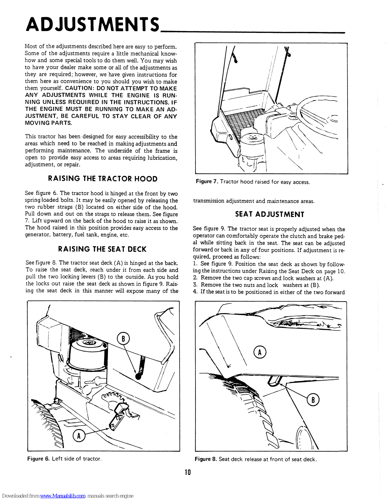
See figure 6. The tractor hood is hinged at the front by two spring loaded bolts. It may be easily opened by releasing the two rubber straps (B) located on either side of the hood. Pull down and out on the straps to release them. See figure 7. Lift upward on the back of the hood to raise it as shown. The hood raised in this position provides easy access to the generator, battery, fuel tank, engine, etc.

RAISING THE SEAT DECK

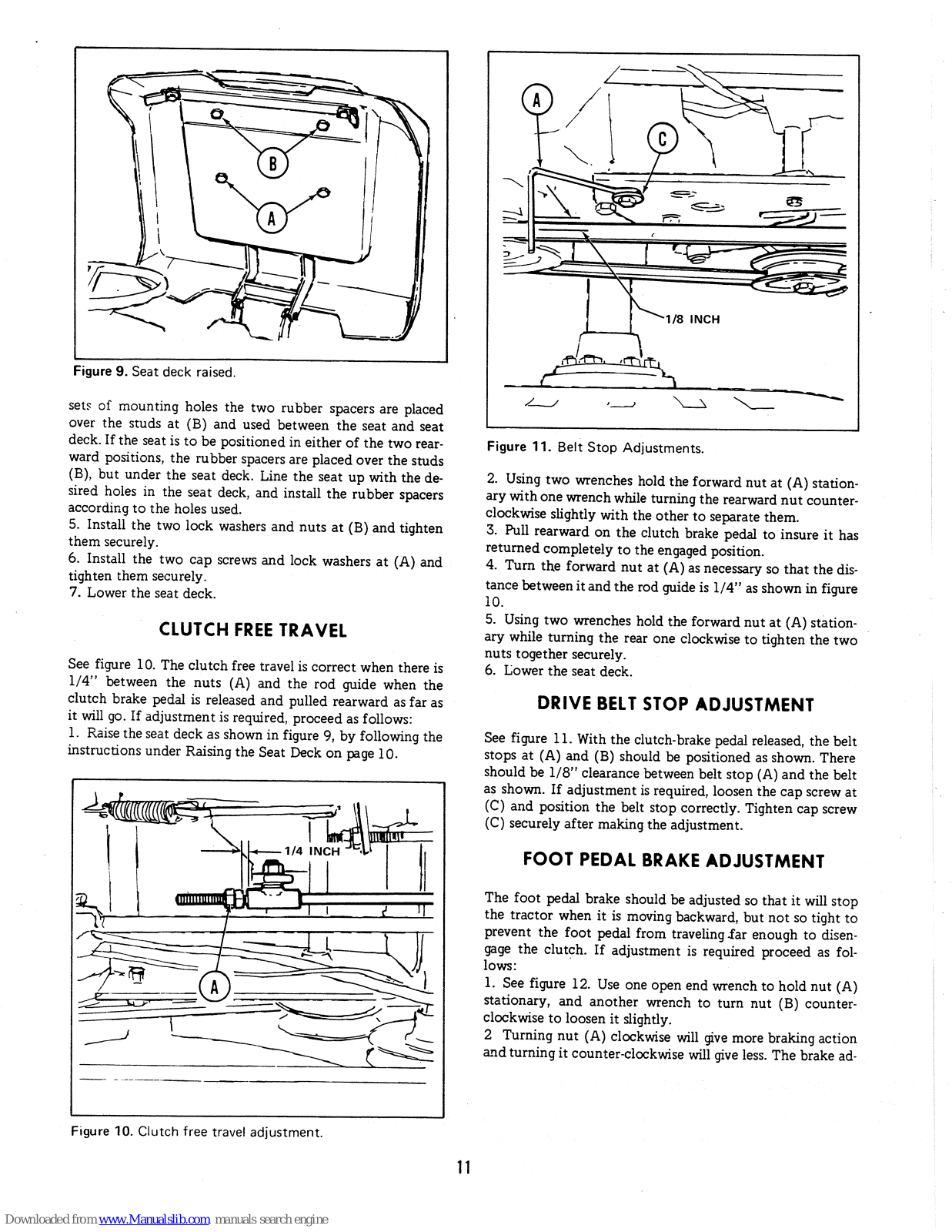
See figure 8. The tractor seat deck (A) is hinged at the back. To raise the seat deck, reach under it from each side and pull the two locking levers (B) to the outside. As you hold the locks out raise the seat deck as shown in figure 9. Raising the seat deck in this manner will expose many of the

Figure 6. Left side of tractor.

Figure 7. Tractor hood raised for easy access.

transmission adjustment and maintenance areas.

SEAT ADJUSTMENT

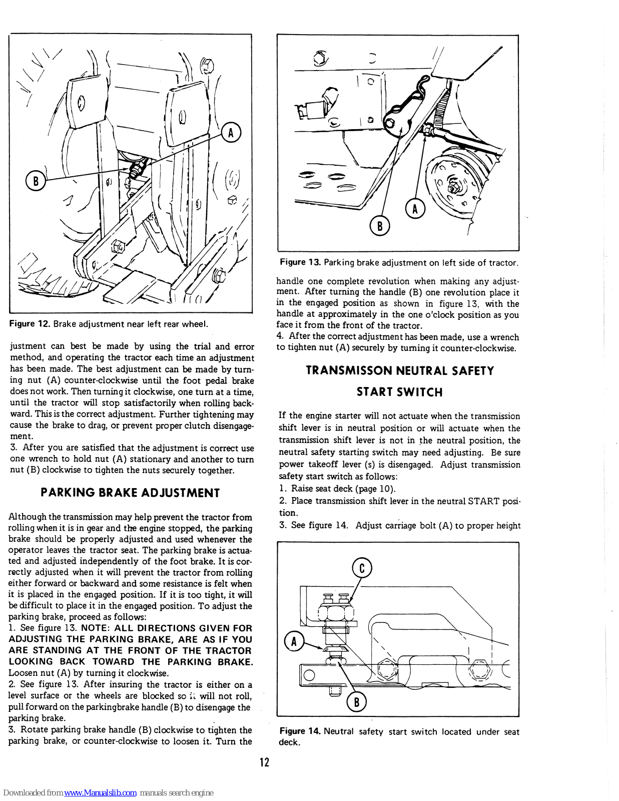
See figure 9. The tractor seat is properly adjusted when the operator can comfortably operate the clutch and brake pedal while sitting back in the seat. The seat can be adjusted forward or back in any of four positions. If adjustment is required, proceed as follows:

See figure 9. Position the seat deck as shown by following the instructions under Raising the Seat Deck on page 10. Remove the two cap screws and lock washers at (A).

  • 3. Remove the two nuts and lock washers at (B).
  • 4. If the seat is to be positioned in either of the two forward

Figure 8. Seat deck release at front of seat deck.

Page 13

Figure 9. Seat deck raised.

sets of mounting holes the two rubber spacers are placed over the studs at (B) and used between the seat and seat deck. If the seat is to be positioned in either of the two rearward positions, the rubber spacers are placed over the studs (B), but under the seat deck. Line the seat up with the desired holes in the seat deck, and install the rubber spacers according to the holes used.

5. Install the two lock washers and nuts at (B) and tighten them securely.

6. Install the two cap screws and lock washers at (A) and tighten them securely. 7. Lower the seat deck

Lower the seat deck.

CLUTCH FREE TRAVEL

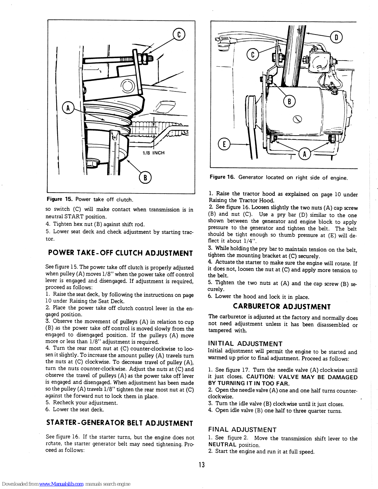
See figure 10. The clutch free travel is correct when there is 1/4" between the nuts (A) and the rod guide when the clutch brake pedal is released and pulled rearward as far as it will go. If adjustment is required, proceed as follows: 1. Raise the seat deck as shown in figure 9, by following the instructions under Raising the Seat Deck on page 10.

Figure 10. Clutch free travel adjustment.

Figure 11. Belt Stop Adjustments.

2. Using two wrenches hold the forward nut at (A) stationary with one wrench while turning the rearward nut counterclockwise slightly with the other to separate them.

3. Pull rearward on the clutch brake pedal to insure it has returned completely to the engaged position.

4. Turn the forward nut at (A) as necessary so that the distance between it and the rod guide is 1/4" as shown in figure 10.

5. Using two wrenches hold the forward nut at (A) stationary while turning the rear one clockwise to tighten the two nuts together securely.

6. Lower the seat deck.

DRIVE BELT STOP ADJUSTMENT

See figure 11. With the clutch-brake pedal released, the belt stops at (A) and (B) should be positioned as shown. There should be 1/8" clearance between belt stop (A) and the belt as shown. If adjustment is required, loosen the cap screw at (C) and position the belt stop correctly. Tighten cap screw (C) securely after making the adjustment.

FOOT PEDAL BRAKE ADJUSTMENT

The foot pedal brake should be adjusted so that it will stop the tractor when it is moving backward, but not so tight to prevent the foot pedal from traveling far enough to disengage the clutch. If adjustment is required proceed as follows:

1. See figure 12. Use one open end wrench to hold nut (A) stationary, and another wrench to turn nut (B) counterclockwise to loosen it slightly.

2 Turning nut (A) clockwise will give more braking action and turning it counter-clockwise will give less. The brake ad-

Page 14

Figure 12. Brake adjustment near left rear wheel.

justment can best be made by using the trial and error method, and operating the tractor each time an adjustment has been made. The best adjustment can be made by turning nut (A) counter-clockwise until the foot pedal brake does not work. Then turning it clockwise, one turn at a time, until the tractor will stop satisfactorily when rolling backward. This is the correct adjustment. Further tightening may cause the brake to drag, or prevent proper clutch disengagement.

3. After you are satisfied that the adjustment is correct use one wrench to hold nut (A) stationary and another to turn nut (B) clockwise to tighten the nuts securely together.

PARKING BRAKE ADJUSTMENT

Although the transmission may help prevent the tractor from rolling when it is in gear and the engine stopped, the parking brake should be properly adjusted and used whenever the operator leaves the tractor seat. The parking brake is actuated and adjusted independently of the foot brake. It is correctly adjusted when it will prevent the tractor from rolling either forward or backward and some resistance is felt when it is placed in the engaged position. If it is too tight, it will be difficult to place it in the engaged position. To adjust the parking brake, proceed as follows:

1. See figure 13. NOTE: ALL DIRECTIONS GIVEN FOR ADJUSTING THE PARKING BRAKE, ARE AS IF YOU ARE STANDING AT THE FRONT OF THE TRACTOR LOOKING BACK TOWARD THE PARKING BRAKE. Loosen nut (A) by turning it clockwise.

2. See figure 13. After insuring the tractor is either on a level surface or the wheels are blocked so it will not roll, pull forward on the parkingbrake handle (B) to disengage the parking brake.

3. Rotate parking brake handle (B) clockwise to tighten the parking brake, or counter-clockwise to loosen it. Turn the

Figure 13. Parking brake adjustment on left side of tractor.

handle one complete revolution when making any adjustment. After turning the handle (B) one revolution place it in the engaged position as shown in figure 13, with the handle at approximately in the one o'clock position as you face it from the front of the tractor.

4. After the correct adjustment has been made, use a wrench to tighten nut (A) securely by turning it counter-clockwise.

TRANSMISSON NEUTRAL SAFETY START SWITCH

If the engine starter will not actuate when the transmission shift lever is in neutral position or will actuate when the transmission shift lever is not in the neutral position, the neutral safety starting switch may need adjusting. Be sure power takeoff lever (s) is disengaged. Adjust transmission safety start switch as follows:

1. Raise seat deck (page 10).

2. Place transmission shift lever in the neutral START position.

3. See figure 14. Adjust carriage bolt (A) to proper height

Figure 14. Neutral safety start switch located under seat deck.

Page 15

Figure 15. Power take off clutch.

so switch (C) will make contact when transmission is in neutral START position.

4. Tighten hex nut (B) against shift rod.

5. Lower seat deck and check adjustment by starting tractor.

POWER TAKE-OFF CLUTCH ADJUSTMENT

See figure 15. The power take off clutch is properly adjusted when pulley (A) moves 1/8" when the power take off control lever is engaged and disengaged. If adjustment is required, proceed as follows:

1. Raise the seat deck, by following the instructions on page 10 under Raising the Seat Deck.

2. Place the power take off clutch control lever in the engaged position.

3. Observe the movement of pulleys (A) in relation to cup (B) as the power take off control is moved slowly from the engaged to disengaged position. If the pulleys (A) move more or less than 1/8" adjustment is required.

4. Turn the rear most nut at (C) counter-clockwise to loosen it slightly. To increase the amount pulley (A) travels turn the nuts at (C) clockwise. To decrease travel of pulley (A), turn the nuts counter-clockwise. Adjust the nuts at (C) and observe the travel of pulleys (A) as the power take off lever is engaged and disengaged. When adjustment has been made so the pulley (A) travels 1/8" tighten the rear most nut at (C) against the forward nut to lock them in place.

5. Recheck your adjustment.

6. Lower the seat deck.

STARTER-GENERATOR BELT ADJUSTMENT

See figure 16. If the starter turns, but the engine does not rotate, the starter generator belt may need tightening. Proceed as follows:

Figure 16. Generator located on right side of engine.

1. Raise the tractor hood as explained on page 10 under Raising the Tractor Hood.

2. See figure 16. Loosen slightly the two nuts (A) cap screw (B) and nut (C). Use a pry bar (D) similar to the one shown between the generator and engine block to apply pressure to the generator and tighten the belt. The belt should be tight enough so thumb pressure at (E) will deflect it about 1/4".

3. While holding the pry bar to maintain tension on the belt, tighten the mounting bracket at (C) securely.

4. Actuate the starter to make sure the engine will rotate. If it does not, loosen the nut at (C) and apply more tension to the belt.

5. Tighten the two nuts at (A) and the cap screw (B) securely.

6. Lower the hood and lock it in place.

CARBURETOR ADJUSTMENT

The carburetor is adjusted at the factory and normally does not need adjustment unless it has been disassembled or tampered with.

INITIAL ADJUSTMENT

Initial adjustment will permit the engine to be started and warmed up prior to final adjustment. Proceed as follows:

1. See figure 17. Turn the needle valve (A) clockwise until it just closes. CAUTION: VALVE MAY BE DAMAGED BY TURNING IT IN TOO FAR.

2. Open the needle valve (A) one and one half turns counterclockwise.

3. Turn the idle valve (B) clockwise until it just closes.

4. Open idle valve (B) one half to three quarter turns.

FINAL ADJUSTMENT

1. See figure 2. Move the transmission shift lever to the NEUTRAL position.

2. Start the engine and run it at full speed.

Page 16

Figure 17. Carburetor adjustments.

3. See figure 17. Turn needle valve (A) clockwise until engine misses, (Lean mixture), then turn it out counter-clockwise past the smooth operating point, until the engine runs unevenly (Rich mixture). Now turn needle valve (A) to the mid-point between the rich and lean mixture so the engine runs smoothly.

4. Move the engine speed control lever to the slow position, and set the idle speed adjusting screw (C) so a fast idle is obtained (1200 RPM). Hold the throttle in this idle position and turn the idle valve (B) clockwise (lean) and counterclockwise (rich) until the engine idles smoothly.

5. Reset the idle speed so the engine idles at 1200 RPM. Push the engine speed control lever forward to the fast position, the engine should accelerate without hesitation or sputtering. If the engine does not accelerate properly, readjust needle valve (A) to a slightly richer mixture.

Page 17

MAINTENANCE

Your tractor has been designed and manufactured to give you many years of dependable operation. In order for it to give you efficient, trouble free service over a long period of time the maintenance operations listed here must be performed on a regular basis. The optional hour meter provides an accurate method of determining when these services need to be performed.

A wide variety of attachments and accessories permit use of your tractor throughout the year. BECAUSE YOUR TRAC-TOR IS A MULTI-SEASON TOOL, IT IS VERY IMPORT-ANT TO SERVICE THE ENGINE FOR THE SEASON IN WHICH IT WILL BE OPERATED. Be sure to change to winter grade oil before making cold weather starts.

Whenever you are checking fluid levels in any area of the tractor, the readings will be much more accurate if the tractor is setting on level ground. We have provided the Scheduled Maintenance Chart on page 18 as a convenient means for you to know which services should be performed at various times. You should, of course, refer to the detailed explanation of how to perform each maintenance task until you are familiar enough with it to perform it correctly from memory.

Refer to your Briggs & Stratton operating and maintenance instructions for more specific detail on servicing the engine.

ORDERING REPLACEMENT PARTS

Replacement parts required for performing maintenance services or repair work should be purchased from your dealer. When ordering parts be prepared to give him the tractor and engine identification numbers. If you have not already recorded these numbers on the inside front cover of this manual, we suggest that you do so now for convenient future reference.

EVERY 5 HOURS OF OPERATION

INSPECT THE TRACTOR AND ENGINE: Make a general inspection of the tractor and engine looking for loose bolts, oil leaks, low tire pressures, etc. A few minutes spent correcting a small problem could prevent a costly breakdown later.

CHECK ENGINE CRANKCASE OIL LEVEL: See figure 18. If the engine has been running, allow a minute or two for the oil to drain down into the crankcase before checking the oil level. Proceed as follows:

1. See figure 18. Turn the engine oil filler cap-dipstick (A) counter-clockwise and lift it out.

2. Wipe the oil from the dipstick with a clean cloth.

3. Replace the filler cap-dipstick in the filler pipe and turn the cap clockwise finger tight.

4. Remove the filler cap-dipstick and check the oil level on the dipstick.

5. If the oil is below the full line (B) shown in figure 18, add enough oil to bring the oil level up to the full mark. Use the same grade and weight of oil which is already in the engine. DO NOT OVERFILL THE CRANKCASE.

6. Replace the filler cap-dipstick (A) and tighten it securely.

Figure 18. Checking the engine oil at right front of tractor.

EVERY 25 HOURS OF OPERATION

CLEAN ENGINE FINS AND SCREEN: See figure 19. The blower screen (A) must be kept relatively free of chaff, grass, etc., which would restrict the flow of cooling air to the engine. Material which collects can normally be removed with a brush after the engine is shut off. The screen may need to be cleaned more often when mowing dry grass.

Figure 19. Engine blower screen located at rear of engine as seen from beneath tractor.

Page 18

See figure 21. All grass and chaff should be removed from the engine fins (A). CAUTION: THE ENGINE FINS ARE VERY HOT AFTER THE ENGINE HAS BEEN OPER-ATED. DO NOT TOUCH THEM UNTIL THE ENGINE HAS BEEN ALLOWED TO COOL. NEVER SPRAY WATER ON A HOT ENGINE.

CHANGE ENGINE OIL: Every 25 hours or more often under dusty operating conditions, change the engine oil, using an oil with designation of SC or SD or MS.

(Abc

If no Use S

UMMER WINTER
ove 40°F.) (Under 40°F.)
SAE 30 Use SAE 5W-20 or
SAE 5W-30
t available, If not available,
AE 10W-30 Use SAE 10W or
or SAE 10W-30
E 10W-40
(Below 0 o F.)
Use SAE 10W or
SAE 10W-30
Diluted 10%
with Kerosene

1. Operate the engine at least 10 minutes or until it is warm so the oil will drain freely.

2. See figure 20. Remove the drain plug (A) from the bottom of the engine base and allow the oil to drain.

3. After the oil has been completely drained from the engine replace the drain plug and tighten it securely.

4. See figure 18. Remove the filler cap-dipstick (A) and pour 2 quarts of oil into the engine through the oil filler pipe, be-

Figure 20. Left front of tractor.

Figure 21. Air cleaner with cover removed on left side of engine.

ing careful not to allow any dirt or foreign material to contaminate the oil.

5. Check the oil level. It should show up to the full mark (B) on the dipstick.

6. Replace the oil filler cap-dipstick, start the engine and check for leaks.

CLEAN ENGINE AIR FILTER: The foam precleaner should be removed and cleaned at 3 month intervals or every 25 hours of operation, whichever occurs first.

1. See figure 20. Remove the wing nut (B) and cover (C) from the air cleaner unit.

2. See figure 21. Remove the foam precleaner (B) and wash it in liquid detergent and water and squeeze dry.

3. Oil the precleaner with one ounce of engine oil, and squeeze it to distribute the oil evenly.

4. Install the foam precleaner as shown in figure 21.

5. See figure 20. Replace the air cleaner cover (C) and fasten it securely with wing nut. (B).

Figure 22. Right front corner of tractor.

16

Page 19

Figure 23. Steering gear as seen from beneath tractor.

LUBRICATE GREASE FITTINGS: Your tractor has 6 grease fittings which should be lubricated every 25 hours with multi-purpose gun grease. Wipe the fittings clean and lubricate each one with five shots of grease, or until the grease is seen being forced from the bearing. When operating under extremely wet or dusty conditions, lubricate more often. The grease fittings are located as follows:

LOCATION ILLUSTRATIO
Left Spindle Figure 20, Item D
Right Spindle Figure 22, Item A
Clutch-brake Pedal Figure 22, Item B
Steering Bracket Figure 23, Item A
Right Axle Hub Figure 24, Item A
Right Axle Figure 25, Item A

LUBRICATE PIVOT POINTS: Every 25 hours a film of grease should be placed at the end of the neutral start safety switch and on the steering gear to provide smoother operation and help reduce wear. They are located as follows:

LOCATION ILLUSTRATION
Neutral Safety Start Switch Figure 14, Item C
Steering Gear Figure 23, Item B

A few drops of engine oil placed on the tractor pivot points will help reduce wear and provide smoother operation of the tractor and its controls. Every 25 hours or more often under wet or dusty operating conditions, place a few drops of SAE 30 engine oil on the pivot points, being careful not to get oil on belts or pulleys as it may cause them to slip. Pivot points are located as follows:

LOCATION ILLUSTRATION
Left Tie Rod End Figure 20, Item E
Right Tie Rod End Figure 22, Item C
Front Axle Pivot Figure 27, Item A
Power Take Off Pirot Figure 26 Item A

A CONTRACTION OF A CONT

Figure 24. Grease zerk on right rear axle hub.

CHECK TIRE PRESSURE: Tires will last longer and perform better if they are kept properly inflated. They should be inflated as follows; Front tires 12 to 15 PSI. Rear tires 6 - 8 PSI.

CHECK TRANSMISSION OIL LEVEL: See figure 28. Remove pipe plug (A) to check the oil level in the axle housing. Oil should be level with the bottom of the threads. If it is not, add SAE 90 weight transmission oil. Replace the plug and tighten it securely.

If it should be necessary to drain the axle housing, the drain plug is located at (B). Always tighten it securely when replacing to prevent oil leakage.

Figure 25. Grease zerk on right rennew

17

Page 20

Figure 26. Power take off idler pulley, pivot points as seen from beneath tractor.

CHECK BEVEL GEAR BOX OIL LEVEL: See figure 29. The bevel gear box fill plug is located at (A). The gear box is properly filled when SAE 90 weight transmission oil is added until it touches the end of the fill plug dipstick assembly. Do not screw plug into housing when measuring for oil level. Drain bevel gear housing by removing drain plug (B). To prevent oil leakage, securely tighten both fill and drain plugs. The fill plug assembly is vented.

CHECK BATTERY WATER LEVEL: See figure 30. Every 25 hours, or more often when operating the tractor in temperatures above 72°F, remove the 6 battery caps (A)

Figure 27. Front of tractor showing axle pivot.

and check the water level in each cell. When the battery is in use, water evaporates from it. Never allow the water level in the battery to get below the top of the plates. Fill the battery to the marking ring (D) with distilled water as shown in figure 30. If distilled water is not available, clean tap water may be used.

EVERY 100 HOURS OR ONCE A YEAR

CLEAN OR REPLACE AIR FILTER ELEMENT: The engine air cleaner is made up of two types of filters. The foam filter (Figure 21, item B) and a dry filtering element. The foam element should be cleaned and oiled every 25 hours as explained under the Every 25 Hour Maintenance Services. Once a year or every 100 hours, whichever occurs first, the paper element should be removed and cleaned or

After After each cycle of indicated hours
Service Required Page 5 25 100
Inspect the tractor and engine 15
Check engine crankcase oil level 15 ٠
Clean engine fins and screen * 15
Change engine oil * (First change 5 Hours) 16
Clean engine air filter * 16
Lubricate grease fittings * 17 ٠
Check tire pressure 17
Check transmission oil level 17
Check bevel gear box oil level 18
Check battery water level * 18
Check or replace air filter element * 18
Replace fuel filter * 19
Repack front wheel bearings 19
Clean and reset spark plug 20
Clean Battery cables 20
SCHEDULED MAINTENANCE CHART

*More often under dusty and / or hot weather operating conditions.

See your Briggs and Stratton Instructions for more complete information on servicing the engine.

Page 21

replaced. Proceed as follows:

1. See figure 20. Remove wing nut (B) and cover (C) from the air cleaner.

2. See figure 21.. Remove the foam element (B) and clean and oil it as described in the Every 25 Hour Maintenance Service.

3. Remove wing nut (C) and remove the paper element from the air cleaner.

4. Clean the element by tapping it gently on a flat surface. If it is very dirty, replace the element or wash it in detergent, and water rinse until water remains clear. The element must be dried thoroughly before using.

5. See figure 21. Replace the paper element and wing nut (C) and tighten it securely.

6. Install the foam element (B) over the paper element as shown in figure 21.

Figure 29. Bevel gear housing located under seat deck.

Figure 30. Tractor battery visible when hood is raised.

7. See figure 20. Replace cover (C) and wing nut (B) and tighten securely.

REPLACE FUEL FILTER: See figure 20. Every 100 hours or more often under dirty field conditions, the fuel filter (F) should be replaced. CAUTION: DO NOT RE-MOVE THE FUEL FILTER WHEN THE ENGINE IS HOT, AS SPILLED GASOLINE MAY IGNITE. USE CARE WHEN REMOVING AND INSTALLING CLAMPS (G), NOT TO SPREAD THEM ANY MORE THAN NECESSARY AS THEY MAY TAKE A SET AND NOT HOLD THE HOSE TO THE FILTER PROPERLY.

In extremely dirty fuel conditions, the fuel filter may become filled with dirt and restrict fuel flow. The filter can be washed in solvent and blown out with compressed air and used.

REPACK FRONT WHEEL BEARINGS

Every 100 hours of operation or once a year, the front wheel bearings should be removed and repacked with grease. Proceed as follows:

1. Block or jack the front of the tractor so the wheel you are to work on is not supporting the tractor.

2. See figure 31. Remove the grease cup (A) by prying off with a screw driver.

3. Use an Allen wrench to loosen the set collar (B).

4. Remove the set collar (B), washer (E), outer bearing (C), wheel (D), and inner bearing (F). It is best to keep the two bearings separate so you can put them back in their original place. Wash the bearing shaft, bearings, and wheel housing with a suitable solvent and wipe dry. Inspect the seal of the inner wheel. Replace it if it is damaged. NOTE: IT IS EX-TREMELY IMPORTANT THAT THE BEARINGS AND GREASE THAT IS PACKED IN THEM BE KEPT CLEAN. 5. Using the palm of your hand, force a good quality wheel bearing grease into the bearings. Place a coating of grease on the seal where it turns in the hub.

6. See figure 31. Replace the inner bearing and slide the wheel on the axle.

Page 22

Figure 31. Left front spindle and axle assembly.

7. Replace the outer bearing, washer and set collar. Spin the wheel slowly and press in on the set collar to seat the bearing. Be sure the seal on the inside of the wheel is properly seated. Hold in on the set collar and tighten the Allen screw securely.

8. Replace the grease cup.

CLEAN AND REPLACE SPARK PLUG: See figure 32. Every 100 hours the spark plug should be removed, cleaned,

ACCESSORIES

There are many optional accessories available for your tractor through your dealer. They will make your tractor perform better, or easier to operate when using various attachments. For recommended accessories to use, when your tractor is to be operated with an attachment, see the Operation Chart on page 7. See your dealer if you wish to purchase any of the following:

BALL HITCH - REAR FRONT LIGHT KIT REAR LIGHT KIT HUB CAPS (Set of 4) WHEEL WEIGHTS - REAR WHEEL WEIGHTS - FRONT POWER LIFT KIT DUAL LIFT LEVER REAR LIFT KIT TIRE CHAINS HOUR METER

Figure 32. Setting spark plug gap.

and the gap reset at .030". When the spark plug is worn out, replace it with AC GC 46, Autolight A 71 or Champion J-8.

CAUTION: BLAST CLEANING OF SPARK PLUGS IN MACHINES THAT USE ABRASIVE GRIT IS NOT RE-COMMENDED. SPARK PLUGS SHOULD BE CLEANED BY SCRAPING OR WIRE BRUSHING, AND WASHING WITH A COMMERCIAL SOLVENT.

CLEAN BATTERY CABLES: See figure 30. Every 100 hours or once a year the battery cables (B) and (C) should be removed and cleaned. CAUTION: ALWAYS REMOVE THE NEGATIVE "GROUND CABLE" (C) FIRST AND REPLACE IT LAST. Clean the battery with soap and water to remove all dirt, oil, and corrosion from the battery surface. Do not allow foreign material or cleaning solution to get inside the battery. Clean the terminals and battery clamps with a wire brush. Replace and tighten securely. After tightening coat the terminals and clamps liberally with a coat of grease or vaseline to inhibit corrosion.

ATTACHMENTS

To make your tractor most useful to you, we manufacture a complete line of attachments for it. They are available through your dealer. Contact him if you wish to purchase any of the following:

42" ROTARY MOWER 46" SICKLE BAR MOWER VACUUM COLLECTOR CART COVER (High capacity) CART COVER (Low profile) ROVING NOZZLE FOR VACUUM COLLECTORS CART. DUMP 1000 POUND CAPACITY CART - DUMP 400 POUND CAPACITY 38" LAWN REVITALIZER (Thatcher, aerator) 36" ROTARY SNOW THROWER 46" SNOW PLOW AND DOZER BLADE 42" SNOW PLOW AND DOZER BLADE SNOW CAR 36" ROTARY TILLER & 10" TINE EXT. 10" PLOW CULTIVATOR SPRING TOOTH HARBOW 42" GRADER BLADE

SPECIFICATIONS SUBJECT TO CHANGE WITHOUT NOTICE
Page 23

Downloaded from www.Manualslib.com manuals search engine

Page 24

Page 25

ENGINE & DRIVE SHAFT

Ref.
No.
Part No. Qty. Description
1 1 ENGINE
2 173335 1 . PAD, Fuel Tank
3 106582 1 GASKET, Felt
4 172455 1 SCREW, Rec. Hd.,
3/8-16 x 1-5/16'' lg.
5 919360 3 CAPSCREW, Hex, 3/8-16,
× 1-1/2″ lg.
6 917378 4 WASHER, Plain, 3/8
7 917965 4 LOCKWASHER, 3/8
8 916950 4 NUT, full hex, 3/8-16
9 170456 1 MUFFLER, Exhaust
10 172195 1 ELBOW & NIPPLE ASSY.
11 154378 1 LOCKNUT
12 171880 1 STRAP, Muffler
13 172061 1 CLAMP, Muffler
14 171115 1 TANK, Fuel
15 171252 1 CAP, Fuel tank
16 173204 2 HOSE, Fuel
17 173206 1 FILTER, Fuel
18 154372 4 CLAMP, Fuel
19 171330 2 STRAP, Tank
20 172744 2 STRAP, Fuel tank
21 8161056 2 BEARING, Pivot black
22 919318 1 CAPSCREW, Hex, 5/16
18 × 5/8″ lg.
23 917356 | 1 LOCKWASHER, 5/16
24 917372 | 1 NUT, full hex, 5/16-18
25 157424 8 WASHER, Special
Ref.
No.
Part No. Otv. Description
26 173026 1 COUPLING
27 922130 2 CAPSCREW, Hex, 3/8-
16 x 2-1/4″ lg.
28 916965 2 LOCKWASHER, 3/8
29 172328 1 SHAFT ASSY., Drive
30 172677 4 CAPSCREW, Hex, 3/8-16
31 916965 4 LOCKWASHER, 3/8
32 916950 4 NUT, Hex, full, 3/8-16
33 173026 1 COUPLING
34 157424 8 WASHER, Special
35 172264 1 FLANGE, Drive shaft
36 157427 1 SHAFT, Key Drive
37 924624 i, 11 SETSCREW, 3/8-24 x
3/8'' lg.
38 172677 2 CAPSCREW, Hex, 3/8-16
x 1'' lg.
39 916965 2 LOCKWASHER, 3/8
40 * 171241 | 1 KEY
41 * 930544 1 SETSCREW, 5/16-18
1 X 3/8″ lg.
42* 921959 1 CAPSCREW, Hex, 1/4-20
x 5/8" lg.
43* 916964 1 LOCKWASHER, 1/4
44* 917377 1 WASHER, Plain, 1/4"
45* 157126 1 SPACER
46* 912978 2 CAPSCREW, Hex, 5/16-
18 x 2'' lg.
47* 917642 2 WASHER, Plain, 5/16
48* 916965 2 LOCKWASHER, 1/2

* Indicates 10 HP Tractor

Page 26

FRAME, HOOD, GRILL & INSTRUMENT PANEL

Page 27

FRAME, HOOD, GRILL & INSTRUMENT PANEL

Ref. No. Part No. Qty. Description Ref. No. Part No. Qty. Description
1 1650294 1 FRAME ASSEMBLY 39 917415 1 NUT, Hex, Full, # 10-32
2 918199 4 LOCKWASHER, 7/16" 40 157315 1 BRACKET, Throttle
3 154289 | 1 BUSHING 41 156116 1 WASHER
| 4 916608 4 CAPSCREW, Hex, 7/16" 42 925391 1 SCREW, Self Tapping,
-14 × 1-1/2″ lg. 1/4"-20 × 5/8" lg.
5 171271 1 FOOT REST, R.H. 43 122186 1 CLAMP
6 174662 | 1 BUSHING 44 907727 1 CAPSCREW, Hex, 1/4"-20
176628 1 FOOT REST, L.H. × 5/8'' lg.
8 923346 6 BOLT, Carriage 5/16"-18 45 916964 1 LOCKWASHER, 1/4"
× 3/4" lg. 46 917377 | 1 WASHER, Plain, 1/4"
9 91/356 6 LOCKWASHER, 5/16" 47 916622 1 NUT, Hex, Full, 1/4"-20
91/3/2 6 NUT, Hex, Full, 5/16"-18 48 1651170 1 HANDLE, Clutch
917397 2 CAPSCREW, Hex, 5/16-18 49 172038 1 КЛОВ
1 10 017050 × 3/4″ lg. 50 171848 1 STOP, Throttle
12 91/356 2 LOCKWASHER, 5/16" 51 158424 1 ATM, Throttle
13 920470 2 NUI, Tinnerman 52 159107 1 WASHER
14 1050420 53 930665 1 WASHER, Dish Type
15 928/03 8 NUT, Tinnerman 54 923428 1 NUT, Hex, Full, Lock,
10 930301 SCREW, Self Lapping 3/8"-16
17 165100 1 /# 14 × 3/4" lg. 55 930531 2 SCREW, Phillips Hd. #
10 167077 PANEL, Instrument 10-32 × 1/2" lg.
10 172000 56 171804 2 WASHER
20 026025 PLATE, Steering 57 930627 2 NUT, Center Lock,
20 920020 0 SCREW, Phillips, 1/4"-20 # 10-32
21 017967 6 58 917415 | 1 NUT, Hex, Full, # 10-32
22 916055 59 101025 1 WASHER
22 1651135 1 60 158611 1 BRACKET, Pulley Guard
100 (100 1 61 917867 1 NUT, Tinnerman
24 172935 1 62 927340 1 CAPSCREW, Hex, 1/4"-20
25 1651162 1 62 010055 x 3/4" Ig.
26 171804 2 WASHER 63 916955 WASHER, Plain, 3/16"
27 172742 2 WASHER 04
65
930562 CAPSCREW, # 14 x 1-1/4" lg.
28 922711 4 LOCKWASHER Shake 66 171559 ROD ASSEMBLY, Shifter
Shakeproof # 10 67 020570
29 916621 4 NUT Hex Full # 10-24 930370 18 × 1 1/2" In
30 8191047 2 SPRING 68 017356 1
31 919360 2 CAPSCREW Hex 3/8"-16 69 917330 1 NUT Hay Full 5/16 19
x 1-1/2" la 70 157020 1 GUDE ASSEMBLY SHIT
32 923428 2 NUT, Hex, Full, Lock 71 916622 NUT Hey Full 1/4" 20
1 3/8''-16 72 916964 1 100KWASHER 1/4"
33 171355 1 CONTROL, Throttle 73 921959 1 CAPSCREW Hay 1/4" 20
34 1650997 1 CONTROL, Choke 02.000 x 5/8" la
35 158475 1 CLIP, Bowden, Wire 74 171600 2 STRAP Hood
36 922711 1 LOCKWASHER, 75 917452 1 SCREW Bd Hd # 10-32
Shakeproof # 10 3.7.02 x 1/2" lo
37 158475 1 CLIP, Bowden, Wire A 1/2 ig.
38 922121 1 SCREW, Rd. Hd., # 10-30 1 1
x 3/8" lg. 1
Page 28

Page 29

FRONT WHEELS, AXLE AND STEERING

Description

WASHER, Plain, 3/8" LOCKWASHER, 3/8" NUT, full hex, 3/8-16 CAPSCREW, Hex, 3/8-16

x 1-1/4 " lg. AXLE ASSY., Front

WASHER, Plain, 1/2" CAPSCREW, Hex NUT, Toplo, 1/2"-13 WHEEL, Steering CAPSCREW; Hex, 5/16-18 x 1-1/4" lg. LOCKNUT, Flange, 5/16-18 CASTING, Steering

CASTING, w/ Bearings BEARING, Needle PLATE, Steering LOCKNUT, Full hex, 7/16-14 LOCKNUT, Hex iam.

CAPSCREW, Hex, 3/8-16,

BUSHING FITTING, Grease

SPACER

BUSHING

3/8-16

x 3/4" lg. PINION KEY

SHAFT, Steering RING, Retaining CAPSCREW, Hex, 3/8"-16 x 7/8" lg. SETSCREW, 5/16-18

ARM ASSY., Steering WASHER, Plain 7/16"

RING."E"

GEAR

SPACER

у.

Ref.
No.
Part No. Qty. Description Ref.
No.
Part No. Q
1 176376 2 WHEEL & TIRE 28 174177 2
ASSEMBLY 29 917378 2
1* 171483 2 WHEEL & TIRE 30 916965 5
ASSEMBLY 31 916950 2
2 157490 2 TIRE 32 917400 4
2* 153037 2 TIRE
3 164247 2 TUBE 33 157616 1
3* 153038 2 TUBE 34 154289 4
4 156305 2 STEM, Valve & Cap 35 914687 3
4* 171270 2 STEM, Valve & Cap 36 157618 1
5 171377 2 WHEEL, Sub Assy. 37 918431 2
5* 171484 2 WHEEL, Sub Assy. 38 927469 1
6 171378 2 WHEEL, Front 39 930648 1
6* 171485 2 WHEEL, Front 40 1606342 1
7 154393 4 CUP, Bearing 41 921977 1
8 154886 4 CONE, Bearing
9 154487 2 CAP, Hub 42 929001 1
10 170168 2 SEAL
11 171774 1 SPINDLE ASSEMBLY, 43 170960 1
L.H. 44 170992 1
12 157494 1 SPINDLE ASSEMBLY, 45 171832 1
R.H. 46 154258 2
13 922133 1 NUT, Hex jam, 1/2-13 47 171000 1
14 171375 4 SPACER 48 924058 1
15 8021010 3 COLLAR, Set
16 928734 2 SETSCREW, 5/16-18x
5/16 ''lg.
49 928731 2
17 8061012 1 WASHER 50 921965 1
18 108181 3 WASHER
19 157286 1 RING, Retaining 51 170988 1
20 170998 1 ARM ASSEMBLY, 52 910224 1
Steering L.H. 53 171020 1
21 157427 2 KEY 54 154264 1
22 928721 2 SETSCREW, 5/16-18
x 1/2" lg.
55 919357 2
23 171830 1 ROD, Tie 56 928691 1
24 9 19262 2 NUT, Jam, 1/2-20 57 1602155 1
25 164272 2 JOINT, Ball 58 170999 1
26 930633 2 LOCKNUT, Hex. jam 59 918430 1
27 157499 1 1/2"-20 60 170987 1
107,400 ۶. LINK ASST., Drag

* For 10 HP Three-Speed

27

Page 30

TRANSMISSION GROUP

Page 31

TRANSMISSION

F

Ref. No. Part No. Qty. Description
1 157516 1 GEAR CASE SUB-
ASSEMBLY
W/BEARINGS
(Includes 1 Thru 7)
2 918113 2 PIN, Roll
3 154257 | 1 BEARING, Needle
4 154258 1 BEARING, Needle
5 154259 2 BEARING, Needle
6 157519 1 BEARING, Needle
7 154538 1 ROLL PIN SUB-
ASSEMBLY
8 157619 2 SEAL, Oil
9 164250 | 1 ROD, Shift
10 172779 1 STEM, Shift
11 121084 2 SPACER
12 154067 1 SHAFT, Shifter
13 154068 1 SHAFT, Shifter, Hi-Lo
14 8061048 2 RING, Retaining
15 917231 2 SCREW, Set, 5/16"-18
x 1/2" lg.
16 154069 2 FORK, Shifter
17 154323 2 SPRING
18 154262 2 BALL, Shift, Lock
19 174338 1 SHAFT, Pulley
20 118134 1 RING, Retaining
21 154462 1 WASHER
22 108472 1 WASHER
23 172982 1 WASHER
24 172981 1 WASHER
25 154264 1 RING, Retaining
26 164294 . 1 KEY
27 154072 1 PINION ASSEMBLY, Rev
28 154075 1 PINION ASSEMBLY, I &
II
29 157290 1 SHAFT, 1st Intermediate
30 154263 1 SEAL, Oil
31 154078 1 GEAR, Driven, I
32 154354 1 KEY
33 154079 1 PINION, 1st Intermediate
34 154080 1 PINION, Driven, III
35 8061012 3 WASHER
36 154081 1 GEAR, Driven, II
37 154082 1 SPACER
38 154264 1 RING, Retaining
39 174228 1 PINION, Rev - IV
40 154087 1 GEAR, Rev.
41 154352 1 SPACER
42 154352 1 PIN ASSEMBLY, Rev.
43 930245 1 NUT, Hex, Full, Lock,
1/2"-20
lef. No . Part No. Qty. Description
44 154325 1 WASHER
45 154086 1 SHAFT, II Intermediate
46 172979 1 WASHER
47 172978 1 WASHER
48 154038 1 WASHER
49 154266 1 RING, Retaining
50 164062 1 PINION, II Intermediate
51 154267 1 KEY
52 154089 1 GEAR, II Intermediate
53 917400 1 CAPSCREW, Hex, 3/8-16
x l-1/4" lg.
54 154090 1 SPACER
55 154091 1 SHAFT, III Intermediate
56 172979 2 WASHER
57 172978 2 WASHER
58 154266 1 RING, Retaining
59 154092 1 PINION, III Intermediate
60 164051 1 GEAR, III Intermediate
61 910224 2 KEY
62 164222 1 TUBE & BUSHING
ASSEMBLY
63 912808 1 FITTING, Lub.
64 154095 1 GEAR, Drive
65 154096 2 KEY
66 172977 2 WASHER
67 154097 1 WASHER
68 154268 2 RING, Snap
69 154269 2 WASHER
70 154269 2 SEAL
71 164234 1 GASKET Gear Case
72 154098 1 SPACER
73 164226 1 COVER ASSEMBLY, Gear
Case W/Bearings
74 154257 1 BEARING Needle
75 154271 1 BEARING Needle
76 154259 1 BEARING Needle
77 154520 1 BEARING Needle
78 154537 1
79 901653 2
80 916431 14 CAPSCREW, Hex, 5/16"
81 917356 14 LOCKWASHER 5/16"
82 164251 1 SUPPORT Switch
83 172241 1 BOIT Carriage 5/16"-19
04 020101 x l'' lg.
04
05
920161 NU1, Hex, Jam, 5/16-18
85 901653 1 PLUG, Pipe
80 108202 1 BEARING, Ball
8/
00
164064 1 RING, Retaining
88 164224 2 BUSHING
89 901723 1 ELBOW, 90°
Page 32

30

Page 33

ELECTRICAL SYSTEM

Ref. No. Part No. Qty. Description Ref. No. Part No. Qty. Description
1 122236 1 MOTOR, Generator 26 171811 1 CABLE, Battery to
2 122213 1 CABLE, Generator to Ground
1 Solenoid 27 925003 1 SCREW, Hex Washer Hd
3 157524 1 BELT, "V" 1/4"-20 x 1/2" lg
4 157654 1 SUPPORT ASSEMBLY 28 172119 1 INSULATION, Fuel Tan
5 917356 2 LOCKWASHER, 5/16" 29 178280 1 SWITCH, Ignition
6 917397 2 CAPSCREW, Hex, 5/16-18 30 122203 - 1 KEY & RING ASSEMBL
x 3/4" lg. 31 918906 1 LOCKWASHER, Int. 5/8
7 917356 2 LOCKWASHER, 5/16" 32 122234 1 NUT, Hex, Special
8 917372 2 NUT, Hex, Full, 5/16"-18 33 176912 2 CLIP, Wire
9 907729 2 CAPSCREW, Hex, 5/16"- 34 1651104 1 HARNESS ASSEMBLY
18 × 1-1/4'' 35 1651031 1 WIRE ASSEMBLY
10 122193 1 REGULATOR, Voltage 36 172175 1 GROMMET
| 11 1651128 1 BOARD, Terminal 37 106786 1 CLAMP
12 106132 3 SPACER 38 172163 1 BREAKER, Circuit
| 13 176931 1 BRACKET 39 171225 1 CLAMP, Battery
14 157102 1 ARM, Adjusting, 40 177522 1 SWITCH, Safety
Generator 41 930647 1 NUT, Pal, 9/16"-18
15 919316 3 CAPSCREW, Hex, 1/4"-20 42 122216 1 SOLENOID
x 1-3/4" lg. 43 925003 2 SCREW, Hex, Washer Hd.
16 921880 3 LOCKWASHER, 1/4''-20 x 1/2'' lq.
Shakeproof, 1/4'' 44 917415 1 NUT, Hex, Full, #10-32
17 916622 3 NUT, Hex, Full, 1/4"-20 45 922711 1 LOCKWASHER,
18 921332 1 CAPSCREW, Hex, 5/16"- Shakeproof, #10-32
18 × 3/4″ lg. 46 917372 2 NUT, Hex, Full, 5/16"-18
19 917642 | 1 WASHER, Plain 5/16" 47 177522 1 SWITCH, Safety
20 917356 2 LOCKWASHER, 5/16" 48 930647 1 NUT, Pal
21 917372 2 NUT, Hex, Full, 5/16"-18 49 917356 2 LOCKWASHER 5/16"
- 22 172270 1 BATTERY 50 916964 2 LOCKWASHER, 1/4"
23 1651103 1 CABLE, Battery 51 916622 2 NUT, Hex, Full, 1/4"-20
24 1603189 1 AMMETER
25 924433 2 NUT, Elastic, Stop,
5/16''-18
Page 34

CLUTCH AND BRAKE GROUP

Page 35
Ref. No. Part No. Qty. Description Ref. No. Part No. Qty. Description
1 174336 1 HUB, Pulley 36 174105 1 ROD ASSEMBLY, Brake
2 174356 1 PULLEY, Drive & Clutch
3 919319 3 CAPSCREW, Hex, 5/16" 37 917372 2 NUT, Hex, Full, 5/16-18
-18 x 7/8" lg. 38 121037 2 SPRING
4 917356 3 LOCKWASHER, 5/16" 39 157300 1 ARM, Pedal, Foot
5 905123 1 KEY 40 917378 1 WASHER, Plain, 3/8"
6 174364 | 1 "V" BELT 41 916950 1 LOCKWASHER, 3/8"
7 174359 1 PULLEY 42 916950 1 NUT, Hex, Full, 3/8-16
8 922133 2 NUT, Hex, Jam, 3/4''-16 43 108410 2 BUSHING
9 178557 1 GUIDE, Belt 44 171178 1 PEDAL ASSEMBLY, Foot
10 918199 1 LOCKWASHER, 7/16" 45 158196 2 WASHER, Special
11 905123 | 1 KEY 46 917378 1 WASHER, Plain, 3/8"
12 923329 1 NUT, Hex, Full, Lock, 47 172722 1 ROD, Brake
13 928745 1 1/4''-20
CAPSCREW Hex 1/4''-20
48 923362 1 NUT, Hex, Full, Lock,
5/16"-18
x 1-1/4" la 49 916950 1 NUT, Hex, Full, 3/8"-16
14 930666 1 LOCKWASHER Double 50 918213 2 NUT, Hex, Full, 7/16"-14
1/4" 51 157282 1 DRUM, Brake
15 174424 1 52 918199 1 LOCKWASHER, 7/16"
16 923347 1 BOLT Carriage 3/8"-16 53 171497 1 BAND ASSEMBLY, Brake
x 3/4" la 54 171482 1 BAND, Brake
17 916965 1 LOCKWASHER 3/8" 55 154133 1 LINING, Brake
18 916950 1 NUT, Hex, Full, 3/8"-16 56 927166 4 RIVET, # 7 x 5/16"
19 106707 1 STOP, Belt 57 164113 1 BRACKET, Brake Band
20 172108 1 LEVER, Brake, Parking 58 907731 2 CAPSCREW, Hex, 3/8"-16
21 917378 1 WASHER, Plain, 3/8" x 1″ lg.
22 916965 1 LOCKWASHER, 3/8" 59 916950 2 NUT, Hex, Full, 3/8''-16
23 907731 1 CAPSCREW, Hex, 3/8"-16 60 916965 2 LOCKWASHER, 3/8"
- x l‴lg. 61 916019 2 CAPSCREW, Hex, 1/4"-20
24 174497 1 PULLEY x 3/4″ lg.
25 919360 1 CAPSCREW, Hex, 3/8"-16 62 916964 2 LOCKWASHER, 1/4"
x 1-1/2″ lg. 63 916622 2 NUT, Hex, Full, 1/4"-20
26 917378 2 WASHER, Plain, 3/8" 64 174896 1 SPRING
27 916965 1 LOCKWASHER, 3/8" 65 174893 1 CLIP, Spring
28 916950 1 NUT, Hex, Full, 3/8"-16 66 917372 1 NUT, Hex, Full, 5/16"-18
29 173861 1 LEVER ASSEMBLY, Idler 67 171994 1 ROD, End
30 1602155 1 "E" RING 68 923422 1 NUT, Hex, Full, Lock,
31 164088 1 LINK, Clutch 5/16"-18
32 918447 3 PIN, Cotter 69 916432 1 CAPSCREW, 7/16"-14
33 172724 1 LEVER ASSEMBLY, Pivot x 1-1/4″ lg.
34 164094 1 GUIDE ASSEMBLY, Rod 70 174708 1 ROD ASSEMBLY
35 923362 1 NUT, Hex, Full, Lock,
5/16-18
Page 36

Page 37

REAR LIFT AND DRAW BAR

Ref. No. Part No. Qty. Description Ref. No. Part No. Qty. Description
1 171599 1 QUADRANT, Lift Lever 30 918390 1 . PIN, Roll, 3/8'' x 1-1/4'' la
2 170975 1 BEARING, Lift Lever 31 1651197 1 ROD, Latch
| 3 921977 1 CAPSCREW, Hex, 5/16"- 33 917642 2 WASHER, Plain, 3/8"
18 x 1-1/4'' lg. 34 1650155 1 SPRING
4 917356 1 LOCKWASHER, 5/16" 35 1650157 1 BUTTON, Thumb
5 917372 1 NUT, Hex, Full, 5/16''-18 36 156209 1 GRIP, Handle
6 170975 1 BEARING, Lift Lever 37 153058 1 PIN
7 921977 1 CAPSCREW, Hex, 5/16-18 38 8161045 1 CLIP. Spring
x 1-1/4'' lg. 39 157625 1 LEVER ASSEMBLY
8 917356 1 LOCKWASHER, 5/16'' - Front Lift
9 917372 1 NUT, Hex, Full, 5/16"-18 40 171593 1 SCREW Set 5/16"-18 x
10 908127 2 CAPSCREW, Hex, 3/8"-16 1/4″ Ig
x 3/4″ lg. 41 174085 1 CABLE ASSEMBLY Lift
11 916965 2 LOCKWASHER, 3/8" 42 172725 1 PULLEY
12 916950 2 NUT, Hex, Full, 3/8"-16 43 157081 1 SPACER
13 174111 1 SHAFT ASSEMBLY, Lift 44 174723 2 GUARD, Cable
14 157624 2 COLLAR, Set 45 108418 1 SCREW
15 928709 2 SCREW, Set, 5/16"-18 46 928731 1 NUT, Hex, Jam, Lock, 3/8
x 3/8" lg. -16
16 916608 1 CAPSCREW, Hex. 7/16"- 47 174215 1 PIN
14 x 1-1/2" la. 48 916241 1 PIN . Cotter. 3/32" x 7/8"
17 916609 1 CAPSCREW, Hex. 7/16" - la.
-14 x 1-3/4" lq. 49 153058 1 PIN
18 918199 3 LOCKWASHER, 7/16" 50 8161045 1 CLIP. Spring
19 918213 2 NUT, Hex, Full, 7/16"-14 51 164304 1 ARMASSEMBLY
20 917642 4 WASHER, Plain, 5/16" 52 164284 1 ARM ASSEMBLY
21 157652 2 KEY 53 918199 4 LOCKWASHEB 7/16"
22 928734 1 SCREW, Set, 5/16''-18 x 54 918212 4 CAPSCREW 7/16"-14 x
1/4′′ lg. 1″ la
23 171589 1 LEVER ASSEMBLY, Lift 55 154202 1 DBAW BAB ASSEMBLY
24 916965 2 LOCKWASHER 3/8" 56 157091 1 BAR Pull
25 922763 2 CAPSCREW, Hex, 3/8"-16 57 1608759 SPACER
x 1" la. 58 919364 1 CAPSCREW 7/16"-14 x 2
26 157652 2 KEY · -1/4" lo
27 171593 1 LEVER ASSEMBLY, Lift 59 154203 1 BAB Draw
28 928734 1 SCREW, Set, 5/16"-18 · ·
x 1/4" lq.
29 173039 1 LATCH, Lift Lever

35

Downloaded from www.Manualslib.com manuals search engine

Page 38

Page 39

POWER TAKE-OFF

Ref. No. Part No. Qty. Description Ref. No. Part No. Qty. Description
1 1650264 1 GUIDE, Spring 24 174455 1 PIVOT ARM ASSEMBLY
2 172206 1 RING, Retaining 25 918459 1 PIN, Cotter, 3/16'' x
3 171772 1 SPRING 1-1/2″ lg.
4 1650254 1 BEARING ASSEMBLY 26 105306 1 PULLEY
5 1650304 1 PULLEY 27 917402 1 CAPSCREW, 3/8"-16
6 174862 1 CLUTCH PLATE x 2‴ lg.
ASSEMBLY 28 157081 1 SPACER
7 8061081 1 KEY 29 916965 1 LOCKWASHER, 3/8"
8 930644 1 NUT, Flange, Lock, 30 916950 1 NUT, Hex, Full, 3/8''-16
1/2''-13 31 917642 2 WASHER, Plain, 5/16"
9 172206 1 RING, Retaining 32 173982 1 PULLEY, Idler
10 173957 1 DISK, Brake 33 170289 1 STOP, Belt
11 920036 4 SCREW, Socket Hd, 34 170291 1 SPACER
1/4''-20 x 5/8'' lg. 35 917402 1 CAPSCREW, Hex, 3/8"-16
12 1650906 1 PIVOT ASSEMBLY × 2′′ lg.
13 174013 1 SUPPORT, Brake 36 172329 1 SPACER
Assembly 37 916965 1 LOCKWASHER, 3/8"
14 1651450 2 SCREW, Thread Forming 38 916950 1 NUT, Hex, Full, 3/8"-16
15 171371 2 BUSHING 39 917642 1 WASHER, Plain, 5/16"
16 173988 1 ROD, Control 40 157262 1 SPRING, Tension
17 175316 1 SPRING, Conical 41 164047 1 ROD, Spring Tension
18 917372 2 NUT, Hex, Full, 5/16''-18 42 164155 1 HANDLE ASSEMBLY
19 173991 1 LEVER 43 157273 1 STUD
20 174686 | 1 CAPSCREW, Special, 44 924058 1 NUT, Hex, Full, Lock,
5/16''-16 x 7/8'' lg. 7/16′′-14
21 174664 | 1 HANDLE, Clutch pto 45 917397 1 CAPSCREW, Hex, 5/16"
22 172038 | 1 KNOB 18 x 3/4'' lg.
23 923428 | 1 NUT, Hex, Full, Lock, 46 923362 1 NUT, Hex, Full, Lock,
3/8′′-16 5/16''-18
· 47 1650252 1 GUIDE, Spring
Page 40

FRONT LIGHT GROUP OPTIONAL ON 10 HP 3-SPEED

Ref. No. Part No. Qty. Description Ref. No. Part No. Qty. Description
1 172286 1 SHROUD & PLATE
ASSEMBLY L H
12 928695 3 SCREW, Thread Forming
#12-24 x 1/2" Ig
2 172290 1 LAMP SOCKET & 13 172269 1 MOLDING
WIRE ASSEMBLY 14 172176 1 GROMMET
3 172048 2 HEADLIGHT 15 916019 4 SCREW, Hex, 1/4''-20 x
4 172243 1 PLATE, Front 3/4" Ig.
5 928695 3 SCREW, Thread Forming, 16 916964 4 LOCKWASHER, 1/4"
#12-24 × 1/2′′ lg. 17 172294 1 HARNESS ASSEMBLY
6 172269 1 MOLDING 18 1651821 1 WIRE, Headlight to
7 172176 1 GROMMET Ground
8 172285 1 SHROUD & PLATE 19 172296 1 WIRE ASSEMBLY,
ASSEMBLY R.H. Light Switch
9 172290 1 LAMP SOCKET & WIRE 20 1651147 1 WIRE ASSEMBLY
ASSEMBLY 21 122184 1 SWITCH, Toggle
10 172048 2 HEADLIGHT 22 178436 2 CABLE Clip, Tinnerman
11 172243 1 PLATE, Front 23 172434 1 CABLE Clip, Tinnerman
Page 41

* Indicates 10 H.P. tractor only

4-

Ref
No. Part No. Qty. Description
1 173432 2 WHEEL & TIRE
1* 173431 2 WHEEL & TIRE
ASSEMBLY
2 157637 2 TIRE
2* 157024 2 TIRE
3 157638 2 TUBE
3* 157602 2 TUBE
4 172353 2 STEM, Valve & Cap
5 173430 2 WHEEL, Drive
6 8261100 10 BOLT, Hub
7 928709 4 SCREW, Set, 5/16-18 x
3/8'' Lg.
8 154065 2 COLLAR, Set
9 105050 1 WASHER
10 177900 1 REAR AXLE ASSY.
11 121190 1 SEAL, Diff. Cover
12 176945 1 HUB ASSEMBLY
13 915019 1 FITTING, Grease
14 164217 | 1 CARRIER, Diff.
15 157120 2 KEY 39
Ref. Part No Otv Description
110.
16 171515 2 WASHER, Axle
17 153068 2 BEARING
18 171853 1 COVER, Diff.
19 177041 1 GEAR, Diff.
20 930671 2 KEY
21 154291 1 RING, Retaining
22 154277 1 WASHER, Axie
23 158579 8 PINION, Diff.
24 121083 8 SPINDLE, Pinion, Diff.
25 162085 8 SPRING
26 171517 2 RING, Spacer
27 171854 1 COVER, Diff.
28 921972 8 CAPSCREW, Hex, 3/8-18
x 2-1/2" lg.
29 923428 8 NUT, hex, full lock,
3/8′′-16
30 907727 6 CAPSCREW, Hex, 1/4-
20 x 5/8" lg.
31 916964 6 LOCKWASHER, 1/4"
32 916622 6 NUT, full, hex, 1/4-20

alslib.com manuals search eng

Page 42

Ref. No. Part No. Qty. Description
1 166111 1 DECK ASSEMBLY Seat
2 164029 1 BRACKET, Fit, Seat Deck
3 919318 2 CAPSCREW, Hex, 5/16"
18 x 5/8′′ lg.
4 917356 2 LOCKWASHER, 5/16"
5 917372 2 NUT, Hex, Full, 5/16"-18
6 157094 2 CONNECTOR, Cushion,
Frt.
. 7 1606823 2 CLIP, Seat Deck Latch
8 917356 4 LOCKWASHER, 5/16"
9 917377 2 WASHER, Plain, 1/4"
10 917372 4 NUT, Hex, Full, 5/16"-18
11 917400 2 CAPSCREW, Hex, 3/8"-16
x 1-1/4′′ lg.
Ref. No. Part No. Qty. Description
12 1607870 - 1 STOP, Seat Deck
13 923428 2 NUT, Hex, Full, Lock,
3/8''-16
14 917356 2 LOCKWASHER, 5/16''
15 917372 2 NUT, Hex, Full, 5/16''-18
16 171153 1 CONTOUR SEAT
ASSEMBLY
17 919318 2 CAPSCREW, Hex, 5/16-18
x 5/8" la.
18 917356 4 LOCKWASHER, 5/16''
19 159085 2 CONNECTOR, Cushion
20 917372 2 NUT, Hex, Full, 5/16''-18

Downloaded from www.Manualslib.com manuals search engine

Page 43

Ref. No. Part No. Qty. Description Ref. No. Part No. Qty. Description
1 171797 1 HOUSING, Gear, Bevel 22 154040 1 PLATE, Clamp, Bearing
2 178105 1 PLUG ASSEMBLY 23 917356 1 LOCKWASHER, 5/16"
3 173966 1 SHAFT, Driven 24 919318 1 CAPSCREW, Hex, 5/16-18
4 920677 4 CAPSCREW, Hex, 7/16-14 × 5/8′′ lg.
x 1-1/4'' lg. 25 172752 1 GEAR, Bevel, Driven
5 922133 1 NUT, Hex, Jam, 3/4''-16 26 905123 1 KEY
6 171792 1 SPACER 27 177649 2 WASHER
7 171790 5 SHIM (As Required) 28 154281 1 CAPSCREW, Hex
8 171791 1 SHIM 29 154282 | 1 GASKET
9 171787 1 SEAL, Oil 30 178104 1 COVER
10 172256 1 BEARING, Ball 31 901652 | 1 PLUG, Pipe
11 171796 1 GEAR, Bevel, Driven 32 920676 6 CAPSCREW, Hex, 7/16"
12 172206 1 RING, Retaining -14 x 1″ lg.
13 905123 1 KEY 33 920677 4 CAPSCREW, Hex, 7/16"
14 154279 1 BEARING, Needle -14 x 1-1/4″ lg.
15 118117 1 SEAL, Oil 34 930526 6 CAPSCREW, Hex, 1/4"
16 172750 1 SHAFT, Driven -20 x 5/8'' lg.
17 118117 1 SEAL, Oil 35 175127 1 PLATE ASSEMBLY, Side,
18 154279 1 BEARING, Needle R.H.
19 172256 1 BEARING, Ball 36 174829 1 PLATE ASSEMBLY, Side,
20 172206 1 RING, Retaining L.H.
21 172753 1 WASHER 37 918199 10 LOCKWASHER, 7/16"

41

Page 44
MAJOR ATTACHMENTS
,
DESCRIPTION MFG. NO.
* 48" ROTARY MOWER 1690021
42" ROTARY MOWER 1690022
42" MOWER HITCH 1690082
36" ROTARY TILLER 1690039
TINE EXTENSTION 1690419
REAR LIFT KIT 1690045
VACUUM COLLECTOR 1690024
VAC. COLL. ADAPTORS:
48" MOWER
42" MOWER
1690026
1690027
ROVING NOZZLE 1690031
* 42" SNOW THROWER 1690032
36" SNOW THROWER 1690033
DUMP CART 1600236
DUMP CART COVER 1690395

* 16 H.P. TRACTOR ONLY

Page 45

Page 46

Page 47

Downloaded from www.Manualslib.com manuals search engine

Page 48

Loading...