

Page 1

Installation
Operating
Instructions
Owner’s Manual
DOMESTIC USE ONLY
Please read this document carefully before installing and/or using
your vacuum cleaning system.
Model : _______________ Serial Number : ________________________
MaintenanceTroubleshooting
Warranty
Information
Page 2

2
IMPORTANT SAFETY INSTRUCTIONS
When using an electrical appliance, basic precautions should always be followed,
including the following.
Read all instructions before using this appliance
WARNING – To reduce the risk of fire, electric shock, or injury:
1. Do not leave appliance when plugged in. Unplug from outlet when not in
use and before servicing.
2. Do not use outdoors or on wet surfaces.
3. Do not allow to be used as a toy. Close attention is necessary when used by
or near children.
4. Use only as described in this manual. Use only manufacturer’s
recommended attachments.
5. Do not use with damaged cord or plug. If appliance is not working as it
should, has been dropped, damaged, left outdoors, or dropped into water,
return it to a service center.
6. Do not pull or carry by cord, use cord as a handle, close a door on cord, or
pull cord around sharp edges or corners. Do not run appliance over cord.
Keep cord away from heated surfaces.
7. Do not unplug by pulling on cord. To unplug, grasp the plug, not the cord.
8. Do not handle plug or appliance with wet hands.
9. Do not put any objects into openings. Do not use with any opening blocked;
keep free of dust, lint, hair, and anything that may reduce air flow.
10. Keep hair, loose clothing, fingers, and all parts of body away from openings
and moving parts.
11. Do not pick up anything that is burning or smoking, such as cigarettes,
matches, or hot ashes.
12. Do not use without dust bag and/or filters in place.
13. Turn off all controls before unplugging.
14. Use extra care when cleaning on stairs.
15. Do not use to pick up flammable or combustible liquids such as gasoline or
use in areas where they may be present.
16. Connect to a properly grounded outlet only. See Grounding Instructions.
SAVE THESE INSTRUCTIONS
Page 3

Table of ConTenTs
Preface .................................................................................... 4
Schematic – Units without Bags ................................................. 5
Schematic – Units with Bags ...................................................... 5
Installation
Unit Installation ........................................................................ 6
Dos & Don’ts ............................................................................ 7
Mufer Installation - (CI100 and BF100 models) ........................ 10
Mufer installation - other models ............................................ 11
Electric Connections................................................................ 11
Grounding Instructions ............................................................ 12
Low Voltage Connections ......................................................... 13
Operating instruction
Hose Hook-up & Inlets............................................................. 14
Using the integrated inlet ........................................................ 15
Progressive Start .................................................................... 16
Automatic Stop ....................................................................... 16
LED indicator .......................................................................... 16
Information center .................................................................. 17
3
Operating instruction
Motor ..................................................................................... 17
Hi Flow Hepa Bag (B20, BF40, BF60 and BF100 models) ........... 18
Dirt Receptacle (C20, CI40, CI60 and CI100 models) ................ 19
Filters (C20, CI40, CI60 and CI100 models) .............................. 19
Carbon Dust Filter (BF40, BF60 and BF100 models) .................. 20
Troublehooting
General Information ................................................................ 21
Decrease in suction strength ................................................... 22
Vacuum will not start ............................................................... 24
Vacuum will not stop ............................................................... 25
Warranty Information
Limited Lifetime Warranty ........................................................ 26
Page 4
4
PrefaCe
Your new Simplicity central vacuum system was designed and manufactured in Blainville, Quebec, by the largest central vacuum cleaner
manufacturer in Canada, providing a high-quality, state-of-the-art product.
Our extensive network of qualified professionals ensures first quality
service near you. Contact us for the location of the Simplicity authorized
service center in your area.
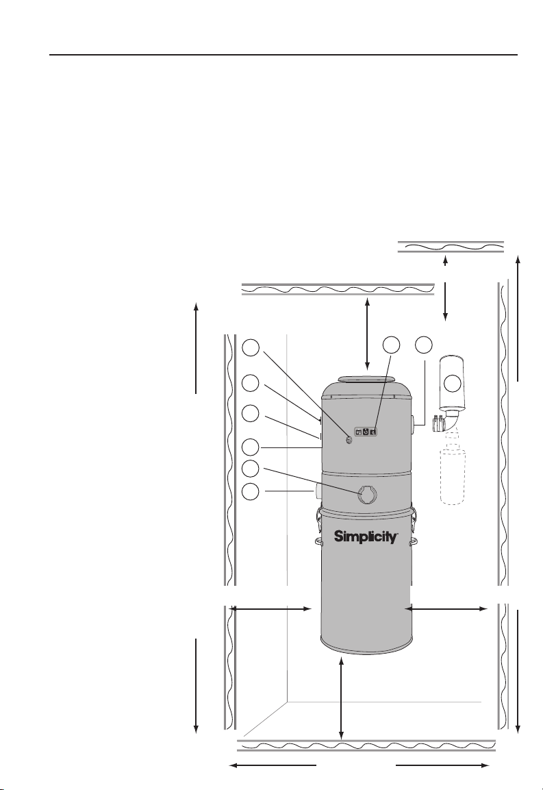
sChemaTiC – UniTs wiThoUT bags (C20, Ci40, Ci60 and Ci100 models)
1. Circuit Breaker
2. Low Voltage Connector
3. Serial Number
4. Integrated Inlet*
5. Air Intake
6. Integrated Switch*
7. Information center*
8. Air Exhaust
9. Muffler
* except C20 model
min. 30 cm (12")
If the muffler is turned down
6
1
2
3
4
5
min. 30 cm (12")
With mufer turned down 163 cm (64")
min. 30 cm (12")
7
8
9
min. 30 cm (12")
With mufer turned up 183 cm (72")
min. 30 cm (12")
Recommended 40 cm (16")
95 cm (38")
Page 5
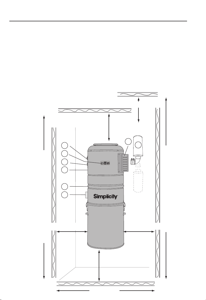
sChemaTiC – UniTs wiTh bags (b20, bf40, bf60 and bf100 models)
1. Circuit Breaker
2. Information center *
3. Low Voltage Connector
4. Serial Number
5. Upper Round Drum Filter (part #CF-B)
6. Air Intake
7. Carbon Dust Filter*
8. Muffler
* except B20 model
min. 30 cm (12")
min. 30 cm (12")
If the muffler is turned down
7
1
2
3
4
8
5
5
6
min. 30 cm (12")
With mufer turned down 163 cm (64")
min. 30 cm (12")
min. 30 cm (12")
Recommended 40 cm (16")
95 cm (38")
With mufer turned up 183 cm (72")
Page 6
6
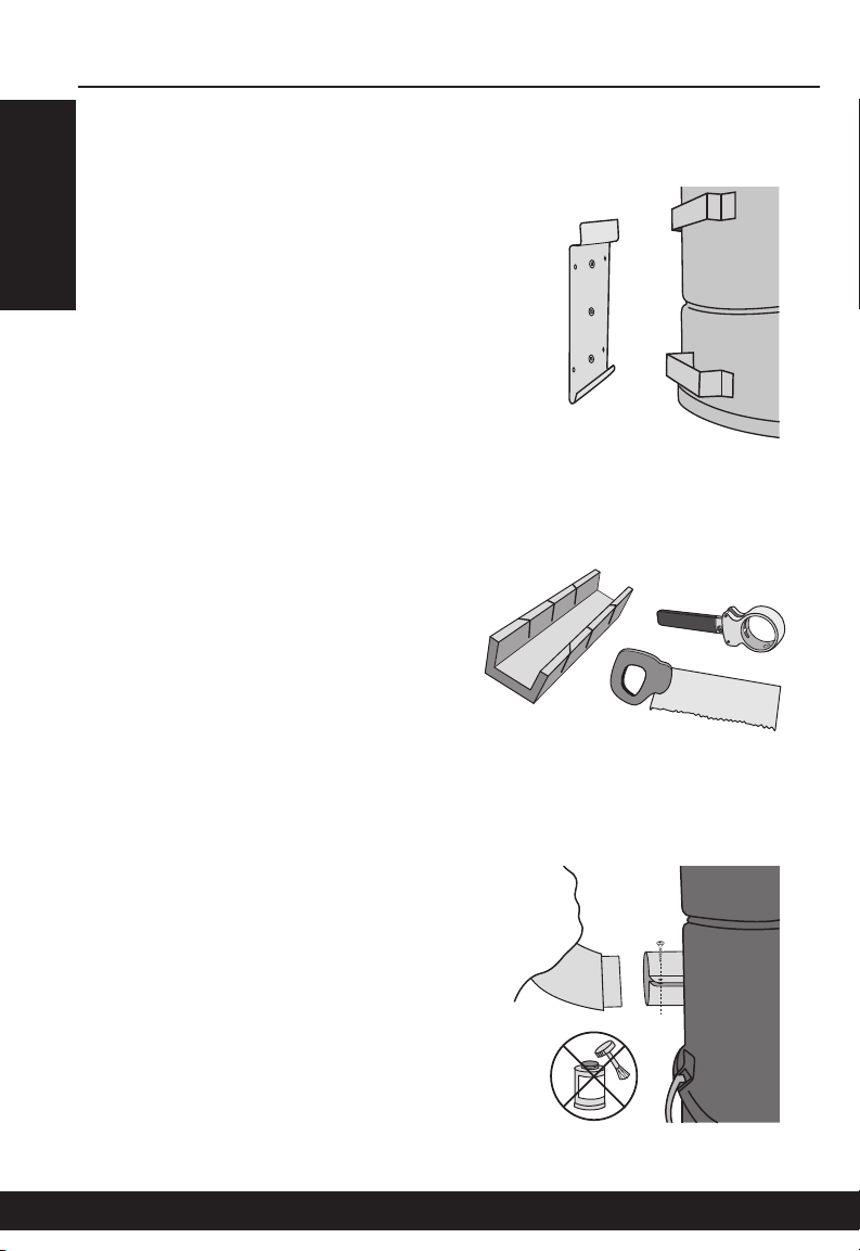
UniT insTallaTion
Using the mounting plate provided
with your vacuum cleaner, secure
the unit to the wall (gure 1), at
a height allowing easy access
for maintenance of the filters,
dirt receptacle and/or bags (see
pages 6 and 7).
The connections to the piping
system will require some basic
tools: a mitre box and small saw
or a pipe cutter (gure 2). See
pages 9 and 10 for general instructions pertaining to the preparation
of PVC pipes. To simplify matters,
installation kits, including necessary fittings, pipes, glue and wiring,
as well as a detailed instructions
booklet, are available from
Simplicity service centers.
gure 1
gure 2
Contrary to all other connections
in the piping system, do not glue
the last tting to your unit. Simplicity
central vacuums are equipped
with an adjustable air intake valve
(gure 3), which does not require
glue. An air-tight fit is achieved with
the screw-type adjustment on the
fitting itself.
Installation
gure 3
Page 7
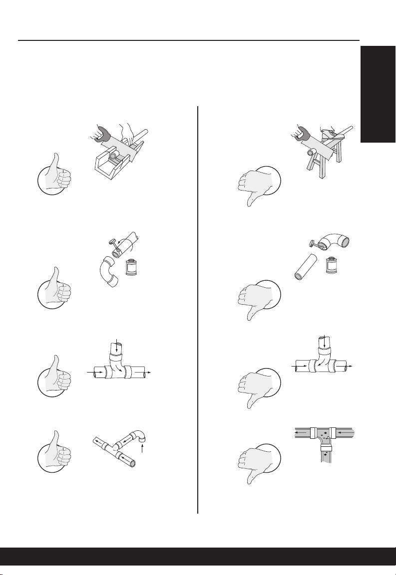
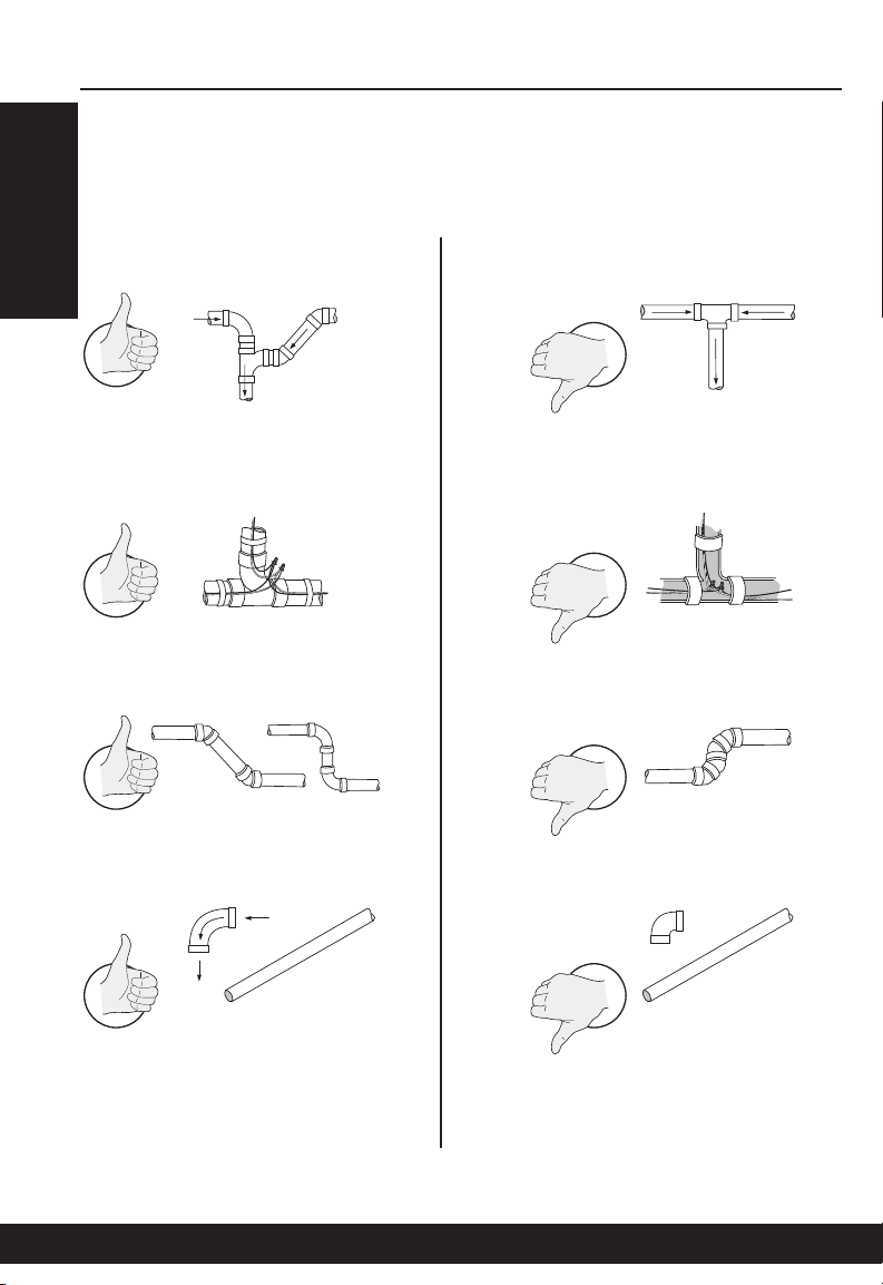
dos & don’Ts
Installing Conduits
7
Installation
Page 8
8
dos & don’Ts
Installing Conduits
Installation
Page 9
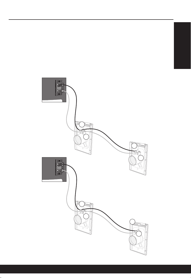
dos & don’Ts
Installing Inlets
When installing your vacuum inlets, we recommend that the principle of
electric polarity be taken into account. Ensure that the wire connected
onto contact A on inlet 1 is the same as that connected to contact A on
inlet 2, and so on. Do not cross, reverse or interchange wires.
A
B
A
9
Inlet 1
A
B
Inlet 1
Installation
B
Inlet 2
A
B
Inlet 2
Page 10

10
mUffler insTallaTion (oPTional)
BF100 and CI100 Models
1. Insert the rubber coupling on the vacuum air exhaust.
2. Using a screwdriver, tighten the clamp collars to ensure adequate sealing.
3. Insert the metal elbow into the rubber coupling, and tighten the clamp
collars as per instructions in step 2.
4. Apply metal glue to the metal pipe, and insert it into the 90°
elbow female end.
5. Slide the rubber sleeve on the metal pipe and
90° elbow, all the way to the rubber coupling.
6. Insert another rubber coupling onto the
metal pipe end (0.5 inch, under the sleeve),
and tighten the clamp collars.
7. Insert the male-male adaptor into
the rubber coupling, and tighten the
clamp collars.
8. Apply PVC glue to the visible part
of the male-male adaptor, and
insert the muffler.
* Must be vented outside.
To outdoors
36” • 91 cm
Glue not
included
PVC
Metal
Warning BF100 and CI100 Models
• Donotinstallinasmallenclosedplace
• Neverreduceairexhaustvolume.
• Eachmotorexhaustmustbeseparately
connected to metal conduits of at least
2 inches (5cm) in diameter for a length of
10 inches (25cm). Do not connect both
exhausts to the same conduit.
36” • 91 cm
PVC
To outdoors
Installation
Page 11

mUffler insTallaTion (oPTional)
OTHER MODELS
C
B
A
Glue not included
A
eleCTriC ConneCTions
There should be an electric outlet within 1 meter (3 feet) of your central
vacuum unit. Once the appliance is installed in a suitable location, connect your central unit to an electric outlet on an dedicated* grounded
circuit. Do not use extension cords or modify the length of your vacuum
cleaner’s power cord.
11
Dedicated* grounded circuit
• NorthAmerica
120 V / 240 V All models: 15A
Your central vacuum cleaner has a thermal safety device or a circuit breaker
to protect against any over voltage or electrical defect. If that protection
should fail, contact your authorized service center.
*Please reserve a circuit breaker dedicated only to the connections for your
central vacuum.
If you nd that installing your vacuum cleaner is too difcult, ask your service center to install it for you. When in doubt, it is better to have the work done by a professional and ensure that the unit is properly installed. Any installation that does not
comply with the specied norms could alter or invalidate the warranty.
Installation
Page 12

12
groUnding insTrUCTions
This appliance must be grounded. If it should malfunction or breakdown,
grounding provides a path of least resistance for electric current to
reduce the risk of electric shock. This appliance is equipped with a cord
having an equipment-grounding conductor and grounding plug. The
plug must be inserted into an appropriate outlet that is properly installed
and grounded in accordance with all local codes and ordinances. No
adaptor should be used with this appliance.
WARNING
Improper connection of the equipment-grounding conductor can result in
a risk of electric shock. Check with a qualified electrician or service person
if you are in doubt as to whether the outlet is properly grounded. Do not
modify the plug provided with the appliance – if it will not fit the outlet;
have a proper outlet installed by a qualified electrician.
120 V Models
This appliance is for use on a nominal 120 V circuit,
and has a grounded plug (gure 4). Make sure that
the appliance is connected to an outlet having the
same configuration as the plug. No adaptor should
be used with this appliance.
gure 4
220 V/240 V Models
(bf100 and Ci100 models only)
This appliance is for use on a circuit having a nominal
rating more than 120 V and is factory-equipped with a
specific cord and plug to permit connection to a proper
electric circuit. Make sure that the appliance is connected to an outlet having the same configuration as
the plug. No adaptor should be used with this appliance. If the appliance must be reconnected for use on
a different type of electric circuit, the reconnections
should be made by a qualified service personnel.
Installation
Page 13

low VolTage ConneCTions
Connect the low voltage wires to the low voltage inlet on your unit.
To do so:
1. Strip wires over 1 cm (1/2 inch) (gure 5).
2. Gently press on the toggle to open the connector (gure 6).
3. Insert stripped wire (gure 7).
4. Release toggle to secure wire in connector (gure 8).
5. Repeat for second wire.
To disconnect:
1. Gently press on the toggle to open the connector.
2. Remove low voltage wire from connector.
13
gure 6gure 5
gure 7 gure 8
Installation
LED - Models
C20 & B20 only
details on
page 16
Page 14

14
hose hook-UP & inleTs
Before operating your central vacuum…
Please verify that it is properly connected to the piping system, and to a
grounded electrical outlet, and that the low voltage wires are connected to
the unit (see pages 8 to 16). Then read the complete owner’s manual and
proceed with a quick verification of your unit’s installation:
• Checkfilterandbagtobesuretheyareproperlyinstalled.
• Checkrubbersealsineachvacuuminlet.
• Plugthehosealternativelyintoeachvacuuminlet,toensurethateach
one works properly.
• Whilethehoseisstillpluggedintooneinletandthesystemisoperational, check other inlets for leaks.
To start your central vacuum, simply insert the hose in the vacuum inlet of
your choice. Please ensure that the tab on the hose end is properly lined
up with the slot in the inlet opening (gure 7). If your hose handle has an
integrated on/off switch, simply slide the switch to the “on” position.
Do not try to open another inlet while your system is in operation, as it may
damage the inlet’s rubber seal.
gure 5
Operating Instructions
Page 15

Using The inTegraTed inleT
(Ci40, Ci60 and Ci100 models)
To use the vacuum inlet integrated into your central vacuum, simply
connect the hose and flip the integrated switch to the "on" position.
Please note that the integrated switch will start the power unit, even if
there is no hose connected to the inlet.
Caution : Your central vacuum must not be operated without a hose or when all
inlets are closed.This could cause irreversible damage to the power unit.
15
Operating Instructions
Page 16

16
ProgressiVe sTarT
(Ci40,Ci60, Ci100, bf40, bf60 and bf100 models)
Each model is equipped with a special module allowing for a smooth and
gradual start-up of the vacuum system, to prolong motor durability.
aUTomaTiC sToP
(Ci40, Ci60, Ci100, bf40, bf60 and bf100 models)
In case you’ve forgotten to turn off your vacuum, or it’s been turned on by
mistake, your vacuum system wil automatically shut off after one hour of
uninterrupted use. Simply restart the vacuum system with the switch on
the hose handle.
led indiCaTor
(C20, b20 models)
LED – On low voltage connector
Steady green – indicates unit is connected to a
power source
Operating Instructions
Page 17

17
informaTion CenTer
(Ci40, Ci60, Ci100, bf40, bf60 and bf100 models)
Your central vacuum unit is equipped with an electronic timing device
which will recommend proper maintenance of your vacuum system. These
signals are only suggestions and will do not indicate a problem with your
vacuum system. They will not stop or hinder the use of the vacuum.
Flashing LED - Empty dirt receptacle or change bag
Press to stop the flashing LED
Please note that the information/pictograms seen on the power unit information center are also available on the indicator hose handle (see details
below).
Flashing LED - Have unit checked by service center
moTor
Please note that Simplicity motors do not require lubrication. Each motor
contains two carbon brushes which will wear normally, and may eventually require replacement. For warranty purposes, this should be done by
an authorized service center. Brush life is affected by the number of hours
used, frequency of start-ups and shut-downs, humidity, altitude, and temperature. In order to avoid damage to the motor itself, brushes should be
replaced before they are completely worn out. We therefore recommend
that you have your unit and motors inspected by a service center every
5-6 years.
Maintenance
Page 18

18
hi flow hePa bag (b20, bf40, bf60 and bf100 models)
Change the bag when the one in place is full.
Frequency will depend on the use of the unit.
For models BF40, BF60 and BF100, the information center will indicate when to change
the bag. These indications are provided by an
electronic timing device, only as a reference
guide.
1. To access the bag, unlatch the two clips
and remove the dust receptacle (gure 8).
2. Remove the used bag and seal bag
opening (adhesive seal provided on each
bag). Discard used bag.
3. Install the new bag, ensuring the tabs on the
bag adaptor are aligned with the slots in the
bag collar (gure 9).
4. Ensure adequate sealing by inserting bag
as far as the retention ring.
gure 6
5. Replace dust receptacle and seal by
latching both clips.
Use only genuine Simplicity replacement bags.
Failure to do so could void the warranty on your
vacuum unit.
retention
UPPer roUnd drUm filTer
This drum-shaped filter requires no particular
maintenance. Should you want to replace this filter,
note that its part number is: #CF-B.
Maintenance
ring
gure 7
Page 19

dirT reCePTaCle (C20, Ci40, Ci60 and Ci100 models)
Occasional maintenance of the dirt receptacle is
necessary to ensure constant, lasting performance.
We recommend that it be emptied at least every
season, depending on frequency of use. For models
CI40, CI60 and CI100 the information center will indicate when to empty the canister. These indications
are provided by an eletronic timing device, only as a
reference guide.
To empty the dust receptacle, first disconnect your
vacuum cleaner from its power source. Then release
the two clamps, lower and empty the recipient, then
replace it and seal by refastening the metal clamps.
filTers (C20, Ci40, Ci60 and Ci100 models)
Your central vacuum system is equipped with a
Teflon* filter. This filter is designed to ensure high
performance and long term reliability of your vacuum
motor(s). It’s recommended to clean the filter when
emptying the dirt container.
To clean the filter, first remove the dirt container.
Next, remove the filter by grabbing the filter strap
and pulling the filter downward (gure 10). You may
shake the filter, wash the filter or replace the filter.
Before re-installing the filter, inspect it for tears or
punctures. If damaged or worn, replace with a new
filter. Do not re-install a damaged filter or one that is
still wet or damp.
Carefully install the filter in the support groove (gure
11) to ensure adequate protection of the motor(s).
Note: When washing the filter, wash in cold water
(no bleach) and dry at a low temperature. It is
important that the filter is completely dry before it is
re-installed.
19
gure 8
gure 9
*Teflon is a registered trademark of E.I.du Pont de Nemours company and is used under
license by APC Filtration, INC.
Maintenance
Page 20

20
Carbon dUsT filTer
(bf40, bf60 and bf100 models)
We recommend changing this filter after three
bag replacements. The integrated monitor
will indicate when to change the filter. These
indications are provided by an electronic timing
board, only as a reference guide.
To do so:
1. Unlatch the opening on the carbon filter
case and gently flip it upward (gure 12).
2. Remove the used filter, and discard
(gure 13).
3. Insert the new filter. When doing so, please
ensure that the arrow printed on the filter
itself points outwards (gure 14).
gure 12
4. Close casing, and latch.
gure 13
gure 14
Maintenance
Page 21

general informaTion
If the vacuum unit does not work, check the fuse or breaker on the unit
and/or in the electrical panel in your home, and replace any defective part (s) as deemed necessary. Please verify that the unit has been
installed properly, according to the instructions in this manual.
Your vacuum cleaning system is designed to collect everyday dry
matter (dust). It is approved by authorized testing agencies for dry
use only. Do not use on wet surfaces.
Should you accidentally vacuum liquids, immediately unplug the unit
from the electric outlet, then empty and wipe the dust recipient with
a dry cloth. Then operate the system from the vacuum inlet through
which you vacuumed the liquid, in order to eliminate all moisture in
the piping system.
We strongly recommend against vacuuming abrasive materials such
as cement, plaster and gyproc dust. This fine dust could work its
way into the motor, causing considerable damage. Should you do so
inadvertently, immediately clean the filters and, as a precautionary
measure, contact your authorized service center to determine the
extent of the damage to the unit.
21
Remember that in order for your warranty to remain valid, maintenance of
the motor and repairs to the unit itself must be carried out by an authorized
service center, using original Simplicity parts.
Troubleshooting
Page 22

22
TroUbleshooTing
Problem Possible cause Corrective action
Decrease in suction
strength
Dirt recipient / Bag is full Empty dirt recipient / change
bag (see page 17 to 18).
Dirt recipient is not properly attached
Open vacuum inlet Close all vacuum inlets not
Exhaust line is clogged Verify that no object is block-
Blocked hose Plug the handle end of the
Check clamps holding dirt
recipient, to make sure they
are tight, and dirt recipient is
aligned.
in use.
For bagless units also check
vacuum inlet on power unit
ing the exhaust.
hose into the suction inlet,
thus reversing the suction
in the hose. Cover the gap
around the handle, to ensure
suitable suction strength,
and ensure contact with inlet
contacts to start the unit.
This should clear the hose.
Troubleshooting
Page 23

TroUbleshooTing
Problem Possible cause Corrective action
23
Decrease in suction
strength (cont.)
If none of these suggestions restore suction strength, contact
Obstruction in the piping
system
Remove the screw from the
air intake connector, to free
the central vacuum unit from
the piping system (see figure
3 on page 6). Start the unit
by plugging the hose into
a vacuum inlet. By placing
your extended hand over
the air intake opening on
the unit, check the suction
strength on the unit itself. If
suction strength is normal,
the obstruction is in the
piping system. If suction
strength is diminished or
completely absent, have the
unit checked by an authorized service center.
your authorized service center.
Troubleshooting
Page 24

24
TroUbleshooTing
Problem Possible cause Corrective action
Vacuum will not start The electrical power is
not connected properly
Low voltage wire not
connected properly
Faulty vacuum inlet Start the vacuum unit from
Faulty switch Push the switch on the power
Unit circuit breaker
is off
Ensure that the power cord
is plugged into a dedicated
grounded electrical outlet,
according to specifications
on pages 11 and 12.
Verify the low voltage wires,
make sure they are properly
inserted into the low voltage
inlet, as per instructions on
page 13.
other inlets in your home, to
identify the defective inlet.
unit to the on position. If the
system starts, the problem
lies within the LV wiring.
Press the reset button to
reset the unit circuit breaker.
If unit restarts and automatically shuts off shortly after,
contact an authorized service center.
In-house circuit breaker
is off
Defective on/off hose Turn the hose 1/4 turn in the
Reset the circuit breaker in
your electrical panel. Verify
that your central vacuum unit
is connected on a dedicated
grounded circuit (see pages
11 and 12).
vacuum inlet. If unit starts,
have the vacuum hose
checked by a certified service center.
Troubleshooting
Page 25

TroUbleshooTing
Problem Possible cause Corrective action
25
Vacuum will not stop Hose improperly
inserted into vacuum
inlet
Defective on/off hose If the hose is properly placed
Low voltage wire not
connected properly
Ensure that the hose end is
properly placed in the
vacuum inlet: the tab on
the hose should fit into the
slots on the inlet, to ensure
adequate contacts for the
hose switch to function (see
page 14).
in the vacuum inlet, and
the unit continues running
despite the fact that the hose
switch is in the “off” position,
have the hose checked by a
service center.
While vacuum is on, unplug
low voltage wires from unit.
If vacuum stops, there’s a
faulty low voltage wire.
Contact your installer or
authorized service center.
Troubleshooting
Page 26

26
limiTed lifeTime warranTy
WHAT IS COVERED / HOW LONG COVERAGE LASTS:
All permanently installed components of a Simplicity central system are
warranted to be free of defects in material and workmanship under normal
use to the original purchaser at the original installation address. Motor and
electrical components are warranted for ten (10) years.
All Simplicity central system accessories are warranted to be free from
defects in material and workmanship under normal use for three (3) years
from the date of original consumer purchase.
In the event of a defect in permanently installed components of a
Simplicity central system, an authorized Simplicity retailer should be contacted. The retailer will repair or replace (at our option) any defective part
or parts at your location at no labor cost for a period of three (3) years.
Thereafter, repaired or replacement (at our option) part or parts will be
provided to you for items under warranty.
WHAT IS NOT COVERED:
•Damagetothecentralvacuumwhichoccursfromneglect,abuse,
alterations, accident, misuse or improper maintenance.
•Thiswarrantydoesnotextendtoanypowernozzleaccessorykitor
accessories used in conjunction with this power unit. Simplicity power
nozzle accessory kits are covered under a separate warranty.
WHAT SIMPLICITY WILL DO:
This warranty provides, at no cost to you, all labor and parts to keep this
central vacuum power unit in correct operating condition during the war-
ranted period.
Warranty Information
Page 27

27
HOW TO GET SERVICE:
Warranty service can only be obtained by contacting an Authorized
Simplicity Retailer. A proof-of-purchase and product serial number will
be required before service is rendered. To locate your nearest Simplicity
Retailer, please call 1-888-9SIMPLY or visit the Simplicity website
at www.simplicityvac.com.
THIS WARRANTY IS EXCLUSIVE AND IN LIEU OF ANY AND ALL OTHER
WARRANTIES WHETHER WRITTEN, ORAL, EXPRESSED OR IMPLIED,
(INCLUDING ANY WARRANTY OF MERCHANTABILITY OR FITNESS FOR
A PARTICULAR PURPOSE). THIS WAR-RANTY DISCLAIMS LIABILITY
FOR INCIDENTAL, OR CONSEQUENTIAL DAMAGES.
HOW STATE LAW APPLIES:
This warranty gives you specific legal rights, and you many also have
other rights which vary from state to state
Warranty Information
Page 28

 Loading...