

Page 1
Parts Manual
9
960 Large Frame
Two-Stage Snowthrowers
HP Snowthrowers
Mfg. No. Description
1694435 960M, 9HP Snowthrower (CE)
1694439 960E, 9HP Snowthrower
11/2003
Rev.
TP 400-3890-01-LW-S
Page 2

Page 3

Table Of Content
s
PRODUCT COMPONENTS PAGES
Handles and Controls Group .................................................................................................
Engine and Frame Group - 9HP Electric Start ......................................................................
Engine and Frame Group - 9HP Manual Start ......................................................................
Auger and Impeller Group - 24" .............................................................................................
Auger Housing and Chute Group - 24" ..................................................................................
Traction Drive Group .............................................................................................................
Wheels & Tires Group ..........................................................................................................
Decals Group - 960 ...............................................................................................................
Torque Specification Chart ..................................................................... Inside Back Cover
12
16
18
20
24
26
4
8
Page 4

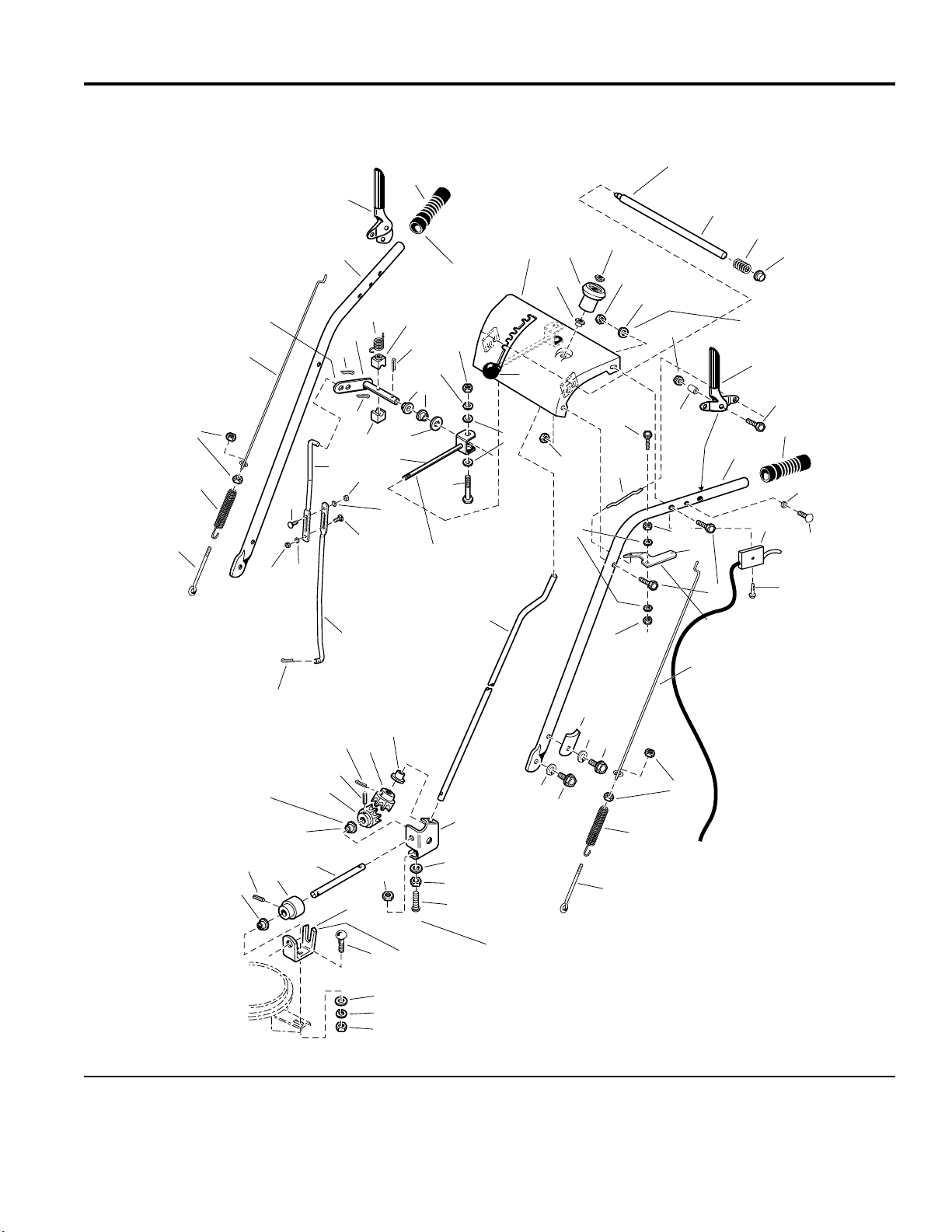
Handles and Controls Group
NOTE: Unless noted otherwise,
use the standard hardware torque
specification chart.
Insert shift rod (Ref. 55)
into outter hole of Ref. 61.
4
33
2
1
54
986366
Must slide freely in
7
6
10
5
Apply adhesive to
secure grips.
62
61
51
58
50
54
53
35
60
8
9
63
51
38
59
58
55
40
57
54
56
38
12
11
12
22
23
53
1624
40
Shift rod assembly (Ref. 57)
53
must pivot freely on
pivot blocks, (Ref. 58).
36
52
29
dash assembly (Ref 8).
Apply lubricant as required.
14
13
18
19
18
25
2028
Must pivot freely
on capscrew (Ref 22).
Apply lubricant as required.
4
15
16
Ref. 13 required on
slotted holes only.
17
20
7
21
64
65
26
27
51
9
50
49
Mount bushings (Ref. 9)
with flange on inside of
brackets, 3 places.
46
49
9
46
48
47
41
9
42
Slot towards
rear of unit.
43
38
39
40
44
31
45
The above parts group applies to the following Mfg. Nos.:
1694439 - 960E
1694435 - 960M
30
31
31
37
The holes in the frame for Ref. 40 are
slotted so the gear support (Ref. 37) can
be positioned to ensure the inside surface
of the gear support is tight against the
hub of the front gear (Ref. 49).
33
32
33
34
35
© Copyright Simplicity Manufacturing, Inc. All Rights Reserved.
2003
4
TP 400-3890-01-LW-S
Page 5

Handles and Controls Group
PART NO. DESCRIPTIONREF NO. QTY.
1 1668525 1 ROD, Auger, 3 7/16 Long 10-24
2 1669323 1 SPRING, Extension, 3 7/16 Long
3 1916621 4 NUT, Hex Machine Screw, 10-24
4 1715659 2 ROD, Clutch/Traction, 23 1/8 Long
5 1725434 1 HANDLE, RH
6 1722638 1 HANDLE, Clutch, RH
7 1725245 2 GRIP, Black Vinyl
8 1722627 1 DASHBOARD & SUPPORT ASSEMBLY
9 1667588 3 BUSHING, 3/8
10 1714084 1 KNOB, Spinner, 2 1/2 Long
11 1960093 1 PUSH NUT, Pal, 3/8
12 1919438 4 NUT, Hex Lock ESNA Light, 5/16-18
13 1919326 2 WASHER, 5/16
14 1722633 1 ROD & SPRING ASSEMBLY, with Pin
15 1722690 1 SPRING, Compression, 1 7/8 Long
16 1960519 1 PUSH NUT, Stud Cap, 1/2
17 1722667 1 HANDL E , Clutch, LH
18 1923358 2 NUT, Hex Centerlock, 1/4-20
19 1715655 2 SPACER
20 1922837 2 CAPSCREW, Hex Head, 1/4-20 x 1 1/2
21 1725433 1 HANDLE, LH
22 1960662 1 CAPSCREW Hex Head, 1/4-20 x 2
23 1722630 1 ROD, 5 3/4 Lo n g
24 1921319 2 WASHER, 1/4
25 1722631 1 LEVER, Pivot
26 1715654 2 SPACER
27 1960671 2 SCREW, Taptite, Pan Head, Torx, 1/4-20 x 3/4
28 1921221 4 CAPSCREW, Hex Head, 5/16 x 1 1/2
29 1920397 2 NUT, Hex Lock ESNA Light, 1/4-20
30 1720452 2 CLAMP, Tube Saddle
31 1917356 3 LOCKWASHER, Spring, 5/16
32 1922127 2 CAPSCREW, Hex Head, 5/16-18 x 1 3/4
33 1921332 2 CAPSCREW, Hex Head, 5/16-18 x 3/4
34 1707452 1 SPRING, Extension, Clutch Rod
35 1668526 1 ROD, Clutch, 6 5/16 Long
36 1715658 1 ROD, Chute Control, 27 Long
37 1718793 1 SUPPORT, Gear
38 1921319 3 WASHER, 1/4
39 1960518 2 PUSH NUT, 1/4
40 1960252 2 CARRIAGE BOLT, 1/4-20 x 5/8 G5
Footnotes
The above parts group applies to the following Mfg. Nos.:
1694439 - 960E
1694435 - 960M
© Copyright Simplicity Manufacturing, Inc. All Rights Reserved.
2003
5
TP 400-3890-01-LW-S
Page 6
Handles and Controls Group
NOTE: Unless noted otherwise,
use the standard hardware torque
specification chart.
Insert shift rod (Ref. 55)
into outter hole of Ref. 61.
4
33
2
1
54
986366
Must slide freely in
7
6
10
5
Apply adhesive to
secure grips.
62
61
51
58
50
54
53
35
60
8
9
63
51
38
59
58
55
40
57
54
56
38
12
11
12
22
23
53
1624
40
Shift rod assembly (Ref. 57)
53
must pivot freely on
pivot blocks, (Ref. 58).
36
52
29
dash assembly (Ref 8).
Apply lubricant as required.
14
13
18
19
18
25
2028
Must pivot freely
on capscrew (Ref 22).
Apply lubricant as required.
4
15
16
Ref. 13 required on
slotted holes only.
17
20
7
21
64
65
26
27
51
9
50
49
Mount bushings (Ref. 9)
with flange on inside of
brackets, 3 places.
46
49
9
46
48
47
41
9
42
Slot towards
rear of unit.
43
38
39
40
44
31
45
The above parts group applies to the following Mfg. Nos.:
1694439 - 960E
1694435 - 960M
30
31
31
37
The holes in the frame for Ref. 40 are
slotted so the gear support (Ref. 37) can
be positioned to ensure the inside surface
of the gear support is tight against the
hub of the front gear (Ref. 49).
33
32
33
34
35
© Copyright Simplicity Manufacturing, Inc. All Rights Reserved.
2003
6
TP 400-3890-01-LW-S
Page 7

Handles and Controls Group
PART NO. DESCRIPTIONREF NO. QTY.
41 1960294 1 NUT, Hex Whiz Lock Flange, Small, 1/4-20
42 1611911 1 SUPPORT, Worm
43 1931333 1 CARRIAGE BOLT, 5/16 x 3/4 G5
44 1919326 1 WASHER, 5/16
45 1917372 1 NUT, Hex, 5/16 -18
46 916168 2 PIN, Spring 1/8 x 3/4
47 1668186 1 WORM , Chute, LH
48 1725283 1 ROD, Chute, 18 Long
49 1718593 2 GEAR, Powder Metal
50 1918452 2 PIN, Cotter
51 1918447 3 PIN, Cotter
52 1666255 1 ROD, Shift, 3/8 15 5/16
53 1916964 3 LOCKWASHER, Spring, 1/4
54 1916622 3 NUT, Hex, 1/2-20
55 1720238 1 ROD, Upper Shift, 12 1/2 Long
56 1921159 1 CAPSCREW, Hex Head, 1/4-20 x 2 1/4 G5
57 1668523 1 ROD & CLEVIS ASSEMBLY, Shift
58 1668524 2 BLOCK, Pivot, 3/4 x 3/4
59 1924361 1 WASHER, 1/2
60 1668185 2 BUSHIN G, 1/2
61 1720240 1 ROD & ARM ASSEMBLY, Pivot
62 1715123 1 SPRING, Torsion, 1/2 Long
63 172038 1 KNOB
64 1718791 1 CABLE & HANDLE ASSEMBLY
65 1725702 1 SCREW, Pan Head, Torx, #10 x 1/2
Footnotes
The above parts group applies to the following Mfg. Nos.:
1694439 - 960E
1694435 - 960M
© Copyright Simplicity Manufacturing, Inc. All Rights Reserved.
2003
7
TP 400-3890-01-LW-S
Page 8
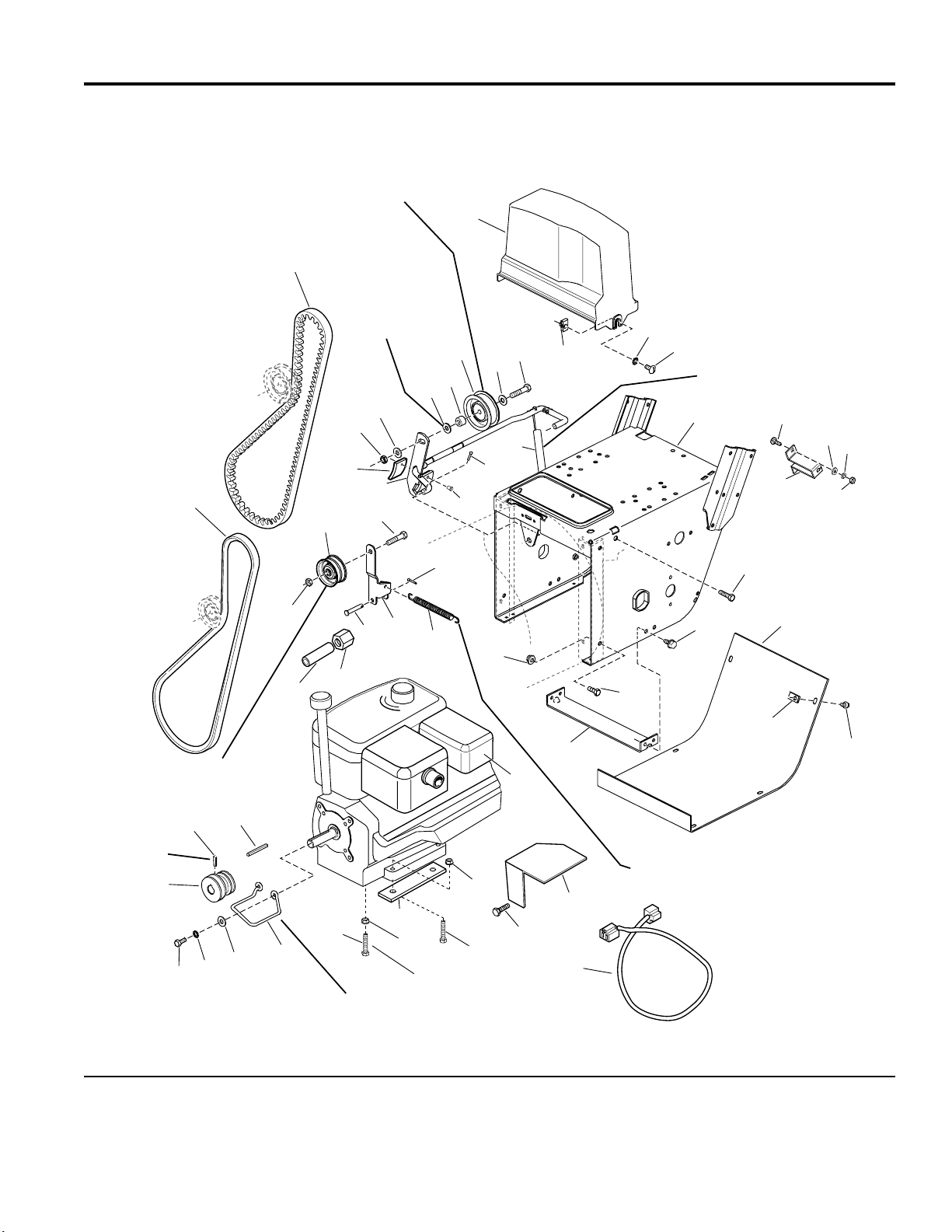
Engine and Frame Group - 9HP Electric Start
NOTE: Unless noted otherwise,
use the standard hardware torque
specification chart.
2
Position idler pulley (Ref. 25)
at center of slot in clutch arm
(Ref. 22).
1
Use 0-2 washers
between Ref. 40
& 22 to assure a
centered belt and no
interference between
pulleys Ref. 19 & 25.
39
18
18
23
22
19
20
39
40
25
3
24
39
21
27
26
986367
5
6
4
Hook one end of spring (Ref. 27)
over clutch rod assembly (Ref. 22)
between tabs and other end into
slot in frame.
7
44
45
50
46
47
Long hub of idler pulley
(Ref. 19) to be toward
idler arm (Ref. 16).
Torque to
10-14 ft. lbs. or
14-20 N m
36
35
37
34
18
48
38
33
32
Position belt stop (Ref. 33)
1/16 to 1/8 inch from belt
when auger clutch is engaged.
31
49
17
16
15
51
29
Right rear bolt.
21
30
29
14
28
43
13
41
42
8
9
10
8
11
Hook one end of spring (Ref. 15)
into top hole of roller arm (Ref. 16)
and other end into top hole of the idler
arm assembly in the Traction Drive Group.
12
The above parts group applies to the following Mfg. Nos.:
1694439 - 960E
© Copyright Simplicity Manufacturing, Inc. All Rights Reserved.
2003
8
TP 400-3890-01-LW-S
Page 9

Engine and Frame Group - 9HP Electric Start
PART NO. DESCRIPTIONREF NO. QTY.
1 1725416 1 BE L T , Tr action
2 1700415 1 BELT, Drive Auger
3 1725287 1 GUARD, Belt
4 1935255 2 NUT, Speed, 5/16-18
5 920426 2 L OCKWASHER , Ext. Tooth, 5/16
6 1918249 2 SCREW, Truss Head, 5/16-18 x 3/4
7 1725438 1 FR AME, Main
8 1930591 4 CAPSCREW, Whizlock, 5/16-18 x 3/4
9 1664847 4 CAPSCREW, Taptite, 5/16-18 x 3/8
10 1666374 1 COVER, Bot to m
11 1926018 6 NUT, Speed, 1/4-20
12 1925003 6 CAPSCREW, Taptite,1/4-20 x 1/2
13 1669198 1 SUPPORT, Tie Bar
14 1927557 4 NUT, Hex, Whizlo ck, 5/1 6 - 1 8
15 1672735 1 SPRING, Idler
16 1703046 1 ARM, Idler, Tra cti o n
17 1665994 1 PIN
18 1928731 2 LOCKNUT, Jam, 3/8-16
19 1668477 1 PULLEY, Idler
20 1960647 1 CAPSCREW, Hex Head, 3/8-16 x 1-1/2
21 1918451 2 PlN, Cotter , 1/8 x 3/4
22 1612200 1 CLUTCH ROD & BRAKE ASSEMBLY
23 1669313 1 PAD, Brake
24 925160 2 RIVET, Pop
25 154534 1 PULLEY
26 1921971 1 CAPSCREW, Hex Head, 3/8-16 x 1-3/4
27 1724503 1 SPRING, Extension
28 * 1 ENGINE, Briggs & Stratton, 9 H.P. Electric Start - Engine Model #
20G4140111E1
29 1931277 4 NUT, Hex, 5/16 -18
30 1935159 3 CAPSCREW, Hex Head, 5/16-18 x 1 3/4
31 960551 1 CAPSCREW, Hex Head, 5/16-18 x 2-1/2
32 1668174 1 GUIDE, Belt
33 1919326 6 WASHER,11/32 x 3/4
34 1917356 2 LOCKWASHER, 5/16
35 1921515 2 CAPSCREW, Hex Head, 5/16-24 x 3/4
36 1666109 1 PULLEY, Traction
37 1930540 1 SETSCREW, 5/8
38 8221042 1 KEY, Parallel, 3/16 x 13/16 x 7/8
39 1924940 3 WASHER, Flat, 13/ 3 2
40 157081 1 SPACER
Footnotes
* See your local Briggs & Stratton distributor for Parts & Service.
** Not a Servic e P ar t.
The above parts group applies to the following Mfg. Nos.:
1694439 - 960E
© Copyright Simplicity Manufacturing, Inc. All Rights Reserved.
2003
9
TP 400-3890-01-LW-S
Page 10

Engine and Frame Group - 9HP Electric Start
NOTE: Unless noted otherwise,
use the standard hardware torque
specification chart.
2
Position idler pulley (Ref. 25)
at center of slot in clutch arm
(Ref. 22).
1
Use 0-2 washers
between Ref. 40
& 22 to assure a
centered belt and no
interference between
pulleys Ref. 19 & 25.
39
18
18
23
22
19
20
39
40
25
3
24
39
21
27
26
986367
5
6
4
Hook one end of spring (Ref. 27)
over clutch rod assembly (Ref. 22)
between tabs and other end into
slot in frame.
7
44
45
50
46
47
Long hub of idler pulley
(Ref. 19) to be toward
idler arm (Ref. 16).
Torque to
10-14 ft. lbs. or
14-20 N m
36
35
37
34
18
48
38
33
32
Position belt stop (Ref. 33)
1/16 to 1/8 inch from belt
when auger clutch is engaged.
31
49
17
16
15
51
29
Right rear bolt.
21
30
29
14
28
43
13
41
42
8
9
10
8
11
Hook one end of spring (Ref. 15)
into top hole of roller arm (Ref. 16)
and other end into top hole of the idler
arm assembly in the Traction Drive Group.
12
The above parts group applies to the following Mfg. Nos.:
1694439 - 960E
© Copyright Simplicity Manufacturing, Inc. All Rights Reserved.
2003
10
TP 400-3890-01-LW-S
Page 11

Engine and Frame Group - 9HP Electric Start
PART NO. DESCRIPTIONREF NO. QTY.
41 ** 1 CORD, Electrical, 3 Prong (Not a Service Part)
42 1725664 1 GUARD, Muffler
43 1929477 3 CAPSCREW, Hex Washer Head Taptite, #10-24 x 1/2
44 1931317 2 CARRIAGE BOLT, 1/4-20 x 3/4
45 1921319 2 WASHER, 1/4
46 1720404 1 SUPPORT
47 1916622 2 NUT, Hex, 1/4-20
48 1724455 1 PIPE, Oil Dra in ,
49 1724456 1 CAP, Hex, 1/4-18 NPT
50 1916964 2 LOCKWASHER, 1/4
51 1725326 4 SUPPORT, Engine Riser
52 1725396 1 DECAL, 9HP Briggs & Stratton, (Not Shown)
Footnotes
* See your local Briggs & Stratton distributor for Parts & Service.
** Not a Servic e P ar t.
The above parts group applies to the following Mfg. Nos.:
1694439 - 960E
© Copyright Simplicity Manufacturing, Inc. All Rights Reserved.
2003
11
TP 400-3890-01-LW-S
Page 12

Engine and Frame Group - 9HP Manual Start
NOTE: Unless noted otherwise,
use the standard hardware torque
specification chart.
2
Position idler pulley (Ref. 25)
at center of slot in clutch arm
(Ref. 22).
1
Use 0-2 washers
between Ref. 40
& 22 to assure a
centered belt and no
interference between
pulleys Ref. 19 & 25.
39
18
18
23
22
19
20
39
40
25
3
24
39
21
27
26
986377
5
6
4
Hook one end of spring (Ref. 27)
over clutch rod assembly (Ref. 22)
between tabs and other end into
slot in frame.
7
44
45
42
46
47
Long hub of idler pulley
(Ref. 19) to be toward
idler arm (Ref. 16).
Torque to
10-14 ft. lbs. or
14-20 N m
36
35
37
34
18
48
38
33
32
Position belt stop (Ref. 33)
1/16 to 1/8 inch from belt
when auger clutch is engaged.
31
41
17
16
15
43
29
Right rear bolt.
21
30
29
14
28
13
8
9
10
8
11
Hook one end of spring (Ref. 15)
into top hole of roller arm (Ref. 16)
and other end into top hole of the idler
arm assembly in the Traction Drive Group.
12
The above parts group applies to the following Mfg. Nos.:
1694435 - 960M
© Copyright Simplicity Manufacturing, Inc. All Rights Reserved.
2003
12
TP 400-3890-01-LW-S
Page 13

Engine and Frame Group - 9HP Manual Start
PART NO. DESCRIPTIONREF NO. QTY.
1 1725416 1 BE L T , Tr action
2 1700415 1 BELT, Drive Auger
3 1725287 1 GUARD, Belt
4 1935255 2 NUT, Speed, 5/16-18
5 920426 2 L OCKWASHER , Ext. Tooth, 5/16
6 1918249 2 SCREW, Truss Head, 5/16-18 x 3/4
7 1725438 1 FR AME, Main
8 1930591 4 CAPSCREW, Whizlock, 5/16-18 x 3/4
9 1664847 4 CAPSCREW, Taptite, 5/16-18 x 3/8
10 1666374 1 COVER, Bot to m
11 1926018 6 NUT, Speed, 1/4-20
12 1925003 6 CAPSCREW, Taptite,1/4-20 x 1/2
13 1669198 1 SUPPORT, Tie Bar
14 1927557 4 NUT, Hex, Whizlo ck, 5/1 6 - 1 8
15 1672735 1 SPRING, Idler
16 1703046 1 ARM, Idler, Tra cti o n
17 1665994 1 PIN
18 1928731 2 LOCKNUT, Jam, 3/8-16
19 1668477 1 PULLEY, Idler
20 1960647 1 CAPSCREW, Hex Head, 3/8-16 x 1-1/2
21 1918451 2 PlN, Cotter , 1/8 x 3/4
22 1612200 1 CLUTCH ROD & BRAKE ASSEMBLY
23 1669313 1 PAD, Brake
24 925160 2 RIVET, Pop
25 154534 1 PULLEY
26 1921971 1 CAPSCREW, Hex Head, 3/8-16 x 1-3/4
27 1724503 1 SPRING, Extension
28 * 1 ENGINE, Briggs & Stratton, 9 H.P. Manual Start - Engine Model
#20G4160110E1
29 1931277 4 NUT, Hex, 5/16 -18
30 1935159 3 CAPSCREW, Hex Head, 5/16-18 x 1 3/4
31 960551 1 CAPSCREW, Hex Head, 5/16-18 x 2-1/2
32 1668174 1 GUIDE, Belt
33 1919326 6 WASHER,11/32 x 3/4
34 1917356 2 LOCKWASHER, 5/16
35 1921515 2 CAPSCREW, Hex Head, 5/16-24 x 3/4
36 1666109 1 PULLEY, Traction
37 1930540 1 SETSCREW, 5/16-18 x 5/8
38 8221042 1 KEY, Parallel, 3/16 x 13/16 x 7/8
39 1924940 3 WASHER, Flat,13 / 3 2
40 157081 1 SPACER
Footnotes
* See your local Briggs & Stratton distributor for Parts & Service.
The above parts group applies to the following Mfg. Nos.:
1694435 - 960M
© Copyright Simplicity Manufacturing, Inc. All Rights Reserved.
2003
13
TP 400-3890-01-LW-S
Page 14

Engine and Frame Group - 9HP Manual Start
NOTE: Unless noted otherwise,
use the standard hardware torque
specification chart.
2
Position idler pulley (Ref. 25)
at center of slot in clutch arm
(Ref. 22).
1
Use 0-2 washers
between Ref. 40
& 22 to assure a
centered belt and no
interference between
pulleys Ref. 19 & 25.
39
18
18
23
22
19
20
39
40
25
3
24
39
21
27
26
986377
5
6
4
Hook one end of spring (Ref. 27)
over clutch rod assembly (Ref. 22)
between tabs and other end into
slot in frame.
7
44
45
42
46
47
Long hub of idler pulley
(Ref. 19) to be toward
idler arm (Ref. 16).
Torque to
10-14 ft. lbs. or
14-20 N m
36
35
37
34
18
48
38
33
32
Position belt stop (Ref. 33)
1/16 to 1/8 inch from belt
when auger clutch is engaged.
31
41
17
16
15
43
29
Right rear bolt.
21
30
29
14
28
13
8
9
10
8
11
Hook one end of spring (Ref. 15)
into top hole of roller arm (Ref. 16)
and other end into top hole of the idler
arm assembly in the Traction Drive Group.
12
The above parts group applies to the following Mfg. Nos.:
1694435 - 960M
© Copyright Simplicity Manufacturing, Inc. All Rights Reserved.
2003
14
TP 400-3890-01-LW-S
Page 15

Engine and Frame Group - 9HP Manual Start
PART NO. DESCRIPTIONREF NO. QTY.
41 1724456 1 CAP, Hex, 1/4-18N P T
42 1916964 2 LOCKWASHER, 1/4
43 1725326 4 SUPPORT, Engine Riser
44 1931317 2 CARRIAGE BOLT, 1/4-20 x 3/4
45 1921319 2 WASHER, 1/4
46 1720404 1 SUPPORT, Clutch Cable
47 1916622 2 NUT, Hex, 1/4-20
48 1724455 1 PIPE, Oil Dra in
49 1725396 1 DECAL, 9HP Briggs & Stratton (Not Shown)
Footnotes
* See your local Briggs & Stratton distributor for Parts & Service.
The above parts group applies to the following Mfg. Nos.:
1694435 - 960M
© Copyright Simplicity Manufacturing, Inc. All Rights Reserved.
2003
15
TP 400-3890-01-LW-S
Page 16

Auger and Impeller Group - 24"
NOTE: Unless noted otherwise,
use the standard hardware torque
specification chart.
16
14
15
17
18
985466
End of hub to be flush
with end of rolled down
shaft (Ref. 9).
4
2
Torque to 30 -34 ft-lbs.
40 - 46 Nm.
5
7
10
10
10
11
19
6
12
13
6
8
9
Impeller to be positioned
against bearing before
tightening set screw.
3
1
2
Torque to
18-21 ft-lbs.
24 - 28 Nm.
Marked side of worm
gear must contact against
left thrust washer to assure
proper gear mesh.
Auger assembly
stamped "R".
28
Apply grease until
it appears at ends
of auger assemb ly
(2 places).
Auger assembly
stamped "L".
20
2929
21
26
22
18
25
23
Torque to 9 - 11 ft-lbs.
12- 15 Nm.
14
24
27
The above parts group applies to the following Mfg. Nos.:
1694439 - 960E
1694435 - 960M
© Copyright Simplicity Manufacturing, Inc. All Rights Reserved.
2003
16
TP 400-3890-01-LW-S
Page 17

Auger and Impeller Group - 24"
PART NO. DESCRIPTIONREF NO. QTY.
1 1679293 1 PULLEY, Auger Input
2 1928721 2 SETSCREW, Square Head, 5/16-18 x 1/2
3 1612187 1 IMPELLER ASSEMBLY
4 1960474 1 SETSCREW, Square Head, 3/8-16x 1/2
5 1612093 1 SEAL, Oil
6 1612149 2 BUSHING, Flange
7 1612127 1 COLLAR, Thrust
8 936098 1 PIN, Drivelok, 3/16 x 1-1/2
9 1612129 1 SHAFT, Worm
10 918312 3 KEY, Woodruff, 3/16 x 5/8
11 1612111 1 TUBE
12 1612142 1 GEAR, Rolled Worm
13 168111 1 WASHER, Thrust
14 118118 2 SEAL
15 1923358 6 LOCKNUT, Hex, 1/4-20
16 1612137 1 CASE, Gear, RH
17 1612124 1 GASKET
18 118315 2 WASHER, Thrust
19 1612117 1 SHAFT, Auger
20 930246 1 KEY, Woodruff, 1/4 x 3/4
21 1612141 1 GEAR, Worm
22 1612136 1 CASE, Gear, LH
23 1668971 1 PLUG, Pipe, Tapered, 1/8
24 1960346 6 CAPSCREW, Hex Head, 1/4-20 x 7/8
25 1668344 2 PIN, Shear
26 1918447 2 PIN, Cotter, 3/32 x 3/4
27 1718782 1 AUGER ASSEMBLY, LH, 24"
28 1718783 1 AUGER ASSEMBLY, RH, 24"
29 921133 2 FITTING, Lube, 1/4
Footnotes
The above parts group applies to the following Mfg. Nos.:
1694439 - 960E
1694435 - 960M
© Copyright Simplicity Manufacturing, Inc. All Rights Reserved.
2003
17
TP 400-3890-01-LW-S
Page 18

Auger Housing and Chute Group - 24"
NOTE: Unless noted otherwise,
use the standard hardware torque
specification chart.
4
Plastic washer
(Ref. 3) goes
between chute
and deflector.
and deflector.
16
983960
Decal must cover
gap at hinge pivot.
5
3
2
1
1
8
6
7
33
9
12
17
32
Scraper blade should
be on inside of housing.
Coat top and bottom of
chute ring with grease.
31
30
29
28
27
13
26
10
11
25
24
21
23
15
13
20
14
16
17
19
18
22
The above parts group applies to the following Mfg. Nos.:
1694439 - 960E
1694435 - 960M
© Copyright Simplicity Manufacturing, Inc. All Rights Reserved.
2003
18
TP 400-3890-01-LW-S
Page 19

Auger Housing and Chute Group - 24"
PART NO. DESCRIPTIONREF NO. QTY.
1 1960126 2 PUSH NUT, 1/4
2 1931333 1 CARRIAGE BOLT, 5/16-18 x 3/4
3 960210 1 WASHER, Nylon
4 1919326 1 WASHER, Flat, 11/32
5 1670578 1 KNOB, w/5/16-18 Threaded Insert
6 1706085 2 SEAL, Hinge Decal
7 1704161 1 CHUTE & DEFLECTOR ASSEMBLY
8 1612455 1 GUARD & SUPPORT ASSEMBLY, Chute
9 1667865 3 SPRING
10 1666613 3 HOLD DOWN, Chute, Black Nylon
11 1930659 3 NUT, Retainer, 5/16-18
12 1925205 3 CAPSCREW, Hex Head, 5/16-18 x 17/64
13 1917356 3 LOCKWASHER, 5/16
14 1665982 1 RETAINER, Bearin g
15 108202 1 BEARING, Ball
16 1715787 2 CUTTER, Drift, (Optional)
17 1921332 4 CAPSCREW, Hex Head, 5/16-18 x 3/4, (Optional)
18 1923325 6 CAPSCREW, Hex Head, 5/16-18 x 7/8
19 1668639 2 BEARING, Cap
20 1665980 2 BEARING, Auger, Flange
21 1663189 2 SPACER
22 1916950 4 NUT, Hex, 3/8-16
23 1916965 4 LOCKWASHER, 3/8
24 1924940 5 WASHER, Flat, 13/ 3 2
25 177434 2 SKID
26 1709946 1 BLADE, Scraper, 24"
27 1935048 5 NUT, Hex Flange, 2-Way Lock, 5/16-18
28 1931348 4 CARRIAGE BOLT, 3/8-16 x 3/4
29 1923362 6 NUT, Hex, Center Lock, 5/16-18
30 1917372 4 NUT, Hex, 5/16-18, (Optional)
31 1931332 5 CARRIAGE BOLT, 5/16-18 x 5/8
32 1612184 1 HOUSING ASSEMBLY, Auger, 24"
33 1960001 1 CAPSCREW, Hex Head, Plastite, 10-14 x 5/8
Footnotes
The above parts group applies to the following Mfg. Nos.:
1694439 - 960E
1694435 - 960M
© Copyright Simplicity Manufacturing, Inc. All Rights Reserved.
2003
19
TP 400-3890-01-LW-S
Page 20

Traction Drive Group
NOTE: Unless noted otherwise,
use the standard hardware torque
specification chart.
4
1
2
3
Apply loctite
4
(2 places).
5
26
Mounted outside
of frame.
Be sure tie bar support is in place. Move axle to
left (as viewed from back) to take up end play.
Move set collar (Ref. 51) to right to remove end
play in pivot arm (Ref. 42). Torque set screw
(Ref. 45) to 10 - 14 ft-lbs.
39
40
Apply grease to
bearing areas.
45
Torque to•
18 - 21 ft-lbs.
Assemble Ref. 42, 44 & 49
with no end play. Parts
must rotate freely.
29
Mounted inside of frame.
5
6
27
28
Grease I.D. teeth•
and flange.
41
43
Torque to
10 - 14 ft-lbs.
44
Lubricate with
5W 50 Synthetic oil.
7
30
67
42
46
50
45
51
55
31
41
33
Mount to bracket in
8
frame weldment.
9
17
32
48
47
60
18
35
34
33
2
36
49
17
Pack groove
with grease.
3
19
3
2
52
53
62
12
11
10
20
21
56
53
61
Grease bearing
area of Ref. 62.
15
14
13
16
Apply Loctite and•
Torque to 55 - 60
in-lbs. when all parts
are against hub.
3
22
66
37
2
4
38
5
27
4
Mounted
outside of
frame.
55
Must pivot
freely.
63
Apply anti-seize
compound to wheel hub
area of Ref. 40 & 62.
64
Hook end to
top left corner
slot of frame.
Mounted
outside of
frame.
23
24
26
Mount in
hole at
upper rear
corner of
frame.
57
54
59
65
1
5
25
58
SC985638
Apply locktite,
torque to
8 - 10 ft-lbs.
The above parts group applies to the following Mfg. Nos.:
1694439 - 960E
1694435 - 960M
© Copyright Simplicity Manufacturing, Inc. All Rights Reserved.
2003
20
TP 400-3890-01-LW-S
Page 21

Traction Drive Group
PART NO. DESCRIPTIONREF NO. QTY.
1 1925205 4 CAPSCREW, Hex Head, 5/16-18 x 5/8
2 1917356 10 LOCKWASHER, 5/16
3 1917372 10 NUT, Hex, 5/16-18
4 1667341 4 RETAINER, Bearing
5 1705897 4 BEARING
6 1667340 1 SHAFT, Hex
7 1921332 3 CAPSCREW, Hex Head, 5/16-18 x 3/4
8 1725428 1 DISC, Friction
9 1665995 1 HUB, Friction Disc
10 1916950 1 NUT, Hex, 3/8-16
11 1916965 1 LOCKWASHER, 3/8
12 1669256 1 ARM ASSEMBLY, Shift w/Bushings
13 1666114 1 BUSHING, Spacer
14 1924940 1 WASHER, Flat, 13/ 3 2
15 1923701 1 CAPSCREW, Hex Head, 3/8-16 x 2
16 1668255 1 SPRING
17 1678956 2 COLLAR, Thrust
18 1666207 1 PIN, Slide
19 1667335 1 SET COLLAR
20 1724333 2 SETSCREW, Square Head, 1/4-20 x 1/2
21 1720409 1 SPACER
22 1667331 1 SPROCKET, 10 Tooth
23 1960353 1 WASHER, Flat, 1/4
24 1916964 1 LOCKWASHER, 1/4
25 1921959 1 CAPSCREW, Hex Head, 1 /4-20 x 5/8
26 1924856 4 CAPSCREW, Hex Head Taptite, 5/16-18 x 1/2
27 960164 4 WASHER
28 1718752 1 JACKSHAFT
29 1720298 1 SPRING, Compression
30 1718689 1 CLUTCH, Sliding
31 1720078 1 ARM, Clutch
32 927732 1 RING, Retaining
33 1960114 2 WASHER, 3/4
34 1718688 1 GEAR, 10 Tooth, Stationary, Clutch
35 1679556 1 SPACER
36 1667330 1 SPROCKET, 36 Tooth
37 1718687 1 GEAR, 10 Tooth, Double D
38 1921333 3 CAPSCREW, Hex Head, 5/16-18 x 1
39 1666001 1 BUSHING
40 1720299 1 AXLE
Footnotes
The above parts group applies to the following Mfg. Nos.:
1694439 - 960E
1694435 - 960M
© Copyright Simplicity Manufacturing, Inc. All Rights Reserved.
2003
21
TP 400-3890-01-LW-S
Page 22

Traction Drive Group
NOTE: Unless noted otherwise,
use the standard hardware torque
specification chart.
4
1
2
3
Apply loctite
4
(2 places).
5
26
Mounted outside
of frame.
Be sure tie bar support is in place. Move axle to
left (as viewed from back) to take up end play.
Move set collar (Ref. 51) to right to remove end
play in pivot arm (Ref. 42). Torque set screw
(Ref. 45) to 10 - 14 ft-lbs.
39
40
Apply grease to
bearing areas.
45
Torque to•
18 - 21 ft-lbs.
Assemble Ref. 42, 44 & 49
with no end play. Parts
must rotate freely.
29
Mounted inside of frame.
5
6
27
28
Grease I.D. teeth•
and flange.
41
43
Torque to
10 - 14 ft-lbs.
44
Lubricate with
5W 50 Synthetic oil.
7
30
67
42
46
50
45
51
55
31
41
33
Mount to bracket in
8
frame weldment.
9
17
32
48
47
60
18
35
34
33
2
36
49
17
Pack groove
with grease.
3
19
3
2
52
53
62
12
11
10
20
21
56
53
61
Grease bearing
area of Ref. 62.
15
14
13
16
Apply Loctite and•
Torque to 55 - 60
in-lbs. when all parts
are against hub.
3
22
66
37
2
4
38
5
27
4
Mounted
outside of
frame.
55
Must pivot
freely.
63
Apply anti-seize
compound to wheel hub
area of Ref. 40 & 62.
64
Hook end to
top left corner
slot of frame.
Mounted
outside of
frame.
23
24
26
Mount in
hole at
upper rear
corner of
frame.
57
54
59
65
1
5
25
58
SC985638
Apply locktite,
torque to
8 - 10 ft-lbs.
The above parts group applies to the following Mfg. Nos.:
1694439 - 960E
1694435 - 960M
© Copyright Simplicity Manufacturing, Inc. All Rights Reserved.
2003
22
TP 400-3890-01-LW-S
Page 23

Traction Drive Group
PART NO. DESCRIPTIONREF NO. QTY.
41 1666425 2 BUSHING
42 1670849 1 ARM ASSEMBLY, Pivot w/Bushings (Includes Reference Numbers 41, 43 &
46)
43 1666855 1 BUSHING
44 1672595 1 PULLEY, Traction
45 1928721 2 SETSCREW, Square Head, 5/16-18 x 1/2
46 1665521 1 BEARING
47 1960114 1 WASHER
48 918312 1 KEY, Woodruff, 3/16 x 5/8
49 1719879 1 DRIVE DISC W/SPINDLE
50 1919394 1 WASHER
51 8021010 1 SET COLLAR
52 1725666 1 SPRING
53 1918451 2 PIN, Cotter, 1/8 x 3/4
54 1666105 1 ROD, Pivot
55 1919438 3 NUT, Hex, Lock, 5/16 - 18
56 1919326 1 WASHER, Flat, 11/ 3 2
57 1700473 1 BELLCRANK
58 1666106 1 BUSHING, Pivo t
59 1922127 1 CAPSCREW, Hex Head, 5/16-18 x 1 -3/4
60 1720300 1 GEAR & HUB ASSEMBLY, 50 Tooth
61 1930570 2 CAPSCREW, Hex Head, 5/16-18 x 1-1/2
62 1720716 1 GEAR & HUB ASSEMBLY, w/Bushing, 50 Tooth
63 921133 1 FITTING, Lube
64 960169 1 WASHER
65 1720305 1 BUSHING
66 1666980 1 CHAIN, Drive, #40
67 1924366 1 WASHER
Footnotes
The above parts group applies to the following Mfg. Nos.:
1694439 - 960E
1694435 - 960M
© Copyright Simplicity Manufacturing, Inc. All Rights Reserved.
2003
23
TP 400-3890-01-LW-S
Page 24

Wheels & Tires Group
NOTE: Unless noted otherwise,
use the standard hardware torque
specification chart.
1
2
3
4
W985644
6
5
8
5
10
7
3
9
The above parts group applies to the following Mfg. Nos.:
1694439 - 960E
1694435 - 960M
© Copyright Simplicity Manufacturing, Inc. All Rights Reserved.
2003
24
TP 400-3890-01-LW-S
Page 25

Wheels & Tires Group
PART NO. DESCRIPTIONREF NO. QTY.
1 1921978 1 CAPSCREW, Hex Head, 5/16-18 x 2
2 1919438 1 NUT, Hex Lock ESNA Light, 5/16-18
3 172353 2 VALVE STEM & CAP
4 1714242 1 HUB, Wheel, RH
5 1612000 2 TIRE, 4.80-4.00-8
6 1714235 1 WHEEL & TIRE ASSEMBLY, RH (Includes Reference Numbers 3, 4 & 5)
7 1720307 1 HUB, Wheel, LH
8 1720306 1 WHEEL & TIRE ASSEMBLY, LH (Includes Reference Numbers 3, 5 & 7)
9 153038 2 TUBE, Tire
10 1666969 1 KLIK-PIN
Footnotes
The above parts group applies to the following Mfg. Nos.:
1694439 - 960E
1694435 - 960M
© Copyright Simplicity Manufacturing, Inc. All Rights Reserved.
2003
25
TP 400-3890-01-LW-S
Page 26

Decals Group - 960
NOTE: Unless noted otherwise,
use the standard hardware torque
specification chart.
yy
WARNING
TOAVOID SERIOUS INJURY
Read Owner s Ma nual befor e operating unit.
Never allow children to operate snowthr ower.
Always direct discharge chute so as to avoid injur y
to persons —or da mage to pr ope rty
Stop engine and disconnect spar k plug wir e before
removing debris or servicing unit.
Keep all shields and guar ds in place while r unning.
1
2
D986365
3
1
2
11
4
7
3
4
13
6
8
7
1716532
8
6
10
5
9
11
10
12
The above parts group applies to the following Mfg. Nos.:
1694439 - 960E
1694435 - 960M
© Copyright Simplicity Manufacturing, Inc. All Rights Reserved.
2003
26
TP 400-3890-01-LW-S
Page 27

Decals Group - 960
PART NO. DESCRIPTIONREF NO. QTY.
1 1722640 1 DECAL, Auger Control
2 1715557 1 DECAL, Speed Selector
3 1722639 1 DECAL, Warning / Main Dash Panel (Export)
3 1722643 1 DECAL, Warning / Main Dash Panel
4 1715558 1 DECAL, Simplicity Logo
5 * 1 DECAL, OPEI (Not Serviced)
6 1716532 1 DECAL, Auger Danger
6 1722642 1 DECAL, Auger Danger (Export)
7 1725375 1 DECAL, Stripe, 960
8 1722641 1 DECAL, Discharge Chute Danger (Export)
8 1722674 1 DECAL, Discharge Chute Danger
9 * 1 I.D. Tag ( N ot Serviced)
10 1720454 1 DECAL, Touch-up Paint
11 1722867 1 DECAL, Handle Lubrication
12 * 1 DECAL, Patent, Not Shown, (Not a Service Part)
13 1706085 2 DECAL, Hinge, Orange
Footnotes
* Not a Service Part.
The above parts group applies to the following Mfg. Nos.:
1694439 - 960E
1694435 - 960M
© Copyright Simplicity Manufacturing, Inc. All Rights Reserved.
2003
27
TP 400-3890-01-LW-S
Page 28

Page 29

Hardware Identification & Torque Specifications
Common Hardware Types
Hex Head Capscrew
Carriage Bolt
Standard Hardware Sizing
When a washer or nut is identified as 1/2”, this is the
Nominal size
second number is present it represent the
When bolt or capscrew is identified as 1/2 - 16 x 2”, this
means the
second number represents the
example, and the final number is the
bolt or screw (in this example 2 inches long).
, meaning the
Nominal size
inside diameter
, or
body diameter
threads per inch
body length
Washer
Lockwasher
Hex Nut
is 1/2 inch; if a
threads per inch
is 1/2 inch; the
(16 in this
of the
The guides and ruler furnished below are designed to
help you select the appropriate hardware and tools.
0
1/4 3/4
1/2
Nut, 1/2”
Inside
Diameter
1
1/4 3/4
1/2
Screw, 1/2 x 2
2
1/4 3/4
1/2
3
1/4 3/4
1/2
4
Body
Diameter
Body
Length
Torque Specification Chart
FOR STANDARD MACHINE HARDWARE (Tolerance ± 20%)
Hardware
Grade
Size Of
Hardware ft/lbs Nm. ft/lbs Nm. ft/lbs Nm.
8-32
8-36
10-24
10-32
1/4-20
1/4-28
5/16-18 11 15.0 17 23.1 25 34.0
5/16-24 12 16.3 19 25.8 27 34.0
3/8-16 20 27.2 30 40.8 45 61.2
3/8-24 23 31.3 35 47.6 50 68.0
7/16-14 30 40.8 50 68.0 70 95.2
7/16-20 35 47.6 55 74.8 80 108.8
1/2-13 50 68.0 75 102.0 110 149.6
1/2-20 55 74.8 90 122.4 120 163.2
9/16-12 65 88.4 110 149.6 150 204.0
9/16-18 75 102.0 120 163.2 170 231.2
5/8-11 90 122.4 150 204.0 220 299.2
5/8-18 100 136 180 244.8 240 326.4
3/4-10 160 217.6 260 353.6 386 525.0
3/4-16 180 244.8 300 408.0 420 571.2
7/8-9 140 190.4 400 544.0 600 816.0
7/8-14 155 210.8 440 598.4 660 897.6
1-8 220 299.2 580 788.8 900 1,244.0
1-12 240 326.4 640 870.4 1,000 1,360.0
1. These torque values are to be used for all hardware
excluding: locknuts, self-tapping screws, thread forming
screws, sheet metal screws and socket head setscrews.
2. Recommended seating torque values for locknuts:
a. for prevailing torque locknuts - use 65% of grade 5
torques.
b. for flange whizlock nuts and screws - use 135% of
grade 5 torques.
3. Unless otherwise noted on assembly drawings, all torque
values must meet this specification.
No
Marks
SAE Grade 2 SAE Grade 5 SAE Grade 8
in/lbs in/lbs
19
2.1
20
2.3
27
3.1
31
3.5
66
7.6 8 10.9 12 16.3
76
8.6 10 13.6 14 19.0
30
31
43
49
NOTES
3.4
3.5
4.9
5.5
in/lbs
41
43
60
68
4.6
4.9
6.8
7.7
Wrench & Fastener Size Guide
1/4
1/4” Bolt or Nut
Wrench—7/16”
5/16
5/16” Bolt or Nut
Wrench—1/2”
3/8
3/8” Bolt or Nut
Wrench—9/16”
7/16
DIA.
7/16” Bolt or Nut
Wrench (Bolt)—5/8”
Wrench (Nut)—11/16”
1/2
DIA.
1/2” Bolt or Nut
Wrench—3/4”
Page 30

MANUFACTURING, INC.
500 N. Spring Street / PO Box 997
Port Washington, WI 53074-0997 USA
www.simplicitymfg.com
© Copyright Simplicity Manufacturing, Inc.
All Rights Reserved. Printed In USA.
2003
 Loading...