

Page 1
Not for
Reproduction
Parts Manual
g
Rear Tine Tillers
7HP Product
Mf
. No. Description
1694162 7016 RT, 7HP Tiller
1694909 7016 RT, 7HP Tiller
7HP Series
1730320
04/2009
Rev.
TP 400-2635-02-RT-S
Page 2

Not for
Reproduction
Page 3

Not for
Reproduction
Table Of Content
s
PRODUCT COMPONENTS PAGES
Handle Bar Group ................................................................................................................................................
Hood, Drag Stake & Tine Group ..........................................................................................................................
Engine, Belts & Wheels Group ............................................................................................................................
Transmission Group .............................................................................................................................................
Wheel & Tiller Shaft Group ..................................................................................................................................
Decal Group .........................................................................................................................................................
Hiller/Furrower Attachment ..................................................................................................................................
Torque Specification Chart ..................................................................... Inside Back Cover
12
14
16
18
4
6
8
Page 4
Not for
Reproduction
Handle Bar Group
NOTE: Unless noted otherwise,
use the standard hardware torque
specification chart.
986100
The above parts group applies to the following Mfg. Nos.:
1694162 - 7016 RT
1694909 - 7016 RT
© Copyright by Briggs & Stratton Corporation
Milwaukee, WI, USA. All rights reserved
2009
4
TP 400-2635-02-RT-S
Page 5

Not for
Reproduction
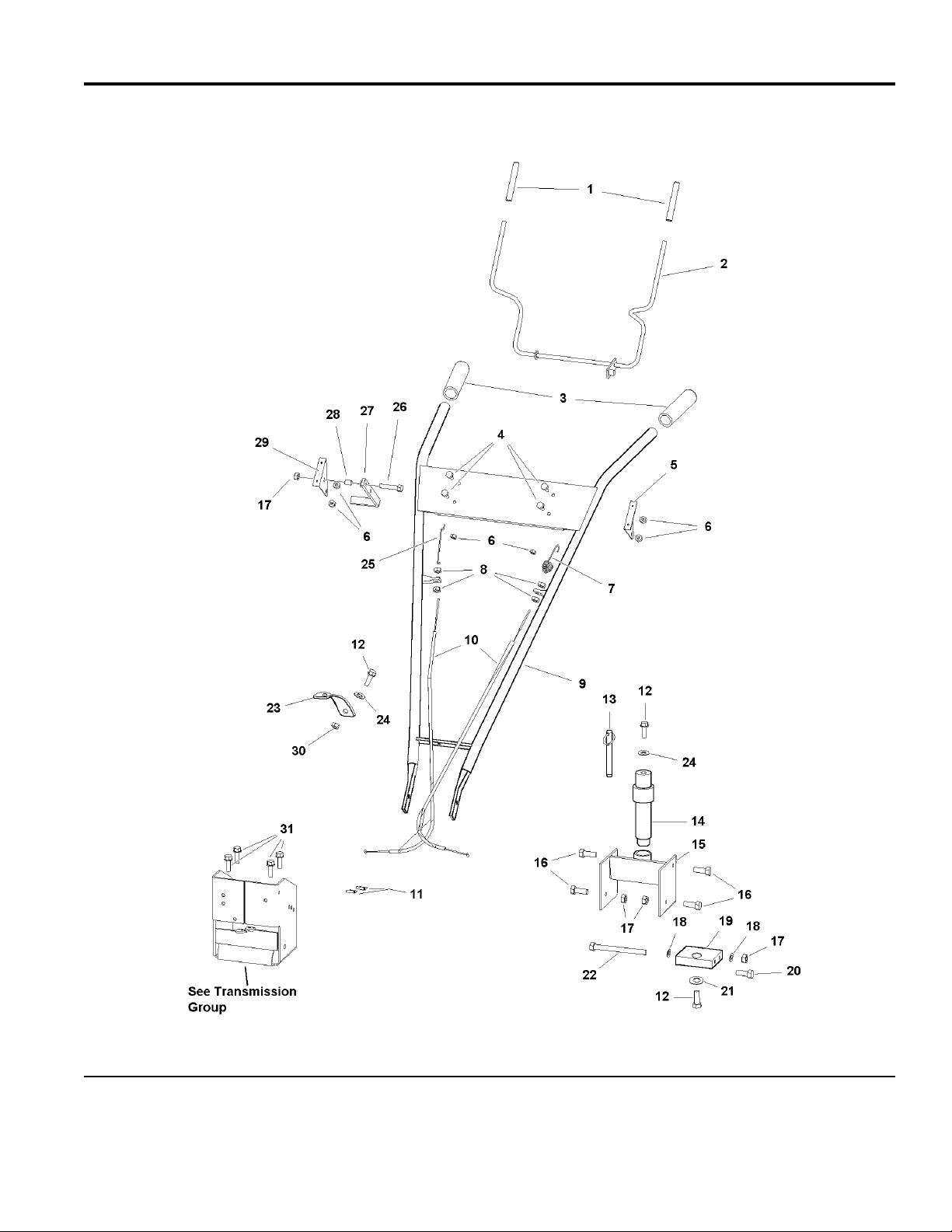
Handle Bar Group
PART NO. DESCRIPTIONREF NO QTY.
HANDLE GRIP, Drive Control Lever 1 1716699SM 2
LEVER, Drive Control 2 1722325SM 1
HANDLE GRIP 3 1719038SM 2
SCREW, Pan Head Phillips #10-24 x 1/2 4 1960392SM 4
BRACKET, Drive Control Lever LH 5 1716723SM 1
NUT, Hex Nylock, 10-24 6 1933896SM 6
SPRING, Forward Cable Adjustment 7 1716720SM 1
NUT, Hex Jam, 5/16-24 8 2820438SM 4
HANDLE BAR ASSEMBLY 9 1723692SM 1
CABLE ASSEMBLY 10 1719037SM 2
C-CLAMP 11 1719063SM 2
CAPSCREW, Hex Head, 5/16-18 x 3/4 12 1921332SM 3
PIN, Detent 13 1723703SM 1
PIVOT ROD ASSEMBLY 14 1723695SM 1
PIVOT MOUNT ASSEMBLY 15 1723696SM 1
CAPSCREW, Hex Head, 3/8-16 x 1 16 1921210SM 4
NUT, Hex, 3/8-16 17 1916950SM 5
WASHER 18 1924940SM 2
PIVOT, Handle Bar Mount 19 1723694SM 1
CAPSCREW, Hex Head, 3/8-16 x 1-1/4 20 1920415SM 1
WASHER 21 1716770SM 1
CAPSCREW, Hex Head 3/8-16 x 4 22 1922648SM 1
PIVOT, Hnadle Bar Height Adjustment 23 1723697SM 1
WASHER 24 1960044SM 2
LINK, Reverse 25 1716729SM 1
CAPSCREW, Hex Head, 5/16-18 x 1-1/4 26 1921977SM 1
HANDLE, Reverse 27 1716725SM 1
BUSHING, Pivot, 5/16 28 1716704SM 1
BRACKET, Drive Control Lever RH 29 1716722SM 1
NUT, Hex Flange Tow Way Lock, 5/16-18 30 1935048SM 2
BOLT, Hex Flange Head, 5/16-18 x 3/4 31 1921332SM 4
Footnotes
The above parts group applies to the following Mfg. Nos.:
1694162 - 7016 RT
1694909 - 7016 RT
© Copyright by Briggs & Stratton Corporation
Milwaukee, WI, USA. All rights reserved
2009
5
TP 400-2635-02-RT-S
Page 6
Not for
Reproduction
Hood, Drag Stake & Tine Group
NOTE: Unless noted otherwise,
use the standard hardware torque
specification chart.
986105
The above parts group applies to the following Mfg. Nos.:
1694162 - 7016 RT
1694909 - 7016 RT
© Copyright by Briggs & Stratton Corporation
Milwaukee, WI, USA. All rights reserved
2009
6
TP 400-2635-02-RT-S
Page 7

Not for
Reproduction
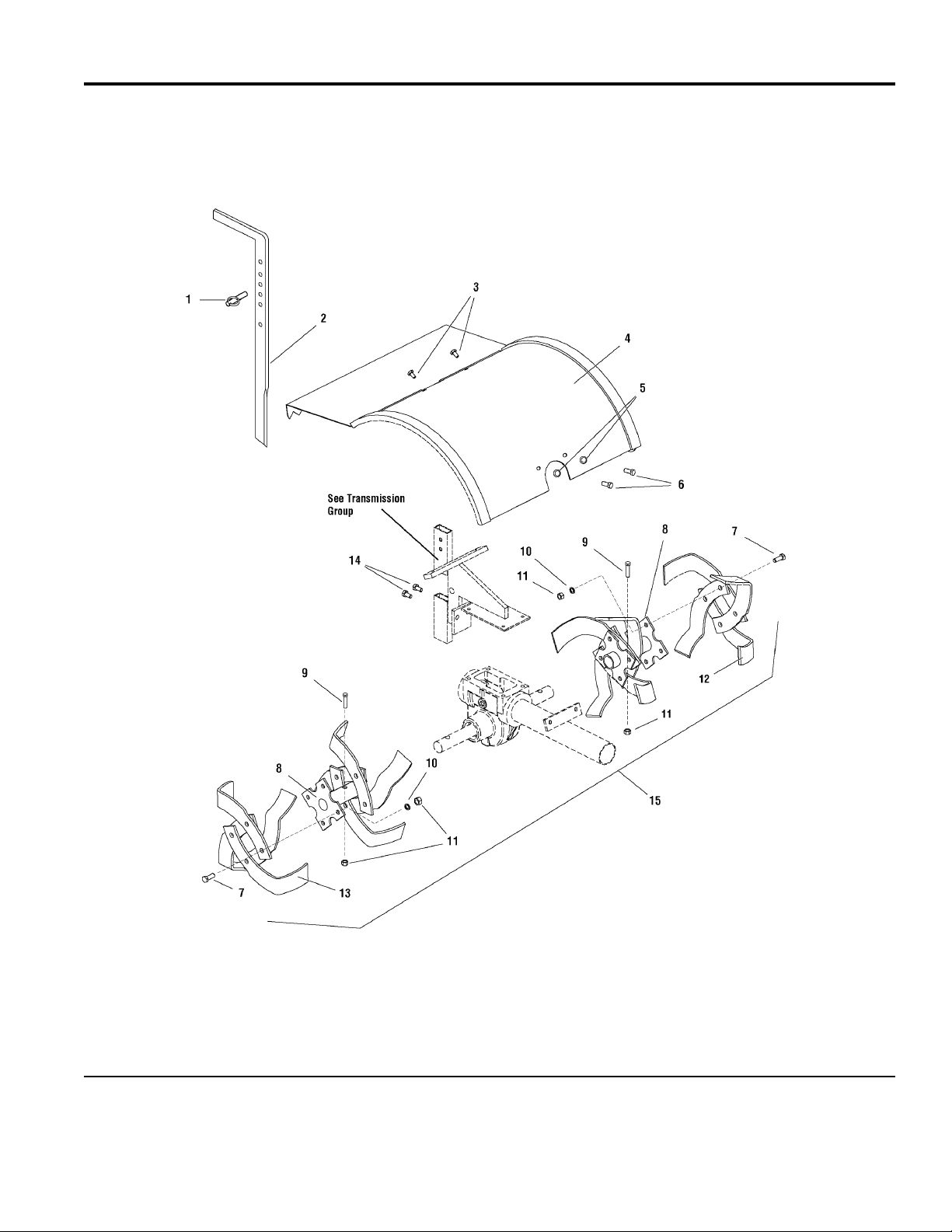
Hood, Drag Stake & Tine Group
PART NO. DESCRIPTIONREF NO QTY.
PIN, DETENT 5/16 1 1723703SM 1
LEVER, Depth Regulator 2 1723705SM 1
CAPSCREW, Hex Head, 1/4-20 x 1/2 3 1921958SM 2
HOOD, Tiller, No Decal 4 1722329SM 1
LOCKWASHER, 5/16 5 1917356SM 2
CAPSCREW, Hex Head, 5/16-18 x 1/2 6 1920787SM 2
CAPSCREW, Hex Head, 3/8-16 x 1 7 1921210SM 16
HOLDER, Tine Blade Left and Right 8 1716741SM 2
CAPSCREW, Hex Head, 3/8-16 x 1-3/4 9 1921971SM 2
LOCKWASHER, 3/8 10 1916965SM 18
NUT, Hex Centerlock, 3/8-16 11 1930645SM 18
TINE BLADE, Left Side 12 1716739SM 8
TINE BLADE, Right Side 13 1716737SM 8
BOLT, Hex Flange Head, 5/16-18 x 1/2 14 1716701SM 2
15 1716749SM 1
REPLACEMENT KIT, Tine Blade Holder & Tines (Includes Reference Nos. 7, 8, 9, 10, 11,
12, and 13)
Footnotes
The above parts group applies to the following Mfg. Nos.:
1694162 - 7016 RT
1694909 - 7016 RT
© Copyright by Briggs & Stratton Corporation
Milwaukee, WI, USA. All rights reserved
2009
7
TP 400-2635-02-RT-S
Page 8
Not for
Reproduction
Engine, Belts & Wheels Group
NOTE: Unless noted otherwise,
use the standard hardware torque
specification chart.
986106
The above parts group applies to the following Mfg. Nos.:
1694162 - 7016 RT
1694909 - 7016 RT
© Copyright by Briggs & Stratton Corporation
Milwaukee, WI, USA. All rights reserved
2009
8
TP 400-2635-02-RT-S
Page 9

Not for
Reproduction
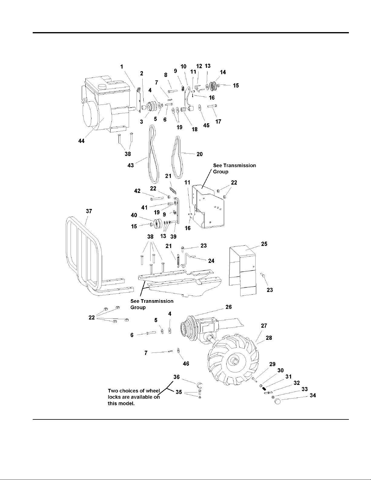
Engine, Belts & Wheels Group
PART NO. DESCRIPTIONREF NO QTY.
BRACKET, Engine 1 1722157SM 1
SPACER, Engine 2 1723711SM 1
PULLEY, Engine 2 Groove 3 1722158SM 1
WASHER 4 1716770SM 2
LOCKWASHER, Spring 5/16 5 1917356SM 2
CAPSCREW, Hex Head, 5/16-24 x 3/4 6 1921515SM 2
KEY, Parallel 7 2805850SM 2
CAPSCREW, Hex Head, 3/8-24 x 2 8 1960345SM 1
YOKE, Cable 9 1716728SM 2
ARM, Pivot 10 1722159SM 1
PIN, LINK Forward/Reverse 11 1716702SM 2
GUIDE, Belt Reverse 12 1722162SM 1
WASHER, 3/8 13 1924940SM 4
PULLEY, Idler Reverse 14 1716805SM 1
NUT, Hex Center Lock, 3/8-16 15 1930645SM 2
PIN, Cotter 16 1716703SM 2
BOLT, Flat Head, 5/16-24 x 1-1/2 17 1723710SM 1
PIVOT 18 1722160SM 1
WASHER, 5/16 19 1960044SM 3
V-BELT, Forward 20 1716766SM 1
SPRING, Idler Arm 21 1716802SM 2
NUT, Hex Flange 5/16-18 22 1935048SM 7
BOLT, Hex Flange Head, 5/16-18 x 3/4 23 1921332SM 3
GUIDE, Belt Forward 24 1722161SM 1
COVER, Belt 25 1722165SM 1
PULLEY, Transmission 2 Groove 26 1722163SM 1
WHEEL & TIRE ASSEMBLY, Tiller LH 27 1716773SM 1
WHEEL & TIRE ASSEMBLY, Tiller RH 28 1716775SM 1
CAPSCREW, Hex Socket Head, 1/4-20 x 2-3/32 29 1716782SM 2
WASHER, 1/4 30 1960151SM 2
SPRING 31 1716781SM 2
PIN, Lock 32 1716778SM 2
NUT, Hex KEPS 1/4-20 33 2828372SM 2
KNOB, Lock Out Set of Two 34 1716777SM 1
SETSCREW, Wheel Lockout 35 1722185SM 2
CLAMP, C Wheel Lockout 36 1722171SM 2
BUMPER, Guard 37 1721528SM 1
CAPSCREW, Hex Head, 5/16-18 x 1-3/4 38 1922127SM 8
ARM, Idler Forward 39 1722166SM 1
PULLEY, Forward Idler 40 1716803SM 1
Footnotes
Note* See your local Briggs & Straton distributor for Parts & Service.
The above parts group applies to the following Mfg. Nos.:
1694162 - 7016 RT
1694909 - 7016 RT
© Copyright by Briggs & Stratton Corporation
Milwaukee, WI, USA. All rights reserved
2009
9
TP 400-2635-02-RT-S
Page 10

Not for
Reproduction
Engine, Belts & Wheels Group
NOTE: Unless noted otherwise,
use the standard hardware torque
specification chart.
986106
The above parts group applies to the following Mfg. Nos.:
1694162 - 7016 RT
1694909 - 7016 RT
© Copyright by Briggs & Stratton Corporation
Milwaukee, WI, USA. All rights reserved
2009
10
TP 400-2635-02-RT-S
Page 11

Not for
Reproduction
Engine, Belts & Wheels Group
PART NO. DESCRIPTIONREF NO QTY.
SCREW, Hex Socket Shoulder, 5/16-18 x 3/8 41 1722168SM 1
CAPSCREW, Hex Head, 5/16-18 x 3-1/2 42 1925690SM 1
V-BELT, Reverse 43 1722144SM 1
ENGINE, 7HP B&S INTEK , 2005 - Engine Model 120412, Engine Type 0141-E1 44 * 1
ENGINE, 7HP B&S INTEK , 2006 - Engine Model 127312, Engine Type 0111-E1 44 * 1
WASHER, 3/8 45 1919384SM 1
WASHER 46 2860164SM 1
Footnotes
Note* See your local Briggs & Straton distributor for Parts & Service.
The above parts group applies to the following Mfg. Nos.:
1694162 - 7016 RT
1694909 - 7016 RT
© Copyright by Briggs & Stratton Corporation
Milwaukee, WI, USA. All rights reserved
2009
11
TP 400-2635-02-RT-S
Page 12

Not for
Reproduction
Transmission Group
NOTE: Unless noted otherwise,
use the standard hardware torque
specification chart.
986108
The above parts group applies to the following Mfg. Nos.:
1694162 - 7016 RT
1694909 - 7016 RT
© Copyright by Briggs & Stratton Corporation
Milwaukee, WI, USA. All rights reserved
2009
12
TP 400-2635-02-RT-S
Page 13

Not for
Reproduction
Transmission Group
PART NO. DESCRIPTIONREF NO QTY.
DIPSTICK (Threaded) 1 1718882SM 1
DIPSTICK (Push-In) 1 1723700SM 1
BOLT, Hex Flange Head, 5/16-18 x 3/4 2 1921332SM 12
COVER PLATE & MOUNT 3 1722327SM 1
BRACKET, Engine Mount LH 4 1716753SM 1
BRACKET, Engine Mount RH 5 1716752SM 1
NUT, Hex Flange 5/16-18 6 1935048SM 4
GASKET, Housing & Transmission Cover 7 1716789SM 2
SEAL, Housing 8 1716791SM 4
GASKET, Bearing Cap Front, Rear 9 1716792SM 2
CAP, Rear Bearing 10 1716796SM 1
SEAL, Oil, Drive Shaft 11 1716797SM 1
BOLT, Hex Flange Head, 1/4-20 x 3/4 12 1716798SM 3
PLUG, Pipe Socket Head, Oil Check, 1/4-18 13 1716790SM 2
TRANSMISSION, Tiller Casting 14 1722330SM 1
CAP, Rear Bearing 15 1716793SM 1
BOLT, Hex Flange Head, 1/4-20 x 7/8 16 1716795SM 3
BRACKET, Depth Regulator 17 1721511SM 1
GASKET KIT, Oil Seal (Includes Referance Nos. 7, 8, 9, and 11) 18 1716799SM 1
TRANSMISSION ASSEMBLY, Complete 19 1723701SM 1
Footnotes
The above parts group applies to the following Mfg. Nos.:
1694162 - 7016 RT
1694909 - 7016 RT
© Copyright by Briggs & Stratton Corporation
Milwaukee, WI, USA. All rights reserved
2009
13
TP 400-2635-02-RT-S
Page 14

Not for
Reproduction
Wheel & Tiller Shaft Group
NOTE: Unless noted otherwise,
use the standard hardware torque
specification chart.
985826
The above parts group applies to the following Mfg. Nos.:
1694162 - 7016 RT
1694909 - 7016 RT
© Copyright by Briggs & Stratton Corporation
Milwaukee, WI, USA. All rights reserved
2009
14
TP 400-2635-02-RT-S
Page 15

Not for
Reproduction
Wheel & Tiller Shaft Group
PART NO. DESCRIPTIONREF NO QTY.
CAP, Rear Bearing 1 1716793SM 1
SHIM SET, Rear Bearing Cap 2 1716825SM 1
SHIM, 0.062 THK 1-3/4 OD 1806 (As Required) 2 1716826SM 1
SHIM, 0.030 THK 1-3/4 OD 1807 (As Required) 2 1716827SM 1
SHIM, 0.015 THK 1-3/4 OD 1808 (As Required) 2 1716828SM 1
SHIM, 0.010 THK 1-3/4 OD 1809 (As Required) 2 1716829SM 1
BEARING, Tapered (Cone & Race) 3 1716810SM 2
SPACER, 1" ID x 11/4" OD 4 1716824SM 4
BUSHING 5 1716816SM 4
SHIM SET, Axle Spacer 6 1716815SM 4
SHIM, 0.062 THK 1-3/8" x OD 1705 (As Required) 6 1716817SM 1
SHIM, 0.030 THK 1-3/8" x OD 1706 (As Required) 6 1716818SM 1
SHIM, 0.015 THK 1-3/8" x OD 1707 (As Required) 6 1716819SM 1
SHIM, 0.010 THK 1-3/8" x OD 1708 (As Required) 6 1716820SM 1
RING, Snap, Internal Retainer 7 1716830SM 4
SEAL, Housing 8 1716791SM 4
RING, Snap, External Retainer 9 1716821SM 2
DRIVE SHAFT, Main 10 1722333SM 1
KEY, Parrallel Plan 1/4" x 1/4" x 1" 11 1716813SM 2
GEAR, Worm, Wheel Shaft 12 1716814SM 1
SHAFT ASSEMBLY, Wheel w/Lock Pin 13 1716812SM 1
CAP, Rear Bearing 14 1716796SM 1
SEAL, Oil, Drive Shaft 15 1716797SM 1
WASHER, 5/8" 16 2860164SM 1
SHAFT ASSEMBLY, Wheel w/Lock Pin 17 1716811SM 1
GEAR, Worm Shaft 18 1716823SM 1
Footnotes
The above parts group applies to the following Mfg. Nos.:
1694162 - 7016 RT
1694909 - 7016 RT
© Copyright by Briggs & Stratton Corporation
Milwaukee, WI, USA. All rights reserved
2009
15
TP 400-2635-02-RT-S
Page 16

Not for
Reproduction
Decal Group
NOTE: Unless noted otherwise,
use the standard hardware torque
specification chart.
986109
The above parts group applies to the following Mfg. Nos.:
1694162 - 7016 RT
1694909 - 7016 RT
© Copyright by Briggs & Stratton Corporation
Milwaukee, WI, USA. All rights reserved
2009
16
TP 400-2635-02-RT-S
Page 17

Not for
Reproduction
Decal Group
PART NO. DESCRIPTIONREF NO QTY.
DECAL, SIMPLICITY, w/Logo 1 1722551SM 1
DECAL, Console Forward/Reverse Instructions 2 1716734SM 1
DECAL, Hood, Operator Instructions Label 3 1716747SM 1
DECAL, Danger, Tine Hood Label 4 1716840SM 1
DECAL, 7016 RT 5 1723522SM 2
DECAL, Warning, Belt Cover 6 1716800SM 1
DECAL, Brush Bar 7 1716839SM 1
Footnotes
The above parts group applies to the following Mfg. Nos.:
1694162 - 7016 RT
1694909 - 7016 RT
© Copyright by Briggs & Stratton Corporation
Milwaukee, WI, USA. All rights reserved
2009
17
TP 400-2635-02-RT-S
Page 18

Not for
Reproduction
Hiller/Furrower Attachment
NOTE: Unless noted otherwise,
use the standard hardware torque
specification chart.
986035
The above parts group applies to the following Mfg. Nos.:
1694162 - 7016 RT
1694909 - 7016 RT
© Copyright by Briggs & Stratton Corporation
Milwaukee, WI, USA. All rights reserved
2009
18
TP 400-2635-02-RT-S
Page 19

Not for
Reproduction
Hiller/Furrower Attachment
PART NO. DESCRIPTIONREF NO QTY.
BOLT, Carriage, 3/8-16 x 1-1/2 1 1931352SM 2
BOLT, Carriage, 5/16-18 x 3/4 2 1931333SM 4
HILLER WING, Left 3 1723726SM 1
HILLER WING, Right (Not Shown) 3 1723727SM 1
WASHER, Flat, 5/16 4 1960044SM 4
LOCKWASHER, External Tooth, 5/16 5 2820426SM 4
WING NUT, 5/16-18 6 1933126SM 4
BOLT, Socket Head, 3/8-16 x 1-1/4 7 1960268SM 1
BRACKET 8 1723725SM 1
NUT, Nylock, 3/8-16 9 1919439SM 2
NUT, Hex, 3/8-16 10 1916950SM 1
BLADE, Furrower 11 1723724SM 1
HILLER / FURROWER ATTACHMENT, Complete 12 1686802SM 1
Footnotes
The above parts group applies to the following Mfg. Nos.:
1694162 - 7016 RT
1694909 - 7016 RT
© Copyright by Briggs & Stratton Corporation
Milwaukee, WI, USA. All rights reserved
2009
19
TP 400-2635-02-RT-S
Page 20

Not for
Reproduction
Page 21

Not for
Reproduction
Page 22

Not for
Reproduction
Page 23

Not for
Reproduction
Hardware Identification & Torque Specifications
No
Marks
0
1/4 3/4
1/2
21
1/4 3/4
1/2
1/4 3/4
1/2
1/4 3/4
1/2
4
Torque Specification Chart
FOR STANDARD METRIC MACHINE HARDWARE (Tolerance ± 20%)
Property
Class
Size Of
Hardware
M3
M4
M5
M6 7.3 10.3 12.1
M7 12.1 16.9 19.9
M8 17.7
M10 35 50
M12 61 86.2 103 140
M14
M16 147 210 250 340
M18 202 287 346 470
M20 290 405 486 660
M22 390 559 656 890
M24 497
M27 733 1032 1239 1680
M30 995 1401 1681 2280
M33
M36 1740 2441
M39 2249 3163
The guides and ruler furnished below are designed to
help you select the appropriate hardware.
010
Nut, M8
Thread
Diameter (mm)
Inside
Diameter (in)
Nut, 1/2-16
Class 5.6
in/lbs
ft/lbs
5.88
13.44
26.4
44.64
5.2
7.7
15
26
42
64
89
126
169
217
320
435
590
759
988
20
5.6
Nm. Nm. Nm.
.56
1.28
2.50
4.3
7.1
10.5
21
36
58
88
121
171
230
295
435
590
800
1030
1340
30
8.8
Class 8.8
in/lbs
ft/lbs
13.44 1.80
30.72 43.44 52.56
60.96
Class 10.9
in/lbs
ft/lbs
19.2 22.92
1.28
2.90
5.97 7.15
5.75
9.9
16.5
24
48
83
101
136 162 220
132
200
275
390
530
708
375
995
1350
1349
1902 2278 3090
1830
2360
3050
50
60
Body Length
40
Screw, M8- 1.25 x 25
Thread
Diameter (mm)
Threads
per inch
Body
Diameter
Screw, 1/2- 16 x 2
10.9
4.10
8.10
14
23
25
34
67
117
185
285
390
550
745
960
1400
1900
2580
3310
4290
80
Diameter
Distance between
threads (mm)
Threads
per inch
3
12.9
Class 12.9
in/lbs
ft/lbs
29
59
840 1140
2935 3980
3798
Body
Nm.
2.15
4.95
9.7
16.5
27
40
81
5150
90 10070
Body
Length (mm)
Body
Length (in)
Torque Specification Chart
FOR STANDARD MACHINE HARDWARE (Tolerance ± 20%)
Hardware
Grade
Size Of
Hardware ft/lbs Nm. ft/lbs Nm. ft/lbs Nm.
8-32
8-36
10-24
10-32
1/4-20
1/4-28
5/16-18 11 15.0 17 23.1 25 34.0
5/16-24 12 16.3 19 25.8 29 34.0
3/8-16 20 27.2 30 40.8 45 61.2
3/8-24 23 31.3 35 47.6 50 68.0
7/16-14 30 40.8 50 68.0 70 95.2
7/16-20 35 47.6 55 74.8 80 108.8
1/2-13 50 68.0 75 102.0 110 149.6
1/2-20 55 74.8 90 122.4 120 163.2
9/16-12 65 88.4 110 149.6 150 204.0
9/16-18 75 102.0 120 163.2 170 231.2
5/8-11 90 122.4 150 204.0 220 299.2
5/8-18 100 136 180 244.8 240 326.4
3/4-10 160 217.6 260 353.6 386 525.0
3/4-16 180 244.8 300 408.0 420 571.2
7/8-9 140 190.4 400 544.0 600 816.0
7/8-14 155 210.8 440 598.4 660 897.6
1-8 220 299.2 580 788.8 900 1,244.0
1-12 240 326.4 640 870.4 1,000 1,360.0
1. These torque values are to be used for all hardware
excluding: locknuts, self-tapping screws, thread forming
screws, sheet metal screws and socket head setscrews.
2. Recommended seating torque values for locknuts:
a. for prevailing torque locknuts - use 65% of grade 5
b. for flange whizlock nuts and screws - use 135% of
3. Unless otherwise noted on assembly drawings, all torque
values must meet this specification.
Common Hardware Types
Hex Head Capscrew
SAE Grade 2 SAE Grade 5 SAE Grade 8
in/lbs in/lbs
19
20
27
31
66
76
2.1
2.3
3.1
3.5
30
31
43
49
7.6 8 10.9 12 16.3
8.6 10 13.6 14 19.0
in/lbs
3.4
3.5
4.9
5.5
NOTES
torques.
grade 5 torques.
41
43
60
68
Washer
4.6
4.9
6.8
7.7
Standard Hardware Sizing
When a washer or nut is identified as 1/2” (M8), this is
Nominal size
the
(8mm metric thread diameter); if a second number is present
it represents the
When bolt or capscrew is identified as 1/2 - 16 x 2” (M8 - 1.25 x 50 ),
this means the
metric thread diameter), the second number,16, represents the
threads per inch, (1.25 thread diameter).
body length of the bolt or screw, 2 inches (50mm).
, meaning the
threads per inch
Nominal size
inside diameter
is 1/2 inch
(distance between threads).
, or body diameter is 1/2 inch (8mm
The final number is the
Lockwasher
Carriage Bolt
Hex Nut
Wrench & Fastener Size Guide
1/4” Bolt or Nut
Wrench—7/16”
M6 Bolt or Nut
Wrench—10mm
5/16” Bolt or Nut
Wrench—1/2”
M8 Bolt or Nut
Wrench—13mm
3/8” Bolt or Nut
Wrench—9/16”
M10 Bolt or Nut
Wrench—17mm
7/16” Bolt or Nut
Wrench (Bolt)—5/8”
Wrench (Nut)—11/16”
M12 Bolt or Nut
Wrench—19mm
1/2” Bolt or Nut
Wrench—3/4”
M14 Bolt or Nut
Wrench—22 mm
Page 24

Not for
Reproduction
IT IS THE POLICY OF BRIGGS & STRATTON CORP. TO IMPROVE ITS PRODUCTS
WHENEVER IT IS POSSIBLE AND PRACTICAL TO DO SO. WE RESERVE THE RIGHT TO
MAKE CHANGES OR ADD IMPROVEMENTS AT ANY TIME WITHOUT INCURRING ANY
OBLIGATION TO MAKE SUCH CHANGES ON PRODUCTS.
Briggs & Stratton Yard Power Products Group
3515 N. 124 Street / PO Box 702
Wauwatosa, WI 53222 USA
www.simplicitymfg.com
© Copyright by Briggs & Stratton Corporation
Milwaukee, WI, USA. All rights reserved
2009
 Loading...