

Page 1
Premium Rider (CE)
OPERATOR’S MANUAL
Manual Part No. 885193
CAUTION: Read and
follow all instructions.
15,5 HP Hydro Tractors 17,5 HP Hydro Tractors
Mfg. No. Brand Mfg. No. Brand
1
7800352 Snapper LT75 7800356 Snapper LT75
7800353 Snapper LT75 7800357 Snapper LT75
7800354 Simplicity Coronet 7800358 Simplicity Coronet
7800355 Simplicity Coronet 7800359 Simplicity Coronet
Revision A
Rev. Date 01/2009
Page 2

2
Page 3

Owner’s Information. . . . . . . . . . . . . . . . . . . . . . . . . . . . . . . . . . . . . . . . . . . 4
Safe Operation Practices . . . . . . . . . . . . . . . . . . . . . . . . . . . . . . . . . . . . . . 5
Safety and Operation Decals . . . . . . . . . . . . . . . . . . . . . . . . . . . . . . . . . . . 7
Assembly . . . . . . . . . . . . . . . . . . . . . . . . . . . . . . . . . . . . . . . . . . . . . .
. . . . . 9
Operation . . . . . . . . . . . . . . . . . . . . . . . . . . . . . . . . . . . . . . . . . . . . . . . . . . 13
Maintenance Chart . . . . . . . . . . . . . . . . . . . . . . . . . . . . . . .
. . . . . . . . . . . 22
Maintenance . . . . . . . . . . . . . . . . . . . . . . . . . . . . . . . . . . . . . . . . . . . . . . . 23
Troubleshooting Chart. . . . . . . . . . . . . . . . . . . . . . . . . . . . . . . . . . . . . . . . 34
Limited Warranty . . . . . . . . . . . . . . . . . . . . . . . . . . .
. . . . . . . . . . . . . . . . . 37
Product Specifications. . . . . . . . . . . . . . . . . . . . . . . . . . . . . . . . . . . SPEC-1
Table of Contents
en
3
Page 4

Owner’s Information
WARNING
Look for this symbol to indicate important safety
precautions. This symbol indicates: “Attention! Be
Al
ert! Your Safety Is At Risk.”
Know Your Product
Responsibility of the Owner
WARNING
This cutting machine is capable of amputating
hands and feet and throwing objects. Failure to
observe the following safety instructions could
result in serious injury or death to the operator or
bystanders.
It is the responsibility of the owner to follow the instructions contained in this manual.
en
If you understand the unit and how the unit operates,
you will get the best performance. As you read this
manual, compare the illustrations to the unit. Learn the
location and the function of the controls. To help prevent an accident, follow the operating instructions and
the safety rules. Keep this manual for future reference.
4
Page 5

Safe Operation Practices
Training
For Ride-On (Riding) Rotary Mower
Machines
Preparation
WARNING-Fuel is highly flammable.
Operation
en
1. Read the instructions carefully. Be familiar with the
controls and the proper use of the equipment.
2. Never allow children or people unfamiliar with
these instructions to use the mower. Local
regulations may restrict the age of the operator.
3. Never mow while people, especially children, or
pets are nearby.
4. Keep in mind that the operator or user is responsible for accidents or hazards occurring to other
people or their property.
5. Do not carry passengers.
6. All drivers should seek and obtain professional
and practical instruction. Such instruction should
emphasize:
a. the need for care and concentration when
working with ride-on machines;
b. control of a ride-on machine sliding on a slope
will not be regained by the application of the
brake. The main reasons for loss of control
are:
• insufficient wheel grip;
• being driven too fast;
• inadequate braking;
• the type of machine is unsuitable for its
task;
• lack of awareness of the effect of ground
conditions, especially slopes;
• incorrect hitching and load distribution.
1. While mowing, always wear substantial footwear
and long trousers. Do not operate the equipment
when barefoot or wearing open sandals.
2. Thoroughly inspect the area where the equipment
will be used and remove all objects which may
be thrown by the machine.
3. W
a. Store fuel in containers specifically
designed for this purpose.
b. Refuel outdoors only and do not smoke while
refuelling.
c. Add fuel before starting the engine. Never
remove the cap of the fuel tank or add fuel
while the engine is running or when the engine
is hot.
d. If fuel is spilled, do not attempt to start the
engine but move the machine away from the
area of spillage and avoid creating any source
of ignition until the fuel vapors have dissipated.
e. Replace all fuel tanks and container caps
securely.
4. Replace faulty silencers.
5. Before using, always visually inspect to see that
the blades, blade bolts, and cutter assembly are
not worn or damaged. Replace worn or damaged
blades and bolts in sets to preserve balance.
6. On multi-blade machines, take care as rotating
one blade can cause other blades to rotate.
1. Do not operate the engine in a confined space
where dangerous carbon monoxide fumes can
collect.
2. Mow only in daylight or in good artificial light.
3. Before attempting to start the engine, disengage
all blade attachment clutches and shift into
neutral.
4. Do not use on slopes of more than 10 degrees.
5. Remember there is no such thing as a “safe”
slope. Travel on grass slopes requires particular
care. To guard against overturning:
a. do not stop or start suddenly when going up or
downhill;
b. engage clutch slowly, always keep machine in
gear, especially when travelling downhill;
c. machine speeds should be kept low on slopes
and during tight turns;
d. stay alert for humps and hollows and other
hidden hazards;
e. never mow across the face of the slope, un-
less the mower is designed for this purpose.
6. Use care when pulling loads or using heavy
equipment.
a. Use only approved drawbar hitch points.
b. Limit loads to those you can safely control.
c. Do not turn sharply. Use care when driving in
reverse.
d. Use counterweight(s) or wheel weights when
suggested in the Operator’s Manual.
7. Watch out for traffic when crossing or near
roadways.
8. Stop the blades rotating before crossing surfaces
other than grass.
5
Page 6

Safe Operation Practices
Maintenance and Storage
en
9. When using any attachments, never direct the
discharge of material toward bystanders nor allow
anyone near the machine while in operation.
10. Never operate the mower with defective guards or
shields, or without safety protective devices in
place.
11. Do not change the engine governor settings or
overspeed the engine. Operating an engine at
excessive speed may increase the hazard of
personal injury.
12. Before leaving the operator’s position
a. disengage the power take-off and lower the
attachments;
b. change into neutral and set the parking brake;
c. stop the engine and remove the key.
13. Disengage drive to attachments, stop the engine,
and disconnect the spark plug wire(s) or remove
the ignition key
a. before cleaning blockages or unclogging
chute;
b. before checking, cleaning, or working on the
mower;
c. after striking a foreign object. Inspect the
mower for damage and make repairs before
restarting and operating the equipment;
d. if the machine starts to vibrate abnormally
(check immediately).
14. Disengage drive to attachments when transporting
or not in use.
15. Stop the engine and disengage drive to the
attachment
a. before refuelling;
b. before removing the grass bagger;
c. before making height adjustment unless
adjustment can be made from the operator’s
position.
16. Reduce the throttle setting during engine run-out
and, if the engine is provided with a shut-off valve,
turn the fuel off at the conclusion of mowing.
17. Before and when backing, look behind and down
for small children.
18. Use extra care when approaching blind corners,
shrubs, trees or other objects that may obscure
vision.
1. On multi-blade machines, take care as rotating
one blade can cause other blades to rotate.
2. When machine will be parked, stored or left
unattended, lower the cutting means unless a
positive mechanical lock is used.
3. Keep all nuts, bolts, and screws tight to be sure the
equipment is in safe working condition.
4. Never store the equipment with fuel in the tank
inside a building where fumes may reach an open
flame or spark.
5. Allow the engine to cool before storing in any
enclosure.
6. To reduce the fire hazard, keep the engine,
silencer, battery compartment and fuel storage
area free of grass, leaves, or excessive grease.
7. Check the grass bagger frequently for wear or
deterioration.
8. Replace worn or damaged parts for safety.
9. If the fuel tank has to be drained, this should be
done outdoors.
6
Page 7
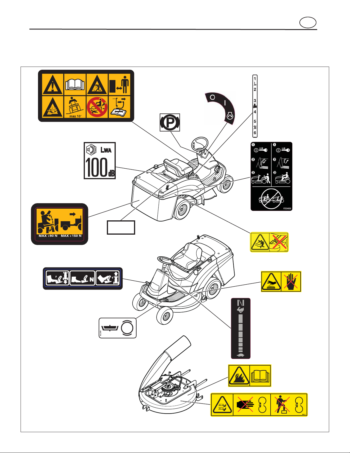
Safety and Operation Decals
Decal - Operating Instructions (CE)
(48x4032)
Decal - Parking
Brake (48x726)
Decal - Ignition
Switch (1722
806)
Decal - Cutting
Height (885253)
Decal - Roll Release
(1723425)
Decal - Hot Surface
(885216)
Decal - Thr
ottle
Control (885171)
Decal - Discharge Tube
(1721107)
Decal - Fire
Hazard (885218)
Decal - Brake/Clutch
Co
ntrol (48x736)
Decal - Speed Control
Pedal (885169)
Decal - Draw Bar Load
(48x511)
Decal - Noise Level
(48x
5911)
ID Tag
Decal - Sever Hazard (885217)
en
All safety and operation decals should be carefully
read and followed. Serious personal injury and/or
equipment damage can result when these decals are
not followed.
48x4032
NOTE: If any of these safety or operation decals are
lost or damaged, replace them at once. See your
local dealer for replacements.
_
(
)
LB
20
_
(
)
LB
34
7
Page 8
Safety and Operation Decals
1
2
3
5
9
11
12
13
4
7
8
10
14
15
6
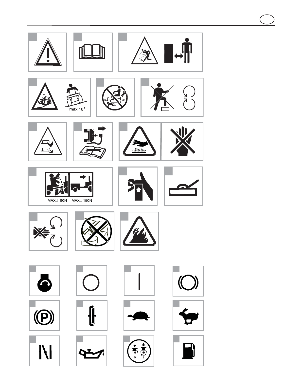
IMPORTANT: The following symbols are located on your unit or on
literature supplied with the product.
Before you operate the unit, learn
and understand the purpose for
each symbol.
Safety Warning Symbols
1
2
3
4
5
6
7
8
9
10
11
12
13
14
15
Control and Operating
Symbols
1
2
3
4
5
6
7
8
9
10
11
12
en
WARNING.
IMPORTANT: Read Owner’s
Manual Before Operating This
Machine.
WARNING: Thrown Objects.
Keep Bystanders Away. Read
User Instructions Before Operating This Machine.
WARNING: Do Not Use This
Machine On Slopes Greater
Than 10 Degrees.
DANGER: Keep People, Especially Children, Away From
Unit.
DANGER: Stay Clear Of Mower
Blade As Long As Engine Is
Running.
DANGER: Keep Feet And
Hands Away From Rotating
Blade.
1
2
3
4
DANGER: Disconnect Spark
Plug Wire Before Servicing
Unit.
WARNING: Hot Surface.
WARNING: Use Caution When
Connecting Or Disconnecting
Accessories.
WARNING: Crushed Fingers.
IMPORTANT: Follow Instructions In Owner’s Manual To
Level The Deck.
DANGER: Stay Clear Of Mower
Blade As Long As Engine Is
Running.
WARNING: Discharge Tube. Do
not operate as a bagger unless
discharge chute is in place.
WARNING: Fire Hazard. Yard
debris is combustible. Keep
unit cleaned of debris.
Engine Start
Engine Stop
5
6
9
10
11
7
8
12
Engine Run
Brake
Parking Brake
Clutch
Slow
Fast
Choke
Oil
Blade Rotation Control
Fuel
8
Page 9
Assembly
NOTES: All fasteners are in the parts bag. Do not discard any parts or material until the unit is as
sembled.
Before doing any assembly or maintenance to the
mower, remove the wire from the spark plug.
Install the Seat
Figure 2
NOTE: Install the washers on the left side only.
1
3
7
5
4
6
2
5
Figure 2
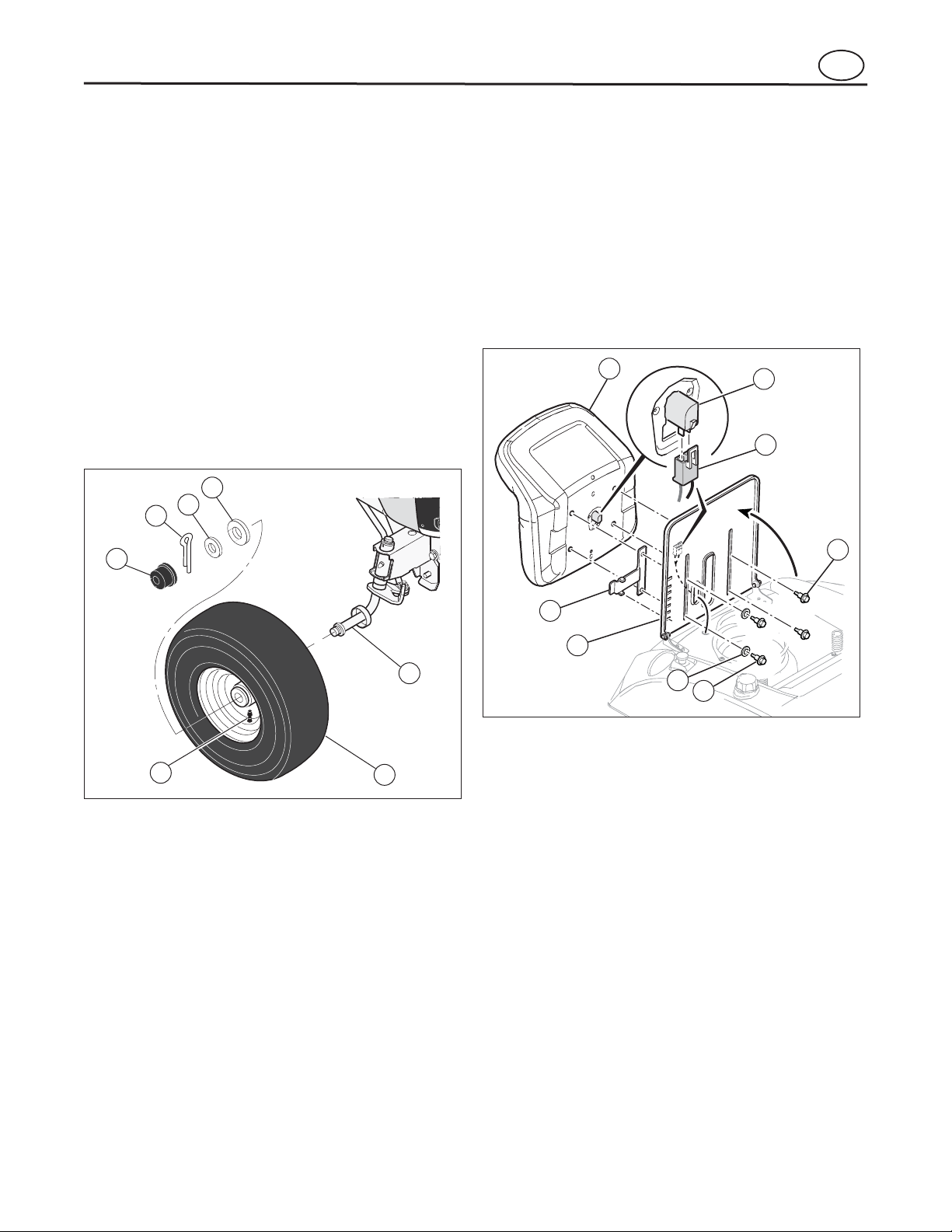
Install the Front Wheels
Figure 1
Figure 1
1
2
3
7
4
6
5
en
1. Make sure the valve stem (1) is to the outside (see
2. Slide the front wheel (2) onto the spindle (3).
3. Faster the front wheel (2) with washers (4 and 5),
and cotter pin (6) Bend the ends of the cotter pin
apart to keep the front wheel on the spindle.
4. If your model has hub caps (7), install the hub
caps. Make sure the washers hold the hub caps in
place.
5. Repeat for opposite side.
).
1. Carefully remove the plastic bag from the seat.
2. Raise the seat support (1) (see F
3. Align the holes in the seat (2) to the slots in the
seat support.
4. Install the seat (2) to the seat support (1) and
adjustment lever (3) with washers (4) and bolts (5).
5. Connect the wiring harness (6) to the seat switch
(7) under the seat.
).
6. Lower the seat to the normal operating position.
7. Check the operation of the seat adjustment.
a. If the seat needs adjustment, raise the adjust-
ment lever (3) toward the seat and move the
seat to the desired position.
b. Release the adjustment lever to lock the seat
in place.
9
Page 10
Assembly
Figure 4
Figure 3
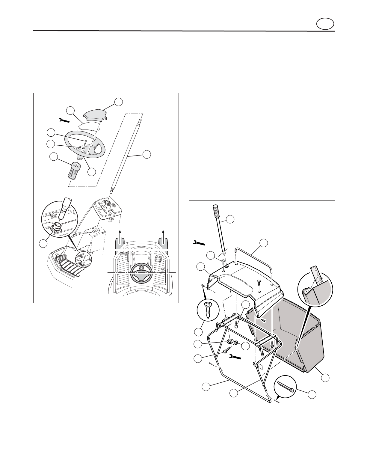
Assemble the Grass Bag
Figure 4
Assemble the Steering Wheel
Figure 3
Figure 3
en
1. Make sure the front wheels point forward as shown
3/8
.
7
3
) over the console.
8
2
in F
2. Slide the bellows (1, F
3. Slide the steering post (2) into the console.
4
5
1
1. Slide the bottom tube (1) onto the bagger frame (2)
(see F
2. Align the holes in bottom tube the with hole in the
bagger frame.
3. Install the cotter pins (3) into holes and bend the
ends to secure to the frame.
4. Slide the frame assembly onto the grass bag (4).
5. Attach the bag clips to the frame assembly.
6. Align the bagger cover (5) to holes in frame.
7. Use screws (6) and (7) to assemble the side and
top of the cover to the bagger frame.
8. Assemble the bagger handle (8) thru hole in cover
and frame.
9. Secure the bagger handle with washer (9), screw
(10), and nut (11).
10. Install rear bagger handle (12) to cover using two
screws (13).
).
6
4. Attach the steering wheel (3) to the steering post
(2) with screw (4) and washer (5). Tighten screw
but be careful not to over-tighten.
a. Push on the steering wheel. The steering post
will lock onto the pinion gear (6).
b. Pull on the steering wheel. Make sure that the
steering post is locked in place.
5. Install the plate (7) and cover (8) to the steering
wheel.
5/16
5
6
9
10
8
12
7
13
11
7/16
4
1
2
3
10
Page 11
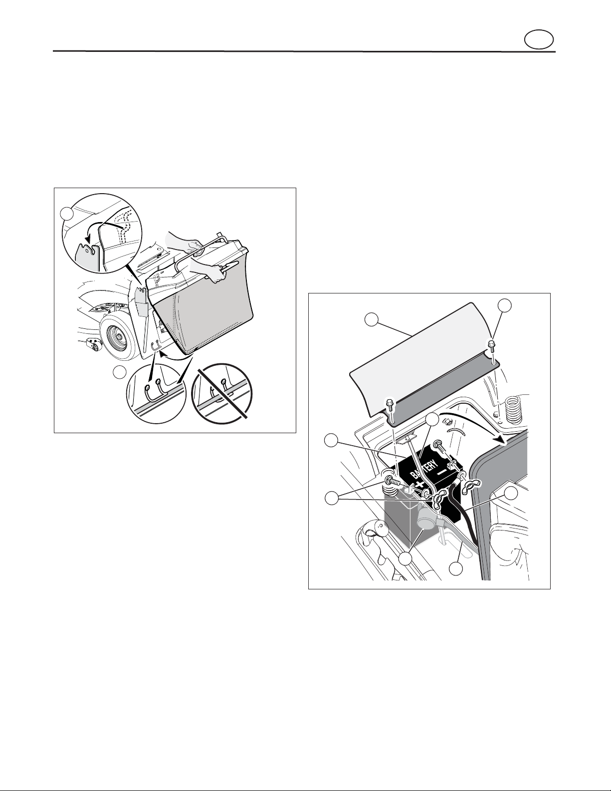
Mount the Grass Bag
Figure 5
Maintenance Free Battery
IMPORTANT: Before you attach the battery cables to
the battery, check the battery date. The battery da
te
tells if the battery must be charged.
see Figure 2
Figure 6
Assembly
Figure 6
Figure 5
en
1. Mount the grass bag assembly onto the rear bagger brackets as shown (see F
a. Use one hand to grab onto the handle at the
rear of the bag frame assembly.
b. Use the other hand to hold the top bagger han-
dle and guide the bag frame assembly onto
the rear bagger brackets.
1
).
1. Raise the seat support (s
2. Remove two screws (1) and battery cover (2) (see
3. Check the side of the battery (3) for the location of
the battery date.
a. If the battery is put into service before this
b. If the battery is put into service after this date,
).
date, the battery cables can be attached
without charging the battery. See “Install the
Battery Cables.”
the battery must be charged. See “Charge the
Battery.”
2
).
1
2
2. When mounting the bagger frame assembly, hold
the bottom of the grass bagger assembly slightly
away from the rear plate.
3. Rotate the grass bagger assembly until it locks in
place.
4
3
7
5
6
8
11
Page 12
Assembly
Figure 6
Charge the Battery
WARNING
When you charge the battery, do not smoke. Keep
the battery away from any sparks. The fumes from
the battery acid can cause an explosion.
Install the Battery Cables
WARNING
To prevent sparks, fasten the red cable to the
positive (+) terminal before you connect the
negative (-) black cable.
Figure 6
Prepare the Engine
NOTE: The engine was shipped from the factory filled
with oil. Check the level of the oil. Add oil as needed.
WARNING
Follow the engine manufacturer’s instructions for
the type of fuel and oil to use. Always use a safety
fuel container. Do not smoke when adding fuel to
the engine. When inside an enclosure, do not fill
with fuel. Before you add fuel, stop the engine. Let
the engine cool for several minutes.
Check the Tires
Check the Level of the Mower Deck
Assemble the Fuel Cap
en
1. To disconnect the battery retainer (4), push in on
the lower end of the battery retainer (see F
2. Remove the battery (3) from the opening between
the engine and the seat support.
3. Remove the protective cap from the battery
terminals.
4. Use a 12 volt battery charger to charge the battery.
Charge at a rate of 6 amps for one hour. If you do
not have a battery charger, have an authorized
service center charge the battery.
5. Install the battery. Make sure the positive (+) terminal is on the right side.
6. Connect the battery retainer.
Check the air pressure in the tires. Tires with too much
air pressure will cause the unit to ride rough. Also, the
wrong air pressure will keep the mower deck from cutting level. The correct air pressure is: Front Tires 0,97
BAR (14 PSI), Rear Tires 0,69 BAR (10 PSI). The tires
were over inflated for shipment.
).
Make sure the level of cut is still correct. After you mow
a short distance, look at the area that was cut. If the
mower housing does not cut level, see the instructions
to “Level the Mower Deck” in the Maintenance section
of this manual.
See the engine manufacturer’s instructions for the type
of fuel and oil to use. Before you use the unit, read the
information on safety, operation, maintenance, and
storage.
1. Remove the protective caps from the battery
terminals (see F
2. Slide the terminal boot (5) onto the red cable (6).
3. Connect the red cable to the positive (+) terminal
with the fasteners (7).
4. Connect the black cable (8) to the negative (-)
terminal with the fasteners (7).
5. Install the battery cover (2) with the two
screws (1).
).
The fuel cap will be shipped in the Parts Bag and tape
will be placed over the fuel tank opening during shipment. Before operation, remove tape from opening on
fuel tank and install fuel cap.
12
Page 13
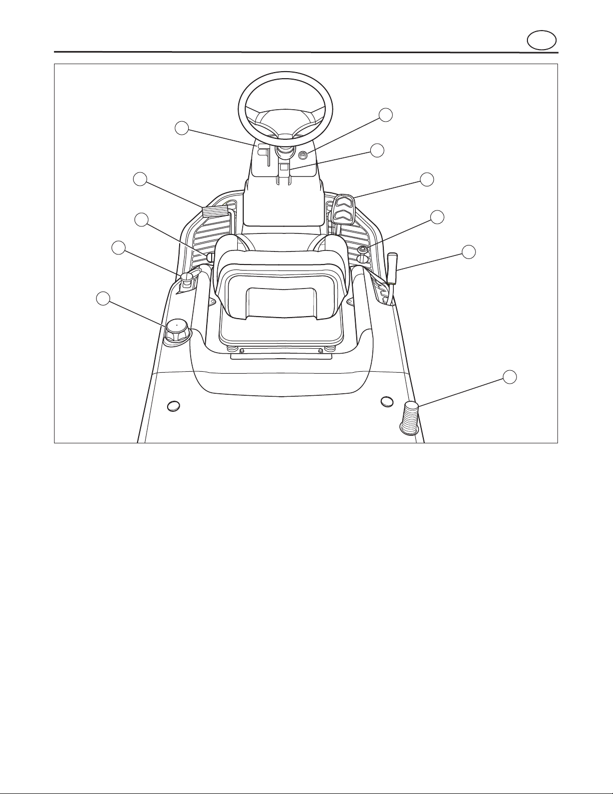
Operation
Location of Controls
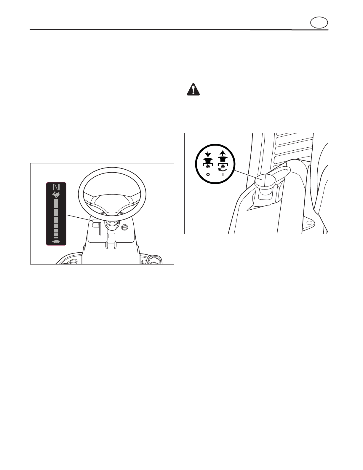
Throttle Control Lever (1):
Figure 7
Clutch/Brake Pedal (2):
Ignition Switch (3):
Parking Brake Knob (4):
Forward Speed Control Pedal (5):
1
2
3
4
5
6
7
8
10
9
11
Figure 7
Reverse Speed Control Pedal (6):
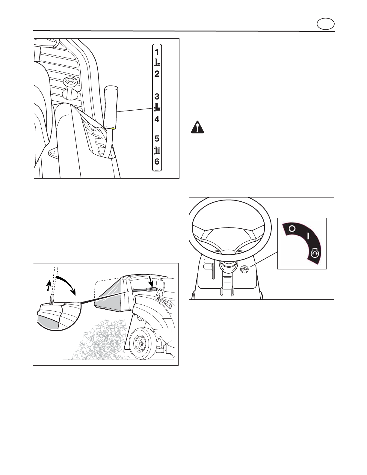
Lift Lever (7):
Blade Rotation Control (8):
Fuel Tank (9):
Grass Bagger Handle (10):
Seat Adjustment Lever (11):
en
to increase or decrease engine speed (see F
Move the throttle up to increase engine speed and
down to decrease engine speed. Always operate at
FULL throttle.
The first function is a clutch. The second function is a
brake.
stop the engine. Never leave the ignition switch in the
RUN position with the engine stopped. This drains the
battery.
used to lock the parking brake when the tractor is
stopped. Fully depress the brake pedal and pull up on
the knob to engage the parking brake.
ground speed is controlled by the forward speed control pedal. Depress the pedal to increase forward
ground speed.
Use the ignition switch to start and
Use the throttle control lever
The pedal has two functions.
The parking brake knob is
The tractor’s forward
).
ground speed pedal to control the reverse ground
speed of the tractor.
height. There are six cutting height levels available
(1 - Lowest Cut, 6 - Highest Cut).
trol to start and stop the rotation of the blade. Pull up on
the switch to engage the blade rotation control and
push down to disengage.
to leave room for heat expansion.
opens the bagger so that it can be emptied and closed
for mowing.
just the location of the seat. Release lever to lock seat
in place.
The lift lever controls the mower cutting
Use the blade rotation con-
To add fuel, remove the filler cap. Be sure
Use the reverse
The grass bagger handle
Pull up on the lever to ad-
13
Page 14
Operation
Use the Throttle Control
Figure 8
Important! Before You Start Mowing
Use the Blade Rotation Control
Figure 9
WARNING
Always keep your hands and feet away from the
blade, deflector opening, and the mower deck when
the eng
ine runs.
Figure 8
Figure 9
NOTE: This model is equipped with a bag full indicator. With the blade rotation control engaged, a
buzzer will sound when the bag is full.
en
• Check the engine oil.
• Fill the fuel tank with fuel.
• Check the air pressure of the tires.
• Check the level of the mower housing.
• Attach the battery cables.
Use the throttle control to increase or decrease the
speed of the engine.
1. Move the throttle/choke control completely
forward to the CHOKE position to start a cold
engine (see F
).
Use the blade rotation control to engage the blade(s).
1. Before you start the engine, make sure the blade
rotation control is in the DISENGAGE position (see
).
2. The FAST position is marked with a detent. For
normal operation and when using a grass bagger,
move the throttle control to the FAST position. For
maximum charging of the battery and for a cooler
running engine, operate the engine in the FAST
position.
3. The engine governor is set at the factory for maximum performance. Do not adjust the governor to
increase the speed of the engine.
2. To engage the blade, pull the blade rotation control
upward to the ENGAGE position.
3. To stop the blade, move the blade rotation control
to the DISENGAGE position. Before you leave the
operator’s position, make sure the blade(s) has
stopped rotating.
4. Before you ride the unit across a sidewalk or a
road, move the blade rotation control to the
DISENGAGE position.
14
Page 15
Attachments
Operation
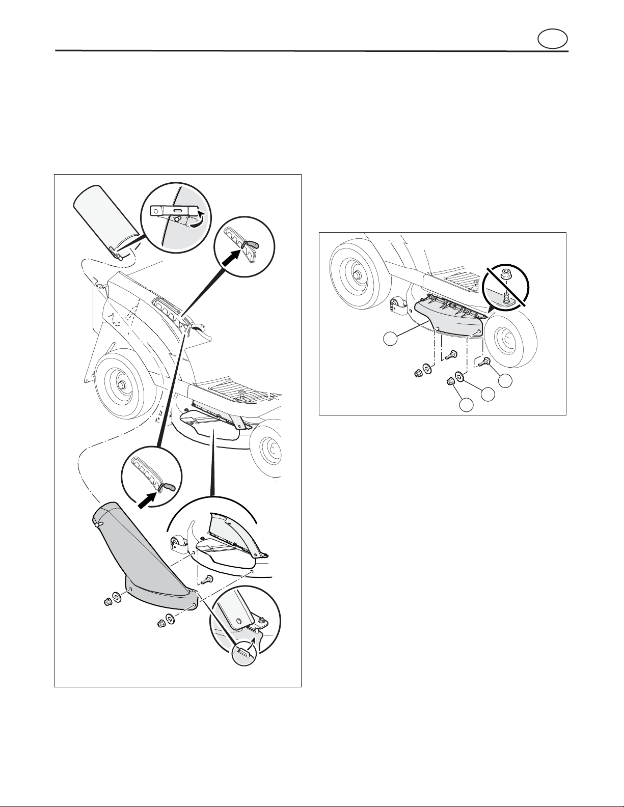
Install the Mulcher Cover
Figure 10
Figure 11
Figure 21
DO NOT
remove
4
1
2
3
Figure 11
2
3
1
4
For installation
5
Figure 10
en
This unit can use attachments like a dump cart and a
dethatcherizer. This unit cannot use attachments that
engage the ground like a plough, a disk harrow, or a
cultivator.
For the dump cart, the maximum weight is 90 kg (200
lbs).
The mulcher cover lets you mulch the grass for a clean,
fine cut. Install as follows.
1. Follow the steps shown in F
rear discharge chute and chute extension.
2. Mount the mulcher cover (1) to the mower deck
with the bolts (4), washers (2), and flange nuts (3)
(see F
3. For mulching operation, install mulch blade provided as an accessory part. Refer to "Remove and
Install the Blade" to assemble (see F
).
to remove the
).
15
Page 16
Operation
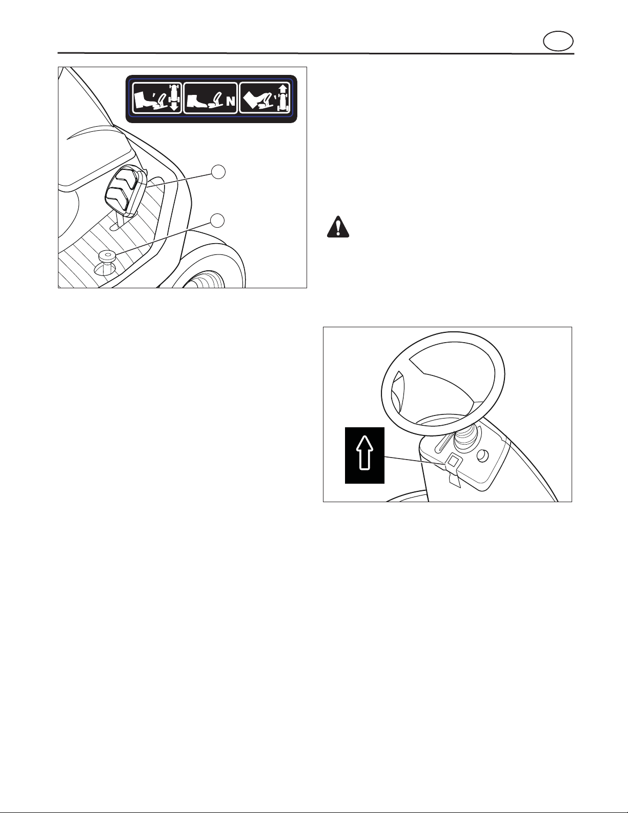
Use the Speed Control Pedals
NOTE: Do not use the left brake pedal in normal operation. Only use the left brake pedal to quickly stop in an
emergency.
Drive Forward
A, Figure 12
Figure 13
Figure 8
Figure 14
Drive In Reverse
Figure 14
A
B
Figure 12
Figure 13
The drive system uses a Hydrostatic Automatic Drive
Transmission. The hydrostatic transmission is very
easy to operate. This type of drive system does not require a shift lever or a clutch pedal.
The speed and direction of travel is controlled by a forward speed control pedal and reverse speed control
pedal operated with your right foot.
1. The automatic drive disconnect must be in the
DRIVE position (see A
2. Slowly release your left foot from the brake pedal
(see F
3. Move the throttle control to the FAST position (see
4. Slowly push the forward speed control pedal (1)
to enable forward ground speed (see F
5. To increase forward speed, slowly push down on
the forward speed control pedal. To reduce forward
speed, slowly release the forward speed control
pedal until the unit slows to the desired speed.
1. Before driving in reverse, look to the rear. Look
behind and down for small children to ensure
safety.
2. Remove your foot from the forward speed control
pedal (1) (see F
3. Slowly push the reverse speed control pedal (2) to
enable reverse ground speed.
4. To increase reverse speed, slowly push down on
the reverse speed control pedal. To reduce reverse
speed, release the reverse control pedal until the
unit slows to the desired speed.
).
).
).
).
).
en
16
Page 17
Operation
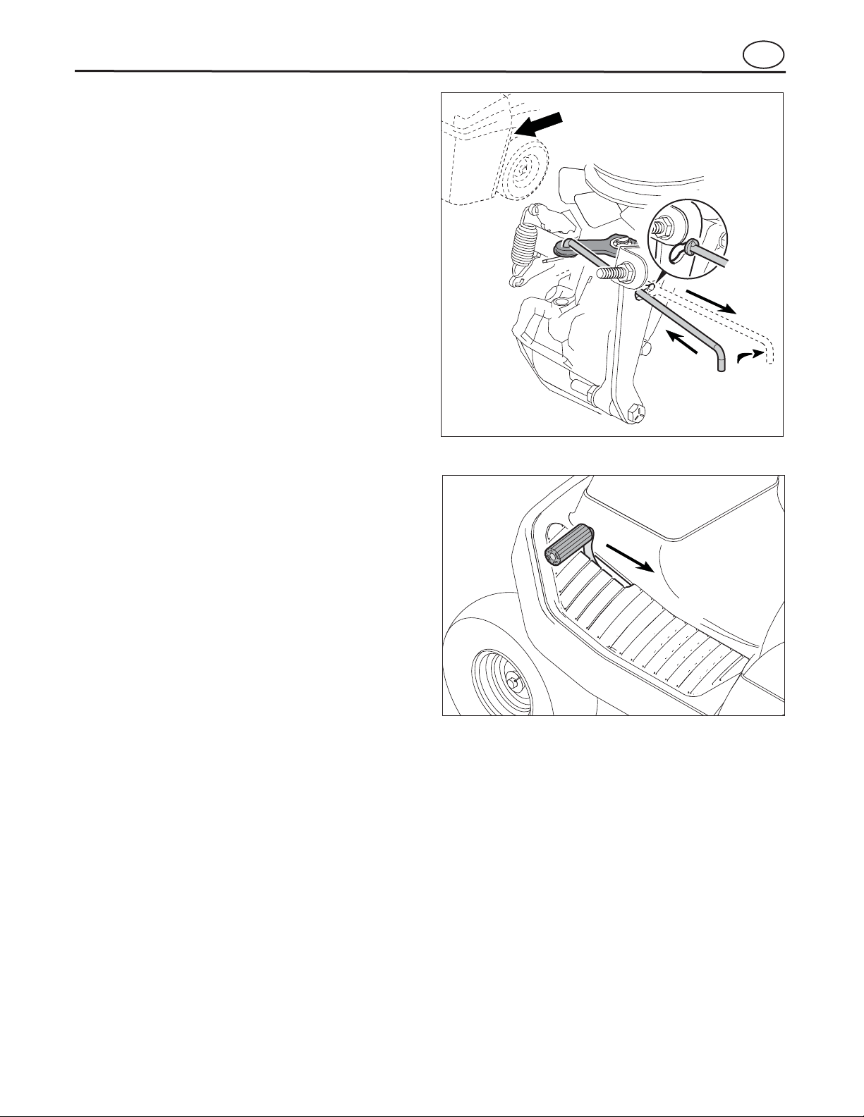
Disconnect the Transmission
B, Figure 12
NOTE: In cold weather, the heavy viscosity oil in the
transmission will make the unit difficult to pus
h.
WARNING
Before you leave the operator’s position, release the
speed control pedal. Set the parking brake. Move
the blade rotation control to the DISENGAGE
position. Stop the engine and remove the ignition
key.
Use the Parking Brake
Figure 13
Figure 15
Figure 15
Change the Cutting Height
Figure 16
Figure 9
Change Directions
CAUTION: To change directions, do not use the left
brake pedal. Use only the speed co
ntrol pedals.
Figure 14
Figure 14
2
1
1. Slowly remove your foot from the forward speed
control pedal (1) or reverse speed control pedal (2)
(see F
or reverse speed control pedal will automatically
return to the NEUTRAL position.
2. When the unit stops, slowly move the forward
speed control pedal or reverse speed control pedal
to the desired direction.
). The forward speed control pedal
en
1. Fully depress the clutch/brake pedal (see
2. Pull up the parking brake knob (F
3. Remove your foot from the clutch/brake pedal and
then release the parking brake knob. Make sure
the parking brake will hold the unit.
4. To release the parking brake, fully depress the
clutch/brake pedal. The parking brake will automatically release.
).
).
To push the unit, use the automatic drive disconnect to
release the transmission. The automatic drive disconnect is located near the right rear tire.
1. The engine must be off.
2. Move and latch the automatic drive disconnect in
the PUSH position (see B
mission is now released and the unit can be
pushed.
3. To engage the transmission, unlatch and push-in
the automatic drive disconnect. The transmission
is now connected and ready to operate.
). The trans-
To change the cutting height, raise or lower the lift lever
as follows.
1. Move the lift lever forward to lower the mower
deck and back to raise the mower deck (see
2. When you ride on a sidewalk or road, move the lift
lever to the highest position and move the blade
rotation control to the DISENGAGE position (see
).
).
17
Page 18
WARNING
Make sure the parking brake will hold the unit.
Figure 8
Figure 18
Stop the Unit
Figure 13
Figure 9
Figure 14
Figure 15
Operation
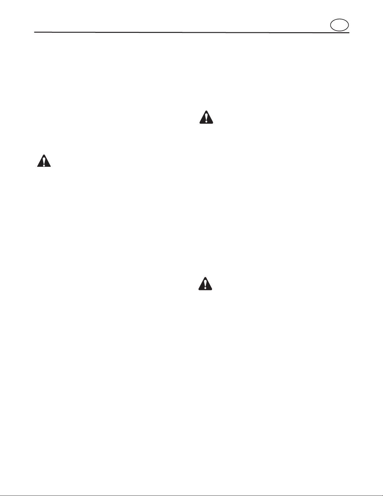
Empty the Grass Bagger
Figure 17
Figure 17
Figure 18
Figure 16
en
1. Completely push the clutch/brake pedal forward to
stop the unit (see F
pedal.
2. Push the blade rotation control down to the
DISENGAGE position (see F
3. Release the speed control pedal to the NEUTRAL
position (see F
4. Set the parking brake (see F
). Keep your foot on the
).
).
).
5. Move the throttle control to the SLOW position
(see F
6. Turn the ignition key to the OFF position to stop the
engine (see F
).
).
1. Extend the grass bagger handle and rotate forward
until the grass bagger assembly is completely
open at the bottom (see F
2. Empty the grass from the bagger.
3. Rotate the grass bagger assembly back to the
closed position for mowing.
).
18
Page 19
Operation
Operate the Mower Deck
WARNING
The mulcher cover is a safety device. Do not
remove the mulcher cover. The deflector forces the
discharged material toward the ground. Always
keep the deflector in the down position. If the
deflector is dam
aged, replace the deflector with
an original equipment part from an authorized
service center.
IMPORTANT: When you operate with the mower deck,
always operate with the throttle control in the FAST
po-
sition.
Figure 18
Figure 16
Figure 8
Figure 9
Figure 14
NOTE: When you mow in heavy grass or mow with a
bagger, operate the speed control pedals in the lowest
speed.
Before Starting the Engine
Check the Oil
NOTE: The engine was shipped from the factory filled
with oil. Check the level of the oil. Add oil as needed.
See the engine manufacturer’s instructions for the type
of fuel and oil to use.
NOTE: Do not check the level of the oil while the
engine runs.
Figure 8
WARNING
For better control of the unit, select a safe speed.
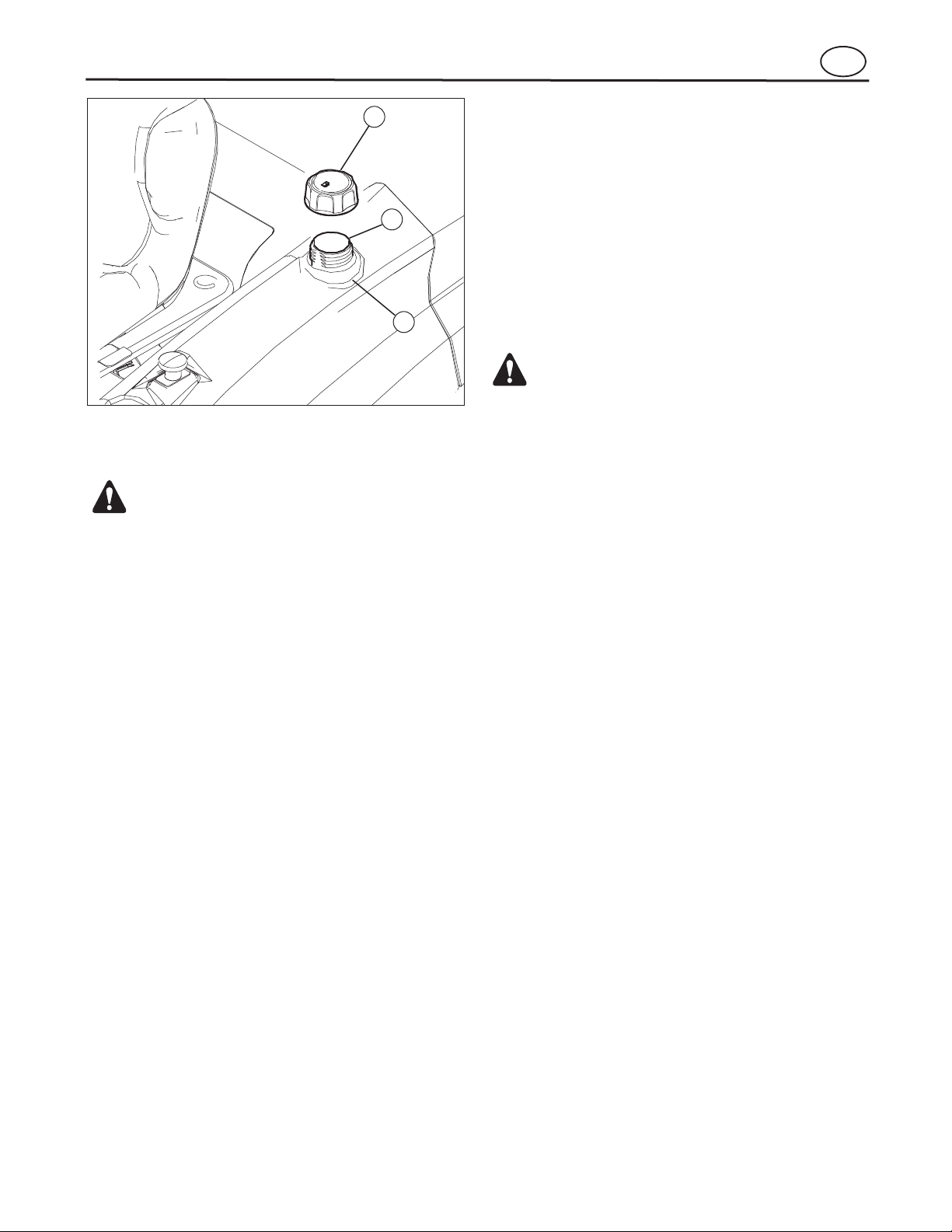
Add Fuel
WARNING
Always use a safety fuel container. Do not smoke
when adding fuel to the fuel tank. Do not add fuel
when you are inside an enclosure. Before you add
fuel, stop the engine and let the engine cool for
several minutes.
Figure 20
NOTE: Do not use premium unleaded fuel. Make sure
the fuel is fresh and clean. Leaded fuel will increa
se
deposits and shorten the life of the valves.
Transport the Unit
Figure 9
Figure 16
Figure 8
Figure 14
en
To transport the unit, follow the steps below.
1. Push the blade rotation control down to the
DISENGAGE position (see F
2. Raise the lift lever to the highest position (see
3. Move the throttle control to a position between
SLOW and FAST (see F
4. To go faster, move the speed control pedal to a
faster speed (see F
).
).
).
).
1. Turn the ignition switch to the ON position to start
the engine (see F
2. Move the lift lever to a height of cut position (see
the highest position first and then lower the mower
deck to a lower position.
3. Move the throttle control to the SLOW position
(see F
4. Slowly move the blade rotation control to the ENGAGE position (see F
5. Move the speed control pedal to the desired speed
settings (see F
). In high or thick grass, cut the grass in
).
).
).
).
6. Move the throttle control to the FAST position (see
the unit and move the speed control pedal to another speed setting.
7. Make sure the level of cut is still correct. After you
mow a short distance, look at the area that was cut.
If the mower housing does not cut level, see the
instructions to “Level The Mower Deck” in the
Maintenance section.
). If you need to go faster or slower, stop
1. Make sure the unit is level.
2. Check the oil. Follow the procedure in the engine
manufacturer’s instructions.
3. If necessary, add oil until the oil reaches the FULL
mark on the dipstick. Do not add too much oil.
1. Remove the filler cap (1) (see F
2. Fill the fuel tank (2) to the FULL (3) position with
regular unleaded fuel.
).
19
Page 20
Start the Engine
WARNING
The electrical system has an operator presence
system that includes a sensor switch for the seat.
These
components tell the electrical system if the
operator is sitting on the seat. This system will stop
the engine when the operator leaves the seat. For
your protection, always make sure this system
operates
correctly.
NOTE: The engine was shipped from the factory filled
with oil. Check the level of the oil. Add oil as
needed.
See the engine manufacturer’s instructions for the type
of fuel and oil to use.
Operation
1
2
3
Figure 20
Operate on Hills
WARNING
Do not ride up or down slopes that are too steep to
back straight up. Never ride the unit across a slope.
Figure 18
NOTE: If the engine does not start after four or five
tries, move the throttle control to the FAST pos
ition.
Again try to start the engine. If the engine will not start,
see the TROUBLESHOOTING CHART.
en
5. Turn the ignition key to the START position (see
6. Slowly move the throttle control to the SLOW
position.
7. To start a hot engine, move the throttle control to a
position between FAST and SLOW.
).
1. Push the clutch/brake pedal completely forward.
Keep your foot on the pedal.
2. Make sure the speed control pedal is in the NEUTRAL position.
3. Make sure the blade rotation control is in the
DISENGAGE position.
4. Move the throttle control completely forward to the
CHOKE or FAST position.
1. Before you ride up or down a hill, move the speed
control pedal lever to the slowest speed.
2. Do not stop or change speed settings on a hill. If
you must stop, quickly push the clutch/brake pedal
forward and set the parking brake.
3. To start again, make sure the speed control is in
the slowest speed.
a. Move the throttle control to the SLOW position.
b. Slowly engage the speed control pedal.
4. If you must stop or start on a hill, always have
enough space for the unit to roll when you release
the brake and engage the clutch.
5. Be very careful when you change directions on a
hill. When on a slope or in a turn on a hill, move the
throttle control to the SLOW position to help prevent an accident.
20
Page 21

Mulching Tips
Operation
Mowing and Bagging Tips
en
1. For a lawn to look better, check the cutting level of
the mower deck. See “Level the Mower Deck” in
the Maintenance section.
2. For the mower deck to cut level, make sure the
tires have the correct amount of air pressure.
3. Every time you use the unit, check the blade. If the
blade is bent or damaged, immediately replace the
blade. Also, make sure the nut for the blade is tight.
4. Keep the blade(s) sharpened. Worn blades will
cause the ends of the grass to turn brown.
5. Do not cut or bag grass that is wet. Wet grass will
not discharge correctly. Let the grass dry before
cutting.
6. Use the left side of the mower deck to trim near an
object.
7. Discharge the cut grass onto the mowed area. The
result is a more even discharge of cut grass.
8. When you mow large areas, start by turning to the
right so that the cut grass will discharge away from
shrubs, fences, driveways, etc. After one or two
rounds, mow in the opposite direction making left
turns until finished.
9. If the grass is very high, cut two times to decrease
the load on the engine. First cut with the mower
deck in the highest position and then lower the
mower deck for the second cut.
10. For better engine performance and an even discharge of the cut grass, always operate the engine
with the throttle in FAST position.
11. When you use a bagger, operate the engine with
the throttle in FAST position and the speed control
pedal at a slow ground speed.
12. For better cutting performance and a quality cut,
mow with the speed control pedal in one of the
slower speeds.
13. After each use, clean the bottom and top of the
mower deck for better performance. Also, a clean
mower deck will help prevent a fire.
When you use a mulcher attachment, the grass is cut
into very small pieces. These small pieces will quickly
break down. Because the nutrients are returned to the
soil, the lawn will need less fertilizer. To correctly mulch
the grass, follow the steps below.
1. Set the throttle in the FAST position. Operate the
mower at a slower ground speed. If ground speed
is too fast, the grass will not have an even cut.
2. Keep a sharp edge on the blade. A blade that is
not sharp will cause the ends of the grass to become brown.
3. Make sure the grass is dry. Wet grass is difficult
to cut.
4. Set the height of the mower deck so that only
the top third of the grass is cut. If the grass is too
high, set the height of the mower deck to the maximum height. Then, lower the mower deck for the
second cut. Also, instead of using the full width of
the mower deck, mulch at half the width.
5. Clean the bottom of the mower deck. Grass and
other debris can keep the mower from working
correctly.
6. If the grass grows fast, mulch more often.
7. If an area needs improvement, mulch a second
time.
21
Page 22

Maintenance Chart
Frequency Maintenance Required Comments
Daily or before each use Maintenance engine. Refer to the Engine Owner’s
Manual.
Examine blade(s). Check for cracks, wear, and exces-
sive damage.
Remove debris from unit and moving
parts.
Examine all rotating and sliding parts.
Check tire inflation. Refer to the Maintenance section.
Verify that the mower housing is level. Refer to the Maintenance section.
Examine V-belts. Check for cracks, wear, and exces-
sive damage.
Check brake operation. Refer to the Engine Owner’s Manual.
en
After completion of first
5 hours
After 25 hours Maintenance engine. Refer to the Maintenance section.
Before storage of 30 days or
more
Change oil. Refer to the Engine Owner’s Manual.
Remove, examine, sharpen, and
balance blade(s).
Check adjustments:
a. Blade Rotation Control
b. Brake
c. Clutch
d. Steering.
Lubricate chassis and mower
housing.
Check the muffler:
a. Torque
b. For wear or burn out
c. Condition of spark arrester
(if applicable).
Prepare engine for storage. Refer to the Engine Owner’s
Drain fuel system. Refer to Warnings in Owner’s
Refer to the Maintenance section.
Refer to the Maintenance section.
Refer to Where to Lubricate
instructions.
Refer to the Maintenance section.
Manual.
Manual.
22
Add fuel stabilizer. Refer to the Engine Owner’s
Manual.
Prepare battery for storage:
a. Remove from unit.
b. Fully charge.
c. Move to cool dry place.
Page 23
Maintenance
General Recommendations
WARNING
Before you make an inspection, adjustment, or
repair to the unit, disconnect the wire to the spark
plug. Remove the wire from the spark plug to
prevent the engine from starting by accident.
NOTE: Torque is measured in foot pounds (metric Nm).
This measurement describes how tight a nut or bolt
must be.The torque is measured with a torque wrench.
Inspect the Blade
WARNING
Before you inspect or remove the blade, disconnect
the wire to the spark plug. If the blade hits an
obj
ect, stop the engine. Check the unit for damage.
The blade has sharp edges. When you hold the
blade, use gloves or cloth material to protect your
hands.
Figure 21
Engine Power Rating
Figure 21
en
1. The owner’s responsibility is to maintain this
product. This will extend the life of the product
and is also necessary to maintain warranty
coverage.
2. Check the spark plug, drive brake, lubricate the
unit, and clean the air filter once a year.
3. Check the fasteners. Make sure all fasteners are
tight.
4. Follow the Maintenance section to keep the unit in
good operating condition.
The gross power rating for individual gas engine models is labeled in accordance with SAE (Society of Automotive Engineers) code J1940 (Small Engine Power &
Torque Rating Procedure), and rating performance has
been obtained and corrected in accordance with SAE
J1995 (Revision 2002-05). Torque values are derived at
3060 RPM; horsepower values are derived at 3600
RPM. Actual gross engine power will be lower and is affected by, among other things, ambient operating conditions and engine-to-engine variability. Given both the
wide array of products on which engines are placed
and the variety of environmental issues applicable to
operating the equipment, the gas engine will not develop the rated gross power when used in a given piece
of power equipment (actual "on-site" or net power). This
difference is due to a variety of factors including, but
not limited to, accessories (air cleaner, exhaust, charging, cooling, carburetor, fuel pump, etc.), application
limitations, ambient operating conditions (temperature,
humidity, altitude), and engine-to-engine variability. Due
to manufacturing and capacity limitations, Briggs &
Stratton may substitute an engine of higher rated power
for this Series engine.
If you keep the blade sharp and inspect the blade for
damage, the blade will cut better and be more safe to
operate.
• Frequently check the blade (1) for excessive wear,
cracks, or other damage (see F
• Frequently check the nuts (2) that hold the blade.
Keep the nuts tight.
• If the blade hits an object, stop the engine. Disconnect the wire to the spark plug. See if the blade
is bent or damaged.
Before you operate the unit, replace damaged parts
with original equipment parts. See the authorized service center in your area. Every three years, have an authorized service person inspect the blade or replace
the old blade with an original equipment part.
2
3
5
4
2
).
3
1
4
23
Page 24
Maintenance
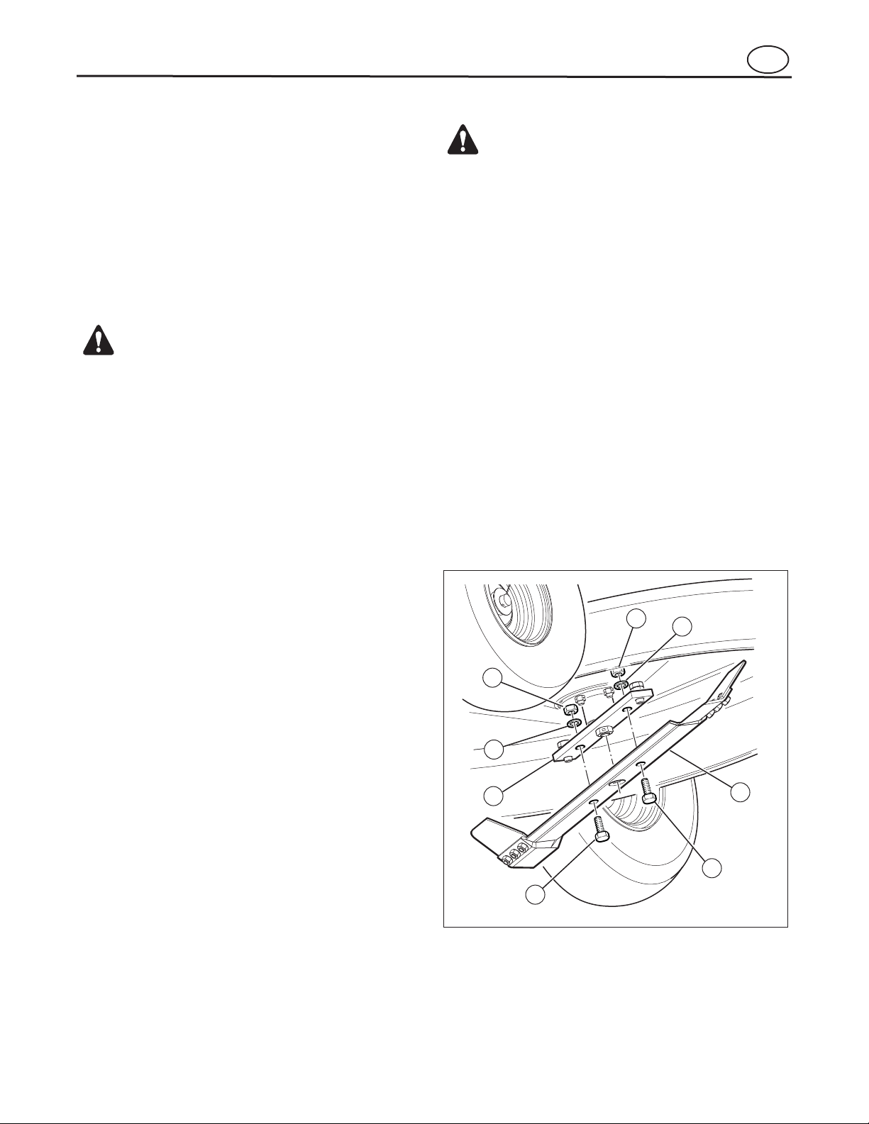
Remove and Install the Blade
WARNING
Before you inspect or remove the blade, disconnect
the wire to the spark plug. If the blade hits an
obj
ect, stop the engine. Check the unit for damage.
The blade has sharp edges. When you hold the
blade, use gloves or cloth material to protect your
hands.
Check the Blade Rotation Control
WARNING
To prevent an injury, the blade rotation control must
operate correctly.
Figure 8
Figure 9
Figure 18
Check and Adjust the Clutch
WARNING
Before you make an inspection, adjustment, or
repair to the unit, disconnect the wire to the spark
plug. Remove the wire from the spark plug to
prevent the engine from starting by accident.
Figure 22
Figure 22
Figure 21
en
1. Remove the mower deck. See the instructions
to “Remove and Install the Mower Deck”.
2. Use a piece of wood to keep the blade from
rotating.
3. Remove the nuts (2), washers (3), and bolts (4)
that hold the blade (1) (see F
4. Check the blade according to the instructions for
“Inspect Blade”. Replace a badly worn or damaged
blade with an original equipment blade. See an
authorized service center in your area.
5. Clean the top and bottom of the mower deck.
Remove all the grass and debris.
6. Mount the blade on the mandrel (5).
7. Mount the blade so that the hi-lift edges are up. If
the blade is upside down, the blade will not cut
correctly and can cause an accident.
8. Fasten the blade with the original bolts (4), washers (3), and nuts (2).
9. Tighten the nuts that hold the blade to 30 ft-lbs
(41,5 Nm).
10. Install the mower deck. See “Remove and Install
the Mower Deck”.
).
5. Check the blade(s). Keep a sharp edge on the
blade(s). A blade that is not sharp will cause the
tips of the grass to become brown.
6. If the quality of cut has not improved, replace the
mower drive belt. See “Remove and Install the
Mower Drive Belt”. If replacing the belt does not
correct the problem, take the unit to an authorized
service center.
7. When you move the blade rotation control to the
DISENGAGE position, all movement will stop
within five seconds. If there is movement of the belt
or the blades continue to rotate, engage and disengage the blade rotation control five times to
remove any excess rubber from a new mower drive
belt. If you need assistance, take the unit to an
authorized service center.
If the motion drive belt is loose, the clutch will slip when
going up a hill, pulling a heavy load, or the unit will not
move forward. Adjust the clutch as follows.
1. Check the routing of the motion drive belt. Make
sure the belt is installed correctly and is inside all
the belt guides.
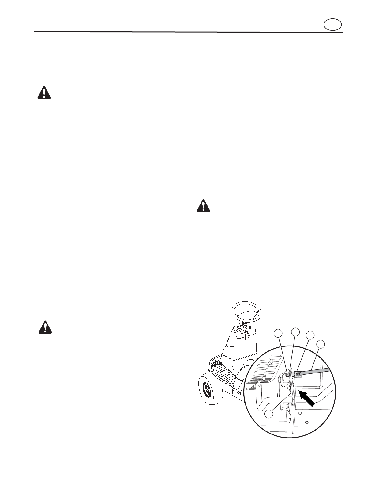
2. Remove the cotter pin (1) and washer (2) from the
adjustable nut (3) (see F
).
In normal usage, the blade rotation control will not require an adjustment. However, if the cutting performance decreases or the quality of cut is poor, make the
following changes.
1. When you mow, make sure the throttle control is in
the FAST position (see F
2. Move the blade rotation control to the DISENGAGE position (see F
3. Turn the ignition switch to the OFF positon to stop
the engine (see F
4. Disconnect the wire from the spark plug.
24
).
).
).
2
1
4
3
5
Page 25
WARNING
If you cannot correctly adjust the drive brake,
replace the brake pads. Correct replacement parts
and assistance are available from an authorized
service center.
Maintenance
Check and Adjust the Drive Brake
Figure 23
Figure 15
B, Figure 12
Figure 23
Figure 6
Remove the Battery
WARNING
To prevent sparks, fasten the red cable to the
positive (+) terminal before you connect the
negative (-) black cable.
WARNING
The battery contains surphuric acid which is harmful to the skin, eyes and clothing. If the acid gets on
the body or clothing, wash with water.
en
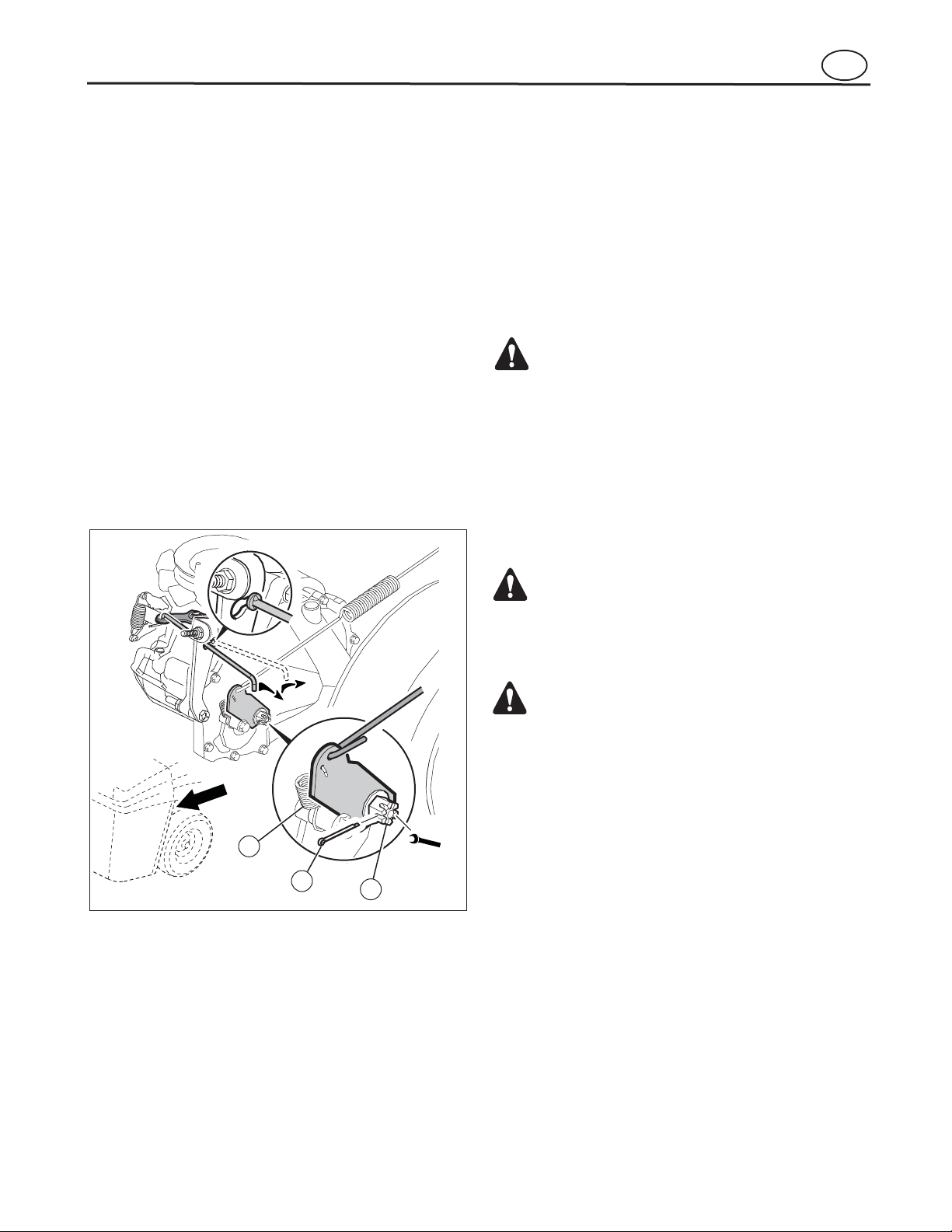
3. Disconnect the adjustable nut (3) from the brake
lever (4).
4. Align the hole in the brake lever to be 1/4 inch from
the rear of the slot in the frame.
5. Push the clutch rod (5) toward the rear. Turn the
adjustable nut until the nut will fit through the hole
in the brake lever.
6. Assemble the adjustable nut to the brake lever.
7. If the belt still slips after the clutch has been adjusted, then the motion drive belt is worn or damaged and must be replaced. See “Remove and
Install the Motion Drive Belt”.
1. The location of the drive brake is on the right side
of the gear box (see F
2. Make sure the parking brake is set (F
and the automatic drive disconnect is in the PUSH
position (see B
).
).
)
c. Insert a 0.020 in. feeler gauge between the
brake rotor and top brake puck, then set the
brake by finger tightening or loosening the
castle nut.
d. Install a new cotter pin to secure the castle
nut and then install the brake arm spring.
e. Engage the parking brake.
f. Push the unit. If the rear wheels do not turn,
the drive brake is correctly adjusted.
g. Release the parking brake.
To charge or clean the battery, remove the battery from
the unit as follows.
1
2
3. Push the unit. If the rear wheels rotate, adjust the
brake pads as follows:
a. Release the parking brake.
b. Remove the brake arm spring (1) and cotter
pin (2) that secures the castle nut (3).
9/16
3
W
1. Remove the two screws (1) and battery cover (2)
(see F
2. Disconnect the black cable (8) from the negative
(-) terminal.
3. Disconnect the red cable (6) from the positive (+)
terminal.
4. To disconnect the battery retainer (4), push in on
the lower end of the battery retainer.
5. Remove the battery (3) from the opening between
the engine and the seat support.
).
25
Page 26
Maintenance
WARNING
To prevent sparks, fasten the red cable to the
positive (+) terminal before you connect the
negative (-
) black cable.
Level the Mower Deck
WARNING
Before you make an inspection, adjustment, or
repair to the unit, disconnect the wire to the spark
plug. Remove the spark plug wire to prevent the
engine from starting by accident.
Figure 25
2
1
4
3
Figure 6
WARNING
When you charge the battery, do not smoke. Keep
the battery away from any sparks. The fumes from
the ba
ttery acid can cause an explosion.
Charge the Battery
Figure 24
Figure 25
Figure 26
Figure 26
4
1
3
2
Figure 24
1. Before you charge the battery (3), remove the
battery (see F
2. To charge the battery, use a 12 volt battery
charger. Charge at a rate of 6 amps for 1 hour.
If you do not have a battery charger, have an authorized service center charge the battery.
3. Install the battery.
).
4. Connect the red cable (6) to the positive (+) termnal using the fasteners (7).
5. Connect the black cable (8) to the negative (-)
terminal with the fasteners (7).
6. Connect the battery retainer (4).
7. Install the battery cover (2) using two screws (1).
en
1
40
2
20
60
0
14 PSI
(0,97 BAR)
10 PSI
(0,69 BAR)
If the mower deck is level, the blade will cut easier and
the lawn will look better.
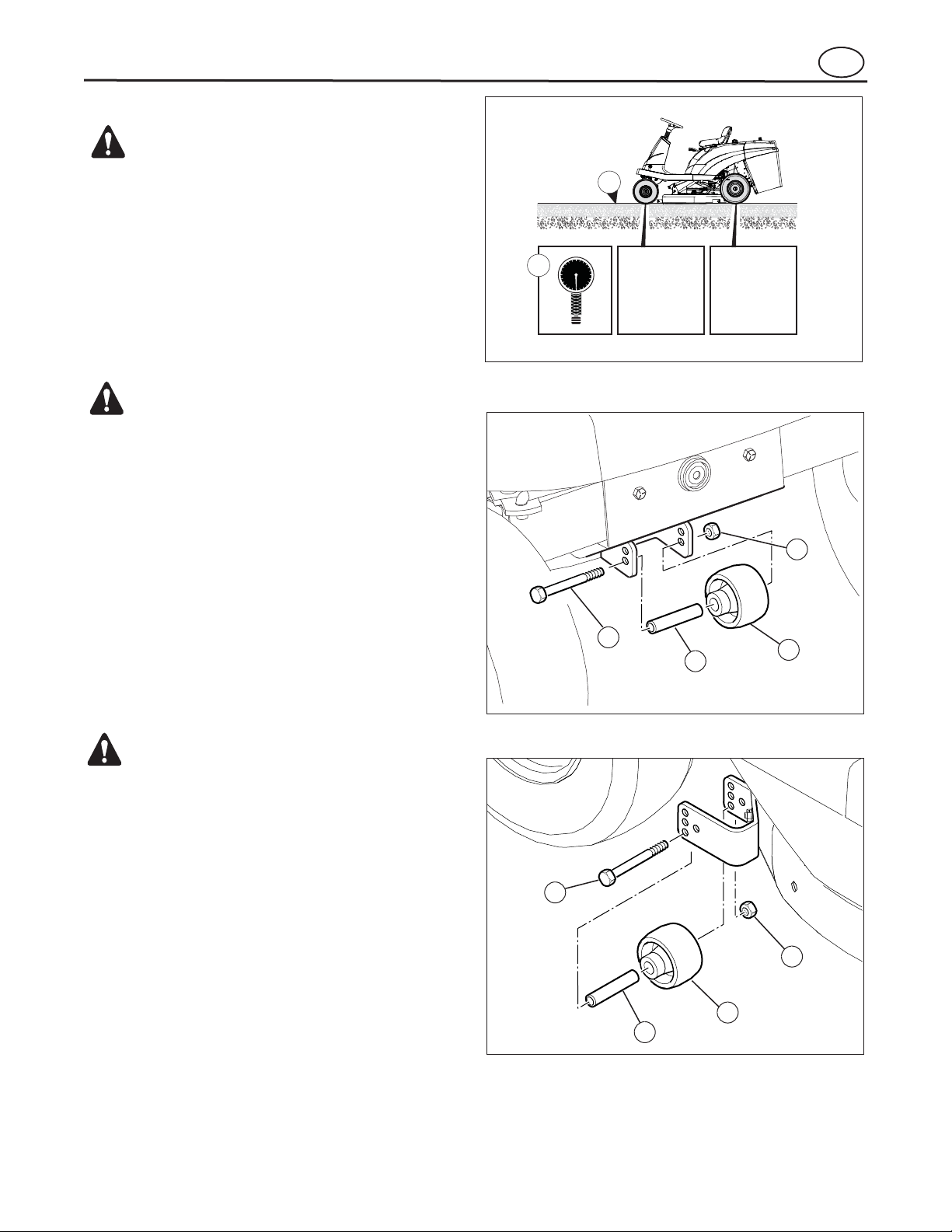
1. Make sure the unit is on a hard flat surface (1) (see
2. Check the air pressure in the tires (2). If the air
pressure is incorrect, the mower deck will not cut
level. Make sure the tires are inflated to: Front Tires
0,97 BAR (14 PSI), Rear Tires 0,69 BAR (10 PSI).
3. Remove the one gauge wheel from the front of the
mower deck (F
in the rear of the mower deck (F
).
) and the two gauge wheels
).
26
Page 27

Maintenance
Figure 16
A and B
Figure 27
C, Figure 27
Figure 27
D and E, Figure 27
en
4. Move the lift lever to the low cut position (see
5. Disconnect the lift links from the rear of the mower
deck (see A
6. Lower the mower deck to rest on the hard flat surface.
7. Remove the hair pin and adjusting nut from the
front bracket assembly (see C
).
, F
A
).
).
8. Adjust link until the adjusting nut fits into the hole
on the front bracket assembly.
9. Assemble washer and hair pin.
10. Reattach rear lift links (see D
D
).
D
A
C
C
B
EB
E
27
Page 28
Maintenance
Adjust the Gauge Wheels
IMPORTANT: Before you adjust the gauge wheels, you
must do the following. Make sure the mower deck is
l
evel. Make sure the height of cut is set at the height
you want for your lawn. Mow a short distance on a flat
level area and look at the area that was cut. If the
mower deck does not cut level, see the ins
tructions
“Level the Mower Deck.”
WARNING
Before you make an inspection, adjustment, or
repair to the unit, disconnect the wire to the spark
plug
. Remove the spark plug wire to prevent the
engine from starting by accident.
Figure 25 and 26
Figure 16
Figure 29 and Table below
Figure 28
A,
Figure 28
B, Figure 28
Figure 25 and 26
BA
< 1/4˝
< 6 mm
A A
B B
< 1/4˝
< 6 mm
Figure 29
en
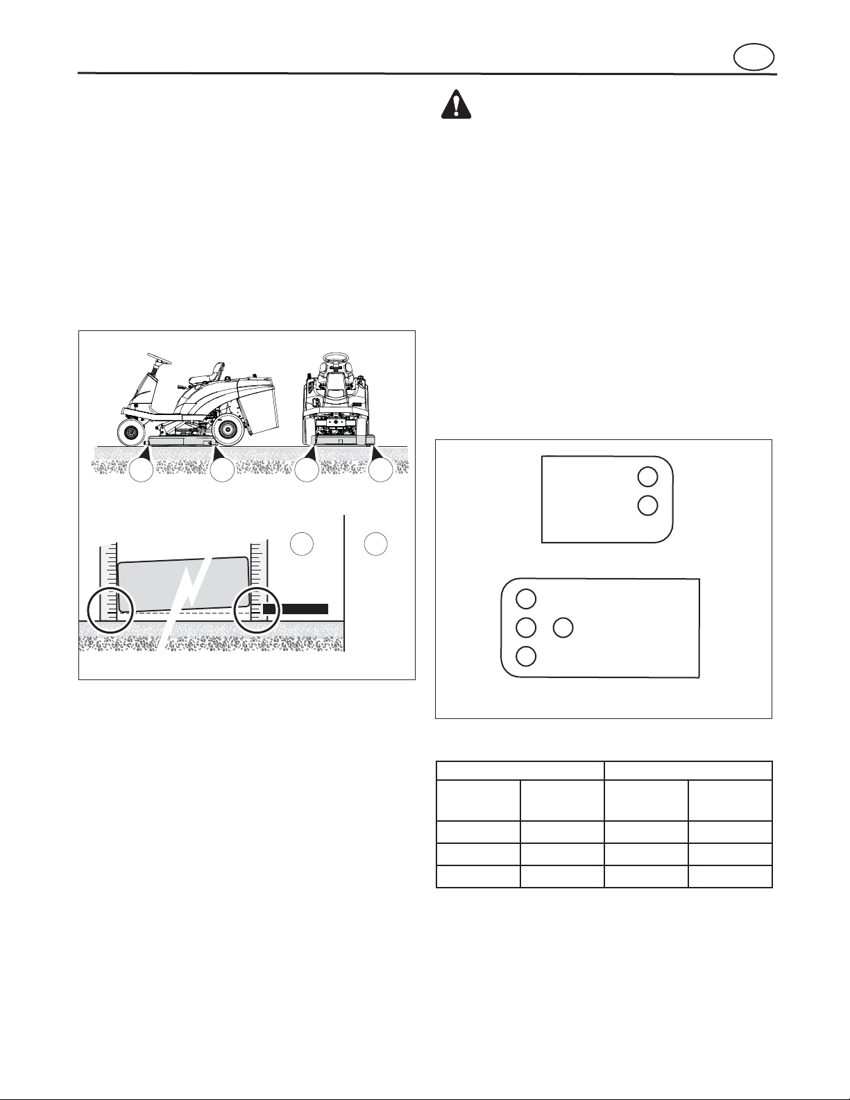
10. Measure the distance from the surface to the bottom of the mower deck in the front and rear. The
measurements should be within 1/4 in. (see A
11. Measure from the surface to the bottom of the
mower deck on the left and right.
a. The measurements should be within 1/4 in.
b. If not, remove the left lift link and adjust until
12. Reassemble the gauge wheels to the mower deck
brackets (see F
). If not, repeat Steps 4 through 10.
(see B
the measurements are within 1/4 in.
).
).
1. Remove the nut (1), bolt (2), sleeve (3), and gauge
wheel (4) from bracket (see F
2. Place lift lever in the desired height of cut setting
(see F
3. Mow a short distance on a flat area to check the
level of cut.
4. Assemble gauge wheels in the hole on the gauge
wheel bracket that positions the gauge wheel closest to the ground without touching the ground (see
5. Secure the gauge wheel (4), sleeve (3), and bolt
(2) on bracket with nut (1).
).
).
1
).
2
Front Wheel Bracket
1
2
3
Rear Wheel Bracket
Front Wheel Rear Wheels
Bracket Hole
Number
1 1,2,3 1 1
2 4,5,6 2 2
Lift Lever
Position
Bracket Hole
Number
3 4,5,6
Lift Lever
Position
28
Page 29
Maintenance
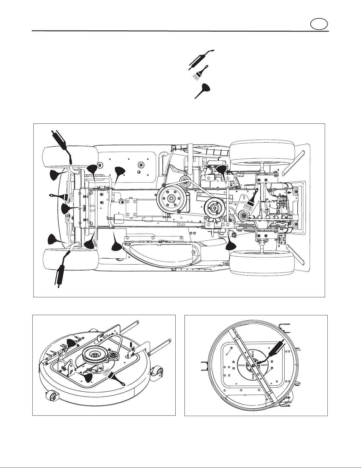
Lubrication
Figure 32. Arbor Lubrication Points
Figure 31. Mower Deck Lubrication Points
Figures 30
to 32
Figure 30. Tractor Lubrication Points
Models with grease fittings:
Lubricate with grease gun.
Lubricate the areas shown
with engine oil.
Apply grease with a brush
to areas shown.
en
Lubricate the unit at the locations shown in F
as well as the lubrication points listed.
• Generally, all moving metal parts should be oiled
where contact is made with other parts.
• Keep oil and grease off belts and pulleys.
• Wipe surfaces clean before and after lubrication.
NOTE: Use grease fittings when present. Automotive lithium grease is recommended.
29
Page 30
Maintenance
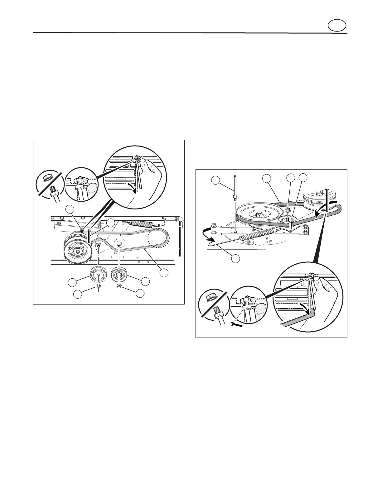
Remove and Install the Motion Drive Belt
Figure 33
Figure 34
Figure 33
Remove and Install the Mower Drive Belt
Figure 34
NOTE: Replace the mower drive belt with an original
equipment belt from an authorized service center.
2
1
2
1
5
3
4
1/2
2
4
3
5
1
en
1. Remove the mower deck. See the instructions to
“Remove and Install the Mower Deck”.
2. Completely push the pedal forward and engage
the parking brake.
3. Remove the nuts (1) and idler pulleys (2) (see
4. Loosen the belt guides (3) and (4) from the stack
pulley.
5. Remove the motion drive belt (5) from the drive
pulley and stack pulley.
).
1. Remove the mower deck. See the instructions to
“Remove and Install the Mower Deck”.
2. Disconnect the extension spring (1) from the
mower deck post.
3. Loosen the belt guide (2) from the drive pulley
(see F
4. Remove the flange nut (3) from the top of the idler
pulley (4) and remove the idler pulley.
5. Remove the mower drive belt (5).
6. A correct replacement part or assistance is available from an authorized service center.
).
6. A correct replacement part or assistance is available from an authorized service center.
7. Reverse the above steps to install the motion drive
belt.
8. Check the routing of the motion drive belt. Make
sure the motion drive belt is installed correctly on
the idler pulley. Make sure the motion drive belt is
inside all the belt guides.
9. Before you use the unit, check the adjustment of
the clutch. See the instructions to “Check and Adjust the Clutch”.
10. Install the mower deck. See the instructions to
”Remove and Install the Mower Deck”.
30
7. Reverse the above steps to install the mower drive
belt.
8. Install the mower deck. See the instructions to
“Remove and Install the Mower Deck”.
9. Before you mow, check the blade rotation control.
Page 31

Maintenance
Remove and Install the Mower Deck
Figure 35
A, Figure 35
B and C, Figure 35
Figure 35
1. Move the blade rotation control (1) to the DISENGAGE position (see F
2. Move the lift lever (2) to the low cut position.
3. Remove the hair pins (5) and washers (6) from the
rear suspension arms (see A
4. Remove the hair pins (7) and washers (8) from the
suspension links (see B
5. Disconnect the front hanger (9) from the frame
support.
6. Disconnect the extension spring (10) from the
mower deck post.
1
).
2
).
).
en
7. Loosen the belt guide (11) from the stack pulley.
8. Remove the mower drive belt (12) from the engine
pulley.
9. Pull the mower housing away from the right side of
the unit.
10. To operate the unit without the mower deck, move
the lift lever to the TOP position.
11. Reverse the above steps to install the mower deck.
12. Make sure the blade drive belt is inside all the belt
guides.
8
7
B
10
1/2
12
11
7
8
5
6
C
A
B
9
A
31
Page 32

Maintenance
Install the Wheels
Front Wheel
Figure 36
1
2
4
1
2
6
5
9
8
7
Figure 37
1
2
3
7
4
6
5
Figure 36
Rear Wheel
Figure 37
Bag Full Indicator Adjustment
Figure 38
NOTE: It may be necessary to change the bag full indicator adjustment as turf conditions change.
1
2
Figure 38
en
If the wheels must be removed for service, make sure
they are installed as follows:
1. Make sure the valve stem (1) is to the outside (see
2. Slide the front wheel (2) onto the spindle (3).
3. Fasten the front wheel (2) with washers (4 and 5)
and cotter pin (6). Bend the ends of the cotter pin
apart to keep the front wheel on the spindle.
4. If your model has hub caps (7), install the hub
caps. Make sure the washers hold the hub caps in
place.
).
1. Install the washers (1) and spacer (2) onto the axle
(3) (see F
).
2. Mount the square key (4) in the key slot.
3. Make sure the valve stem (5) is to the outside.
4. Align the slot in the rear wheel with the square
key.
5. Slide the rear wheel (6) onto the axle (2).
6. Fasten the rear wheel (6) with washer (7) and
e-ring (8).
7. If your model has hub caps (9), install the hub
caps. Make sure the washer holds the hub caps
in place.
Sliding the carriage bolt, washer, and nut (1) up decreases the sensitivity in the bagger before the buzzer
goes off (see F
). Sliding the carriage bolt,
washer, and nut down increases the sensitivity in the
bagger before the buzzer goes off.
1. Loosen carriage bolt, washer, and nut (1).
2. Slide carriage bolt, washer, and nut up or down the
buzzer lever (2).
3. Tighten carriage bolt, washer, and nut.
32
Page 33

Storage (over 30 days)
Order Replacement Parts
www.BRIGGSandSTRATTON.com.
www.BRIGGSandSTRATTON.com
Maintenance
Replace the Fuse
Bagger Cover Adjustment
NOTE: The bagger cover should come properly adjusted from the factory.
Figure
39
Figure 39
en
1. Check the alignment of the plastic bagger cover
with the rear trim of the body.
2. If necessary, adjust the bagger cover by tightening
or loosening the bolts at the rear plate (see F
). Tightening the bolt will move the bagger cover
closer to the rear trim and loosening will increase
the space between the parts.
If the fuse is blown, the engine will not start.
Remove the fuse and replace with a 15 amp
automotive fuse.
At the end of each year, prepare the unit for storage as
follows.
1. Drain the fuel from the carburetor and the fuel
tank. Change the engine oil. See the engine
manufacturer’s instructions.
2. Clean the entire unit.
3. Charge the battery.
The replacement parts are shown either on the back
pages of this Operator’s Manual or in a separate Illustrated Parts List (IPL) catalog.
Use only manufacturer’s authorized or approved replacement parts. Do not use attachments or accessories not specifically recommended for this unit. In
order to obtain proper replacement parts you must
supply the model number of your mower (see nameplate).
Replacement parts, except for the engine, transmission, transaxle or differential, are available from the
store where the mower was purchased or a service
shop recommended by the store.
Warranty service is available only through Authorized
Service Dealers. Locate your nearest dealer in our
dealer locator map at
Replacement parts for the engine, transaxle, or transmission, are available from the manufacturer’s authorized service center found in the commercial pages of
the telephone directory. Also, see the individual engine
or transmission warranties to order replacement parts.
When ordering the following information is required:
(1) Model Number
(2) Serial Number
(3) Part Number
(4) Quantity.
If you are not able to get parts or service in the manner
given above, then contact:
Briggs & Stratton UK Ltd
Road Four, Winsford Industrial Estate
Winsford, Chesire
CW7 3QN
33
Page 34

Troubleshooting Chart
Problem Solution
The engine will not start. 1. Follow the steps, “Start the Engine” in this book.
2. Clean the battery terminals. Tighten the cables.
3. Check for a loose wire. Tighten the limit switches. (See the wiring
diagram.)
4. Drain the fuel tank. Clean the fuel line. Replace the fuel filter.
5. Remove the spark plug(s). Move the throttle to the SLOW position.
Turn the ignition key to the ON position. Try to start the engine
several times. Install the spark plug.
6. Replace the spark plug.
7. Adjust the carburetor.
The engine will not turn over. 1. Follow the steps, “To Start the Engine” in this book.
2. Charge the battery.
3. Replace the fuse.
4. Check the wiring harness for damage or a loose connection. Repair
the damaged wire.
5. Replace the solenoid.
en
The engine is difficult to start. 1. Adjust the carburetor.
2. Replace the spark plug.
3. Replace the fuel filter.
The engine does not run smooth or has a
loss of power.
The engine does not run smooth at fast speed. 1 Replace the spark plug.
The engine stops when the blades are
engaged.
1. Check the oil.
2. Clean the air filter.
3. Clean the air screen.
4. Replace the spark plug.
5. The engine is working too hard. Use a lower gear.
6. Adjust the carburetor.
7. Replace the fuel filter.
2. Adjust the throttle control.
3. Clean the air filter.
4. Replace the fuel filter.
1. Check the wiring harness for damage or a loose connection. Repair
the damaged wire.
2. Grass bag must be installed (applies only to model with rear
discharge grass bag).
On slopes, the engine stops. 1. Mow up and down slopes. Never mow across a slope.
34
Page 35

Troubleshooting Chart
Problem Solution
The engine will not idle. 1. Replace the spark plug.
2. Clean the air filter.
3. Adjust the carburetor.
4. Adjust the throttle control.
5. Drain the fuel tank. Clean the fuel line. Replace the fuel filter.
A hot engine causes a decrease in power. 1. Clean the air screen.
2. Check the oil.
3. Adjust the carburetor.
4. Replace the fuel filter.
Excessive vibration. 1. Replace the blade.
2. Check for loose engine bolts.
3. Decrease the air pressure in the tires.
4. Adjust the carburetor.
5. Check for a damaged belt or damaged pulley. Replace the damaged
parts.
The grass does not discharge correctly. 1. Stop the engine. Clean the mower housing.
en
2. Raise the height of cut.
3. Replace or sharpen the blade(s).
4. Move the shift lever to a lower speed.
5. Move the throttle control to the FAST position.
6. Replace the spring for the blade idler.
7. Clean the extension tube and the connector tube (applies only to
model with rear discharge grass bag).
The mower housing does not cut level. 1. Check the air pressure in the tires.
2. Adjust the level of the mower housing.
3. Check the front axle. If the front axle does not freely pivot, loosen
the axle bolt(s).
The mower blades will not rotate. 1. Check the mower drive belt. Make sure the belt is installed correctly.
2. Replace the mower drive belt.
The unit will not move when the clutch is
engaged.
1. Check the motion drive belt. Make sure the belt is installed correctly.
2. Adjust the clutch.
3. Replace the motion drive belt.
The unit moves slower or stops when the
clutch is engaged.
1. Adjust the clutch.
2. Replace the motion drive belt.
35
Page 36

Troubleshooting Chart
Problem Solution
en
The unit will not move when the brake is
released and the speed control pedal is
depressed.
The unit moves slower or stops when the
clutch is engaged.
The unit moves slower or stops when the
speed control pedal is depressed.
When the clutch/brake pedal is released, belt
noise can be heard.
The rear wheels spin over uneven terrain. 1. Check the front axle. If the front axle does not freely pivot, loosen the
The transaxle is difficult to shift between
gears with the engine running and the clutch
depressed.
1. Check the motion drive belt. Make sure the belt is installed correctly.
2. Adjust the clutch.
3. Replace the motion drive belt.
4. Release the Automatic Drive Disconnect under the seat.
1. Adjust the clutch.
2. Replace the motion drive belt.
1. Adjust the clutch.
2. Replace the motion drive belt.
1. Temporary belt noise does not change the operation of the unit. If
belt noise is continuous, check the routing of the belt. Make sure the
belt is inside all belt guides.
2. If the noise is continuous, adjust the clutch.
axle bolt(s).
1. Check the clutch adjustment to make sure the belt stops when the
clutch pedal is depressed with the transaxle in (N) neutral.
2. Check the belt guides around the transaxle drive pulley. Make sure
the belt guides do not touch the pulley.
36
Page 37

en
BRIGGS AND STRATTON POWER PRODUCTS GROUP, L.L.C. OWNER WARRANTY POLICY
Effective January 1, 2008 replaces all undated Warranties and all Warranties dated before January 1, 2008
LIMITED WARRANTY
www.simplicitymfg.com
www.snapper.com
WARRANTY TERMS
Consumer Commercial
Brand / Unit Use Use
ABOUT YOUR WARRANTY
Normal Wear:
Installation:
Improper Maintenance:
Incorrect and/or Insufficient Fuel or Lubrication:
Operational Misuse:
Routine Tune-Up, Wear Items, or Adjustments:
Other Exclusions:
www.simplicitymfg.com
www.snapper.com
Briggs & Stratton Power Products Group, LLC will repair or replace, free of charge, any part(s) of the product that is defective in material or workmanship or
both. Transportation charges on product submitted for repair or replacement under this warranty must be borne by purchaser. This warranty is effective for
the time periods and subject to the conditions stated below. For warranty service, find the nearest Authorized Service Dealer in our dealer locator map at
THERE IS NO OTHER EXPRESS WARRANTY, IMPLIED WARRANTIES, INCLUDING THOSE OF MERCHANTABILITY AND FITNESS FOR A PARTICULAR PURPOSE, ARE LIMITED TO ONE YEAR FROM PURCHASE, OR TO THE EXTENT PERMITTED BY LAW. ANY AND ALL IMPLIED WARRANTIES
ARE EXCLUDED. LIABILITY FOR INCIDENTAL OR CONSEQUENTIAL DAMAGES ARE EXCLUDED TO THE EXTENT EXCLUSION IS PERMITTED BY
LAW. Some states or countries do not allow limitations on how long an implied warranty lasts, and some states or countries do not allow the exclusion or
limitation of incidental or consequential damages, so the above limitation and exclusion may not apply to you. This warranty gives you specific legal rights
and you may also have other rights which vary from state to state or country to country.
Ri ders / Tractors . . . . . . . . . . . . . . . . . . . . . . . . . . . . . . . 2 yea rs . . . . . . . . . . . . . . . . . . . . 90 days
The warranty period begins on the date of purchase by the first retail consumer or commercial end user, and continues for the period of time stated above.
“Consumer use” means personal residential household use by a retail consumer. “Commercial use” means all other uses, including use for commercial, income producing or rental purposes. Once product has experienced commercial use, it shall thereafter be considered as commercial use for purposes of
this warranty.
No warranty registration is necessary to obtain warranty on Simplicity/Snapper branded products. Save your proof of purchase receipt. If you do not provide
proof of the initial purchase date at the time warranty service is requested, the manufacturing date of the product will be used to determine the warranty.
We welcome warranty repair and apologize to you for being inconvenienced. Any Authorized Service Dealer may perform warranty repairs. Most warranty
repairs are handled routinely, but sometimes requests for warranty service may not be appropriate. For example, warranty service would not apply to the
product if damage occurred because of misuse, lack of routine maintenance, shipping, handling, warehousing or improper installation. Similarly, the warranty is void if the serial number on the product has been removed or the product has been altered or modified.
or w
.
This warranty covers product related defective material and/or workmanship only. To avoid misunderstanding which might occur between the customer and
the Dealer, listed below are some of the causes of product failure that the warranty does not cover.
•N
cover repair when normal use has exhausted the life of the product or part.
•I
installations that prevent starting cause unsatisfactory engine performance.
•I
nance and adjustment intervals are stated in the Operator’s Manual. Often product, such as tillers, edgers, rotary mowers, are used in dusty or dirty
conditions, which can cause what appears to be premature wear. Such wear, when caused by dirt, dust, or other abrasive material entering the product because of improper maintenance is not covered by warranty. The warranty will not cover repairs due to problems caused by replacement parts
that are not original manufactured part(s).
•I
engine or engine components i.e., combustion chamber, valves, valve seats, valve guides, burned starter motor windings caused by use of alternate
fuels such as liquefied petroleum, natural gas, are not covered unless engine is certified for this operation. Parts which are scored or broken because
product was operated with insufficient, contaminated or incorrect grade of lubricating oil as well as product components damaged due to lack of lubrication are not covered.
•O
in a confined area without sufficient ventilation. Product broken by excessive vibration caused by a loose engine mounting, loose or unbalanced
blades, impellers, overspeeding, or bent crankshaft due to striking of solid object. Damage or malfunctions resulting from accidents, abuse, or improper servicing or freezing or chemical deterioration, as well as operating in excess of recommended capacities as outlined in the Operator’s Manual
are not covered.
•R
•O
spective manufacturers. This warranty excludes failures due to acts of God and other major forceful events beyond the manufacturer’s control.
Also excluded are used, reconditioned, and demonstration products.
Small Engine Powered Equipment, like all mechanical devices, needs periodic parts and service to perform well. Warranty does not
This warranty does not apply to product that has been subjected to improper or unauthorized installation, alteration or modification. Nor
The life of this product depends upon the conditions under which it operates, and the care it receives. Recommended mainte-
This warranty does not cover damage caused by the use of stale fuel, or altered gasoline. Damage to
Proper operation of the product is stated in the Operator’s Manual. Product damaged by overspeeding, overheating, or operation
This warranty excludes wear items such as oil, belts, blades, o-rings, filters, etc.
Repair or adjustments for part(s) that are not manufactured by Briggs & Stratton Corporation, are not covered, see warranty for re-
Warranty service is available only through Authorized Service Dealers. Locate your nearest dealer in our locator map at w
.
or
37
Page 38

38
Page 39

Premium Rider (CE)
BETRIEBSANLEITUNG
Handbuch-Teile-Nr. 885193
ACHTUNG: Alle Anweisungen
lesen und befolgen.
15,5 PS Traktoren mit 17,5 PS Traktoren mit
Hydrostatikgetriebe Hydrostatikgetriebe
Hst.-Nr. Beschreibung Hst.-Nr. Beschreibung
1
7800352 Snapper LT75 7800356 Snapper LT75
7800353 Snapper LT75 7800357 Snapper LT75
7800354 Simplicity Coronet 7800358 Simplicity Coronet
7800355 Simplicity Coronet 7800359 Simplicity Coronet
Rev.-Datum 01/2009
Revision A
Page 40

2
Page 41

Informationen für den Eigentümer . . . . . . . . . . . . . . . . . . . . . . . . . . . . . . . 4
Sichere Betriebspraktiken. . . . . . . . . . . . . . . . . . . . . . . . . . . . . . . . . . . . . . 5
Sicherheits- und Bedienungsaufkleber . . . . . . . . . . . . . . . . . . . . . . . . . . . 7
Zusammenbau. .
. . . . . . . . . . . . . . . . . . . . . . . . . . . . . . . . . . . . . . . . . . . . . 9
Betrieb . . . . . . . . . . . . . . . . . . . . . . . . . . . . . . . . . . . . . . . . . . . . . . . . . . . . 13
Wartungstabelle. . . . . . . . . . . . . . . . . . . . . . . . . . . . . . . . . . . . . . . . . .
. . . 22
Wartung . . . . . . . . . . . . . . . . . . . . . . . . . . . . . . . . . . . . . . . . . . . . . . . . . . . 23
Fehlersuchtabelle . . . . . . . . . . . . . . . . . . . . . . . . . . . . . . . . . . . . . . . . . . . 34
Beschränkte Garantie . . . . . . . . . . . . . . . . . . . . . . . . . . . . . .
. . . . . . . . . . 37
Technische Daten des Produkts . . . . . . . . . . . . . . . . . . . . . . . . . . . SPEC-1
Inhaltsverzeichnis
de
3
Page 42

Informationen für den Eigentümer
VORSICHT
Dieses Symbol weist auf wichtige Sicherheitsvorkehrungen hin. Diese Symbol bedeutet:
„Achtung! Seien Sie aufmerksam! Es geht um Ihre
Sicherheit.“
Machen Sie sich mit dem Produkt vertraut
Verantwortung des Eigentümers
VORSICHT
Diese Mähmaschine kann Gliedmaßen abtrennen
und Objekte auswerfen. Wenn die folgenden
Sicherheitsanweisungen nicht beachtet werden,
kann es zu schweren oder tödlichen Verletzungen
des Benutzers oder von Umstehenden kommen.
Der Benutzer ist dafür verantwortlich, die Anweisungen
in diesem Handbuch zu befolgen.
de
Wenn Sie die Maschine und deren Funktionsweise
verstehen, erhalten Sie die beste Leistung. Vergleichen
Sie beim Lesen dieses Handbuchs die Abbildungen
mit der Maschine. Machen Sie sich mit der Lage und
Funktionsweise der Bedienelemente vertraut. Um
Unfälle zu vermeiden, müssen die Bedienungsanweisungen und Sicherheitsvorschriften befolgt
werden. Heben Sie dieses Handbuch zum späteren
Nachschlagen auf.
4
Page 43

Sichere Betriebspraktiken
Einweisung
Für Aufsitzmäher mit Drehmesser
Vorbereitung
WARNUNG - Kraftstoff ist leicht entzündbar.
Betrieb
de
1. Die Anweisungen sorgfältig lesen. Machen Sie
sich mit den Bedienelementen sowie der
ordnungsgemäßen Verwendung der Maschine
vertraut.
2. Niemals Kinder oder nicht mit diesen
Anweisungen vertraute Personen die Benutzung
der Maschine erlauben. Örtliche Vorschriften
können ein Mindestalter für den Betreiber
vorschreiben.
3. Niemals mähen, wenn Personen, besonders
Kinder oder Haustiere in der Nähe sind.
4. Der Bediener oder Benutzer ist für Unfälle oder
Gefahren verantwortlich, die anderen Personen
oder deren Eigentum entstehen.
5. Keine Mitfahrer erlauben.
6. Alle Fahrer müssen sich von einem Fachmann in
die Bedienung der Maschine einweisen lassen.
Diese Anweisungen müssen Folgendes
hervorheben:
a. Sorgfalt und Konzentration bei der Arbeit mit
Aufsitzmähern;
b. Die Kontrolle eines Aufsitzmähers, der an
einem Hang ins Rutschen kommt, kann nicht
durch Betätigen der Bremse wiedererlangt
werden. Hauptgründe für den Verlust der
Kontrolle sind:
• unzureichende Radhaftung;
• Fahrgeschwindigkeit ist zu hoch;
• unzureichendes Bremsen;
• Maschine ist für die Aufgabe nicht
geeignet;
• unzureichende Kenntnisse über die
Bodenverhältnisse, besonders Neigungen;
• unvorschriftsmäßiges Ankuppeln und
falsche Verteilung der Last.
1. Beim Mähen stets festes Schuhwerk und lange
Hosen tragen. Die Maschine nicht barfuß oder mit
Sandalen bedienen.
2. Den Arbeitsbereich vor Verwendung der Maschine
sorgfältig untersuchen und alle Objekte, die von
der Maschine weggeschleudert werden könnten,
entfernen.
3. W
a. Kraftstoff in speziell dafür vorgesehenen
Behältern aufbewahren.
b. Nur im Freien auftanken und beim Auftanken
nicht rauchen.
c. Kraftstoff vor dem Anlassen des Motors
nachfüllen. Niemals den Kraftstofftankdeckel
entfernen oder Kraftstoff nachfüllen, wenn der
Motor läuft oder während der Motor heiß ist.
d. Falls Kraftstoff verschüttet wurde, den Motor
nicht anlassen, sondern die Maschine aus der
Gefahrenzone bringen und von jeglichen
Zündquellen fernhalten, bis sich die
Kraftstoffdämpfe verflüchtigt haben.
e. Alle Kraftstofftank- und Behälterdeckel sicher
anbringen.
4. Defekte Schalldämpfer austauschen.
5. Vor dem Betrieb stets visuell prüfen, ob die
Mähmesser, Mähmesserschrauben und die
Schneidbaugruppe nicht abgenutzt oder
beschädigt sind. Abgenutzt oder beschädigte
Messer und Schrauben müssen in Sätzen
ausgetauscht werden, damit die Auswuchtung
erhalten bleibt.
6. Bei Mähern mit mehreren Mähmessern ist
besondere Vorsicht geboten, da sich beim Drehen
eines Mähmessers die anderen Mähmesser
mitdrehen können.
1. Den Motor nicht in einem geschlossen Raum
betreiben, in dem sich gefährliches
Kohlenmonoxidgas ansammeln kann.
2. Nur bei Tageslicht oder ausreichender künstlicher
Beleuchtung mähen.
3. Bevor versucht wird den Motor anzulassen,
müssen alle Messerkupplungen ausgekuppelt und
die Gangschaltung in die Leerlaufstellung gebracht
werden.
4. Die Maschine nicht an steilen Hängen mit mehr als
10 Grad Neigung verwenden.
5. Es gibt keine „sichere“ Hanglage. Aauf geneigten
Grasflächen muss äußerst vorsichtig gefahren
werden. Schutz gegen Überschlagen:
a. Beim Auf- oder Abwärtsfahren nicht plötzlich
stoppen oder anfahren;
b. Die Kupplung langsam eingreifen lassen,
immer einen Gang eingelegt haben,
besonders beim Abwärtsfahren;
c. Die Maschine muss an Hängen und in engen
Kurven langsam gefahren werden;
d. Auf Buckel und Löcher sowie andere
versteckte Gefahren achten;
e. Nie quer zum Hang mähen, es sei denn der
Mäher ist für diesen Zweck vorgesehen.
6. Beim Ziehen von Lasten oder bei der Benutzung
schwerer Ausrüstung vorsichtig sein.
a. Ausschließlich zugelassene
Anhängekupplungen verwenden.
b. Lasten auf solche beschränken, die sicher
unter Kontrolle gehalten werden können.
c. Keine scharfen Kurven fahren. Beim Fahren
des Traktors im Rückwärtsgang Vorsicht
walten lassen.
d. Die in der Betriebsanleitung vorgeschlagenen
Rad- und Gegengewichte benutzen.
5
Page 44

Sichere Betriebspraktiken
Wartung und Lagerung
de
7. Beim Überqueren von Straßen bzw. in der Nähe
von Straßen auf den Verkehr achten.
8. Die Mähmesser stoppen, bevor Flächen ohne
Gras überquert werden.
9. Bei Verwendung von Anbaugeräten den
Grasauswurf niemals direkt auf Umstehende
richten und den Zutritt zum unmittelbaren
Maschinenbereich während des Betriebs
untersagen.
10. Den Mäher nicht mit defekten oder bei fehlenden
Abdeckungen und Schutzvorrichtungen betreiben.
11. Die Einstellung des Drehzahlreglers nicht
verändern, den Motor nicht mit überhöhten
Drehzahlen betreiben. Der Betrieb des Motors mit
überhöhter Drehzahl kann die Verletzungsgefahr
erhöhen.
12. Bevor der Fahrersitz verlassen wird:
a. die Zapfwelle auskuppeln und die
Anbaugeräte absenken;
b. in den Leerlauf schalten und die
Feststellbremse anziehen;
c. den Motor abstellen und den Zündschlüssel
abziehen.
13. Mähwerkantriebe auskuppeln, Motor abstellen,
Zündkabel abklemmen oder Zündschlüssel
abziehen:
a. bevor Verstopfungen im Mähwerk oder
Auswurf beseitigt werden;
b. bevor der Mäher geprüft, gereinigt oder
gewartet wird;
c. nachdem ein Hindernis getroffen wurde. Den
Mäher anhalten und überprüfen, und
erforderliche Reparaturen vor der erneuten
Inbetriebnahme durchführen;
d. wenn die Maschine ungewöhnlich zu vibrieren
beginnt (sofort prüfen).
14. Beim Transport oder wenn nicht gemäht wird, die
Mähwerkantriebe auskuppeln.
15. Den Motor abstellen und den Mähwerkantrieb
auskuppeln:
a. bevor aufgetankt wird;
b. bevor die Grasfangvorrichtung entfernt wird;
c. bevor Höheneinstellungen vorgenommen
werden, es sei denn, diese können vom
Fahrersitz aus vorgenommen werden.
16. Beim Auslaufen des Motors das Gas
zurücknehmen; falls der Motor mit einem
Kraftstoffhahn ausgestattet ist, muss dieser nach
Abschluss der Mäharbeiten geschlossen werden.
17. Vor und während dem Rückwärtsfahren stets nach
hinten und unten schauen und auf kleine Kinder
achten.
18. Bei Annäherung an nicht einsehbare Ecken,
Sträucher, Bäume oder andere Objekte, die die
Sicht beeinträchtigen können, besonders
vorsichtig vorgehen.
1. Bei Mähern mit mehreren Mähmessern ist
besondere Vorsicht geboten, da sich beim Drehen
eines Mähmessers die anderen Mähmesser
mitdrehen können.
2. Wenn die Maschine abgestellt, gelagert oder
unbeaufsichtigt gelassen wird, das Mähwerk
absenken, sofern keine mechanische Verriegelung
verwendet wird.
3. Darauf achten, dass alle Muttern, Schrauben und
Bolzen fest angezogen und die Maschine in
sicherem Betriebszustand ist.
4. Niemals eine Maschine mit Kraftstoff im Tank in
einem Gebäude einlagern, wo Kraftstoffdämpfe
offenen Flammen oder Funken ausgesetzt sein
können.
5. Den Motor vor der Lagerung in geschlossenen
Räumen abkühlen lassen.
6. Zur Verminderung der Feuergefahr Motor,
Schalldämpfer, Batteriefach und Kraftstofftank von
Gras, Laub oder überschüssigem Schmierfett
freihalten.
7. Die Grasfangvorrichtung regelmäßig auf
Abnutzung oder Zustandsverschlechterung prüfen.
8. Verschlissene oder beschädigte Teile
sicherheitshalber ersetzen.
9. Den Kraftstofftank, sofern erforderlich, nur im
Freien entleeren.
6
Page 45

Sicherheits- und Bedienungsaufkleber
Aufkleber - Betriebsanleitung (CE)
(48x4032)
Aufkleber Feststellbremse
(48x726)
Aufkleber - Zündschalter
(1722806)
Aufkleber - Schnitthöhe
(885253)
Aufkleber - Rollenfreigabe
(1723425)
Aufkleber - Heiße
Oberfläch
e (885216)
Aufkleber Gashebel (885171)
Aufkleber - Auswurfschacht
(1721107)
Aufkleber Brandgefahr
(88521
8)
Aufkleber Bremse/Kupplung
(48x726)
Aufkleber Fahrgeschwindigkeitspedal
(885169)
Aufkleber - Zugstange
nlast
(48x5911)
Aufkleber - Geräuschpegel
(48x5911)
Typenschild
Aufkleber - Abtrenngefahr (885217)
de
Alle Sicherheits- und Bedienungsaufkleber müssen
gut durchgelesen und befolgt werden. Die
Nichteinhaltung der Anweisungen auf diesen
Aufklebern kann zu schweren Verletzungen und/oder
Sachschäden führen.
48x4032
HINWEIS: Fehlende oder beschädigte
Aufkleber/Schilder müssen unverzüglich ersetzt
werden. Den örtlichen Händler um Ersatzteile
aufsuchen.
_
(
)
LB
20
_
(
)
LB
34
7
Page 46

Sicherheits- und Bedienungsaufkleber
1
2
3
5
9
11
12
13
4
7
8
10
14
15
6
WICHTIG: Die folgenden Symbole befinden sich
auf der Maschine oder in der mit der Maschine
mitgelieferten Literatur. Vor dem Betrieb der
Maschine müssen Sie sich mit dem Zweck der
einzelnen Symbole vertraut
machen.
Sicherheitswarnsymbole
1
2
3
4
5
6
7
8
9
10
11
12
13
14
15
Bedienungs- und Betriebssymbole
1
2
3
4
5
6
7
8
9
10
11
12
1
2
3
4
5
6
7
8
9
10
11
12
de
VORSICHT.
WICHTIG: Vor Betrieb der Maschine die
Betriebsanleitung lesen.
VORSICHT: Ausgeworfene Gegenstände.
Umstehende Personen fernhalten. Vor
Betrieb dieser Maschine die
Betriebsanleitung lesen.
VORSICHT: Diese Maschine darf nicht auf
Abhängen mit mehr als 10° Steigung
betrieben werden.
GEFAHR: Personen, besonders Kinder von
der Maschine fernhalten.
GEFAHR: Vom Mähmesser fernbleiben,
solange der Motor läuft.
GEFAHR: Hände und Füße vom drehenden
Messer fernhalten.
GEFAHR: Vor der Maschinenwartung das
Zündkabel von der Zündkerze abklemmen.
VORSICHT: Heiße Oberfläche.
VORSICHT: Beim Anschließen oder
Abtrennen von Zubehörteilen vorsichtig
sein.
VORSICHT: Quetschgefahr für Finger.
WICHTIG: Die Anweisungen in der
Betriebsanleitung zum Nivellieren des
Mähwerks befolgen.
GEFAHR: Vom Mähmesser fernbleiben,
solange der Motor läuft.
VORSICHT: Auswurfschacht. Nicht als
Grasfangvorrichtung benutzen, es sei denn
ein Auswurfschacht ist angebracht.
VORSICHT: Brandgefahr. Gartenmist ist
brennbar. Die Maschine frei von
Rückständen halten.
Motor anlassen
Motor abstellen
Motor läuft
Bremse
Feststellbremse
Kupplung
Langsam
Schnell
Choke
Öl
Mähmesserbedienknopf
Kraftstoff
8
Page 47

Baugruppe
NOTIZEN: Alle Befestigungsteile befinden sich im
Teilebeutel. Keine Teile oder Materialien wegwerfen,
bevor die Maschine fertig zusammengebaut ist.
Vor Montage- oder Wartungsarbeiten am Mäher muss
das Zündk
abel von der Zündkerze abgeklemmt
werden.
Einbau des Fahrersitzes
Abbildung 2
HINWEIS: Die Unterlegscheiben nur an der linken
Seite anbringen.
1
3
7
5
4
6
2
5
Abbildung 2
Einbau Sie die Vorderräder
Abbildung 1
1
2
3
7
4
6
5
Abbildung 1
de
1. Vergewissern Sie sich, dass der Ventilschaft (1)
zur Außenseite zeigt (siehe A
2. Schieben Sie das Vorderrad (2) auf die Spindel (3).
3. Befestigen Sie das Vorderrad (2) mit Unterlegscheiben (4 und 5) und Splint (6). Biegen Sie
die Enden des Splintes auseinander, um das
Vorderrad an der Spindel zu halten.
4. Falls Ihr Modell über Nabenkappen (7) verfügt,
installieren Sie die Nabenkappen. Vergewissern
Sie sich, dass die Unterlegscheiben die
Nabenkappen am Platz halten.
5. Wiederholen Sie dies für die gegenüberliegende
Seite.
).
1. Den Kunststoffbeutel sorgfältig vom Sitz entfernen.
2. Den Sitzsträger (1) anheben (siehe A
3. Die Löcher im Sitz (2) auf die Schlitze im Sitzträger
ausrichten.
4. Den Sitz (2) samt Einstellhebel (3) und mit
Unterlegscheiben (4) und Schrauben (5) auf dem
Sitzträger (1) anbringen.
5. Den Kabelbaum (6) am Sitzschalter (7) unter dem
Sitz anschließen.
).
6. Den Sitz in die normale Betriebsstellung
absenken.
7. Die Funktion der Sitzverstellung prüfen.
a. Falls der Sitz verstellt werden muss, den
Einstellhebel (3) in Richtung Sitz ziehen und
den Sitz in die gewünschte Position schieben.
b. Den Einstellhebel loslassen, um den Sitz in
der neuen Position zu arretieren.
9
Page 48

Abbildung 4
Baugruppe
Montieren Sie das Lenkrad
Abbildung 3
Abbildung 3
Abbildung 3
Grasfangsack anbringen
Abbildung 4
de
1. Vergewissern Sie sich, dass die Vorderräder nach
vorn zeigen wie in A
2. Schieben Sie die Balge (1, A
Konsole.
3. Schieben Sie die Lenksäule (2) in die Konsole.
7
3/8
4
5
1
3
gezeigt.
8
) über die
2
1. Das untere Rohr (1) auf den Grasfangrahmen (2)
schieben (siehe A
2. Die Löcher unten im Rohr auf die Löcher im
Grasfangrahmen ausrichten.
3. Die Splinte (3) in die Löcher schieben und
umbiegen, damit das Rohr am Rahmen gesichert
ist.
4. Die Rahmenbaugruppe auf den Grasfangsack (4)
schieben.
5. Die Sack-Clips an der Rahmenbaugruppe
befestigen.
6. Die Grasfangvorrichtungsabdeckung (5) auf die
Rahmenlöcher ausrichten.
7. Die Seite und den Oberteil der Abdeckung mit den
Schrauben (6) und (7) am Grasfangvorrichtungsrahmen befestigen.
8. Den Grasfangvorrichtungsgriff (8) durch das Loch
in der Abdeckung und im Rahmen einbauen.
9. Den Grasfangvorrichtungsgriff mit Unterlegscheibe
(9), Schraube (10) und Mutter (11) sichern.
10. Installieren Sie den Bügel des Grasfängers (12)
mit zwei Schrauben (13) an der Abdeckung.
).
6
4. Befestigen Sie das Lenkrad (3) mit der Schraube
(4) und Unterlegscheibe (5) an der Lenksäule (2).
Die Schrauben gut festziehen, aber nicht
überziehen.
a. Das Lenkrad aufdrücken. Die Lenksäule rastet
in im Zahngetriebe ein (6).
b. Ziehen Sie am Lenkrad. Vergewissern Sie
sich, dass die Lenksäule in Position
eingerastet ist.
5. Installieren Sie die Platte (7) und die Abdeckung
(8) am Lenkrad.
5/16
5
6
9
10
8
12
7
13
11
7/16
4
1
2
3
10
Page 49

Wartungsfreie Batterie
WICHTIG: Bevor die Batteriekabel an die Batterie
angeschlossen werden, muss das Batteriedatum
geprüft werden. Das Batteriedatum gibt an, ob die
Batterie geladen werden muss.
Abbildung 2
Abbildung
6
Baugruppe
Montieren Sie den Grasbeutel
Abbildung 5
Abbildung 5
Abbildung 6
de
1. Die Grasbeuteleinheit wie gezeigt an den Bügeln
des Grasfängers befestigen (siehe A
a. Mit einer Hand den Griff auf der Rückseite der
Beutelrahmeneinheit greifen.
b. Mit der anderen Hand den oberen Griff des
Grasfängers festhalten und die Beutelrahmeneinheit an den hinteren Klammern der
Grasfangeinheit entlang führen.
1
).
1. Den Sitzträger anheben (siehe A
2. Die zwei Schrauben (1) und die
Batterieabdeckung (2) entfernen (siehe A
).
3. Das Batteriedatum an der Batterieseitenwand (3)
ablesen.
a. Falls die Batterie vor diesem Datum in Betrieb
genommen wird, können die Batteriekabel
angeschlossen werden, ohne dass die
Batterie geladen werden muss. Siehe
„Batteriekabel anschließen“.
b. Falls die Batterie nach diesem Datum in
Betrieb genommen wird, muss die Batterie
geladen werden. Siehe „Batterie laden“.
2
).
1
2
2. Halten Sie den Boden der Grasfängereinheit beim
Montieren der Grasfängereinheit leicht von der
Rückplatte weg.
3. Drehen Sie die Grasbeuteleinheit so lange, bis sie
in Position einrastet.
4
3
7
5
6
8
11
Page 50

Baugruppe
Abbildung 6
Batterie laden
VORSICHT
Beim Aufladen der Batterie nicht rauchen. Offenes
Feuer und Funkenflug von der Batterie fernhalten.
Die
Dämpfe der Batteriesäure können eine
Explosion verursachen.
Batteriekabel anschließen
VORSICHT
Zur Vermeidung von Funken das rote Kabel am
Pluspol (+) anschließen, bevor das schwarze
Minuskabel (-) angeschlossen wird.
Abbildung 6
Motor vorbereiten
HINWEIS: Der Motor wurde mit Öl gefüllt aus dem
Werk ausgeliefert. Den Ölstand prüfen. Öl nach Bedarf
auffüllen.
VORSICHT
Die Anweisungen des Motorherstellers für die
benötigte Kraftstoff- und Ölsorte befolgen. Immer
einen sicheren Kraftstoffbehälter benutzen. Beim
Nachfüllen von Kraftstoff nicht rauchen. Nicht in
einem geschl
ossenen Raum auftanken. Vor dem
Auftanken den Motor abstellen. Den Motor mehrere
Minuten lang abkühlen
lassen.
Reifen prüfen
Mähwerknivellierung prüfen
Montieren Sie den Tankdeckel
de
1. Zum Abtrennen des Batteriehalters (4) am unteren
Ende des Batteriehalters andrücken (siehe
2. Die Batterie (3) aus der Öffnung zwischen Motor
und Sitzträger herausnehmen.
3. Die Schutzkappe von den Batteriepolen entfernen.
4. Die Batterie mit einem 12-V-Batterieladegerät
laden. Eine Stunden lang mit einer
Ladestromstärke von 6 A aufladen. Falls kein
Batterieladegerät verfügbar ist, die Batterie in einer
Vertragswerkstatt laden lassen.
5. Die Batterie einbauen. Sicherstellen, dass der
Pluspol (+) an der rechten Seite ist.
6. Den Batteriehalter anschließen.
).
1. Die Schutzkappen von den Batteriepolen
entfernen (siehe A
2. Die Polmanschette (5) auf das rote Kabel (6)
schieben.
3. Das rote Kabel mit den Befestigungsteilen (7) am
Pluspol (+) anschließen.
4. Das schwarze Kabel (8) mit den
Befestigungsteilen (7) am Minuspol (-)
anschließen.
5. Die Batterieabdeckung (2) mit den zwei
Schrauben (1) befestigen.
).
Den Luftdruck der Reifen prüfen. Reifen mit zu hohem
Luftdruck verursachen unruhiges Fahrverhalten.
Außerdem wird bei einem falschen Luftdruck nicht
waagrecht gemäht. Der korrekte Luftdruck:
Vorderradreifen 0,97 BAR (14 PSI), Hinterradreifen
0,69 BAR (10 PSI). Die Reifen werden mit überhöhtem
Luftdruck ausgeliefert.
Sicherstellen, dass der Schnitt noch immer stimmt.
Nachdem eine kurze Strecke gemäht wurde, die
gemähte Fläche ansehen. Falls das Mähwerk nicht
waagrecht schneidet, die Anweisungen unter
„Mähwerk nivellieren“ im Wartungsabschnitt dieses
Handbuchs nachschlagen.
In den Anweisungen des Motorherstellers die
benötigte Kraftstoff- und Ölsorte nachschlagen. Vor
Benutzung der Maschine die Informationen über
Sicherheit, Betrieb, Wartung und Lagerung lesen.
Der Tankdeckel wird im Zubehörteile-Beutel versandt,
und während des Transports wird die Tanköffnung mit
Klebeband verschlossen. Entfernen Sie vor dem
Betrieb das Klebeband vom Kraftstofftank und
installieren Sie den Tankdeckel.
12
Page 51

Betrieb
Anordnung der Bedienungselemente
Gashebel (1):
Abbildung 7
Kupplungs-/Bremspedal (2):
Zündschalter (3):
Feststellbremsenknopf (4):
Vorwärtsfahrgeschwindigkeitspedal (5):
1
2
3
4
5
6
7
8
10
9
11
Abbildung 7
Rückwärtsfahrgeschwindigkeitspedal (6):
Hubhebel (7):
Mähmesserbedienknopf (8):
Kraftstofftank (9):
Grasfangsackgriff (10):
Sitzeinstellhebel (11):
de
Motordrehzahl erhöht bzw. verringert werden (siehe
Gashebel nach vor stellen; um die Motordrehzahl zu
verringern, den Gashebel zurückziehen. Die Maschine
immer mit VOLLGAS betreiben.
Funktionen. Die erste Funktion ist das Kuppeln. Die
zweite Funktion ist das Bremsen.
Anlassen und Abstellen des Motors. Den
Zündschlüssel nicht in der Position BETRIEB lassen,
wenn der Motor abgestellt wurde. Dadurch wird die
Batterie entleert.
dient zum Anziehen der Feststellbremse, wenn der
Traktor still steht. Wenn das Bremspedal ganz
durchgedrückt und der Knopf herausgezogen wird,
aktiviert dies die Feststellbremse.
Mit dem Gashebel kann die
). Um die Motordrehzahl zu erhöhen, den
Das Pedal hat zwei
Der Zündschalter dient zum
Der Feststellbremsenknopf
Die
Rückwärtsfahrgeschwindigkeit des Traktors wird durch
das Rückwärtsfahrgeschwindigkeitspedal geregelt.
Der Hubhebel dient zum Einstellen der
Schnitthöhe. Es sind sechs Schnitthöhen verfügbar
(1 - niedrigster Schnitt, 6 - höchster Schnitt).
Mit dem
Mähmesserbedienknopf wird das Messer aktiviert bzw.
deaktiviert. Zum Einkuppeln des Messers den Knopf
nach oben ziehen; zum Auskuppeln des Messers den
Knopf nach unten drücken.
Zum Auftanken den Tankdeckel
entfernen. Darauf achten, dass Platz für
Wärmedehnung des Kraftstoffs gelassen wird.
Der Grasfangsackgriff dient
zum Öffnen des Sacks, damit dieser entleert werden
kann, bzw. um ihn für das Mähen zu schließen.
Zum Verstellen des Sitzes muss
dieser Hebel nach oben gezogen werden. Den Hebel
loslassen, um den Sitz zu arretieren.
Die
Vorwärtsfahrgeschwindigkeit des Traktors wird durch
das Vorwärtsfahrgeschwindigkeitspedal geregelt. Das
Pedal drücken, um die Vorwärtsgeschwindigkeit zu
erhöhen.
13
Page 52

Betrieb
Wichtig! Vor Mähbeginn
Gebrauch des Mähmesserbedienknopfes
Abbildung 9
VORSICHT
Immer Hände und Füße von Messer,
Prallblechöffnung und Mähwerk fernhalten, wenn
der Motor läuft.
Abbildung 8
Abbildung 9
Benutzung des Gashebels
Abbildung 8
HINWEIS: Dieses Modell ist mit einer Anzeige
„Grasfangsack voll“ ausgestattet. Wenn das
Mähmesser eingekuppelt ist, erklingt ein Summer,
wenn der Sack voll ist.
de
• Den Motorölstand prüfen.
• Den Kraftstofftank mit Kraftstoff füllen.
• Den Luftdruck der Reifen prüfen.
• Die Nivellierung des Mähwerks prüfen.
• Die Batteriekabel anschließen.
Mit dem Gashebel kann die Motordrehzahl erhöht bzw.
verringert werden.
1. Den Gashebel/Choke-Knopf ganz nach vorne in
die Stellung CHOKE schieben, wenn ein kalter
Motor angelassen wird (siehe A
).
Das bzw. die Messer werden mit dem
Mähmesserbedienknopf eingekuppelt.
1. Vor dem Anlassen des Motors muss sichergestellt
werden, dass der Mähmesserbedienknopf in der
Stellung AUSKUPPELN ist (siehe A
).
2. Die Stellung SCHNELL ist durch eine Raste
gekennzeichnet. Für normalen Betrieb und bei
Benutzung eines Grasfangsacks muss der
Gashebel auf SCHNELL gestellt werden. Damit die
Batterie maximal geladen wird und damit der
Motor kühler läuft, muss der Motor in der Stellung
SCHNELL betrieben werden.
3. Der Drehzahlregeler wird im Werk auf optimale
Leistung eingestellt. Der Drehzahlregler darf nicht
verstellt werden, um die Motordrehzahl zu
erhöhen.
2. Zum Einkuppeln des Messers den Knopf nach
oben in die Stellung EINKUPPELN ziehen.
3. Zum Stoppen des Messers den Knopf in die
Stellung AUSKUPPELN bringen. Vor Verlassen
des Fahrersitzes muss sichergestellt werden, dass
das bzw. die Messer zum Stillstand gekommen
sind.
4. Vor dem Queren eines Bürgersteigs oder einer
Straße muss der Mähmesserbedienknopf in die
Stellung AUSKUPPELN gebracht werden.
14
Page 53

Anbaugeräte
Betrieb
2
3
1
4
For installation
5
Abbildung 10
Die Mulcher-Abdeckung anbringen
Abbildung 10
Abbildung 11
Abbildung 21
DO NOT
remove
4
1
2
3
Abbildung 11
de
Die Maschine kann mit Anbaugeräten wie einem
Kipper und einen Strohmesser betrieben werden.
Diese Maschine kann keine Anbaugeräte benutzen,
die den Boden wie ein Pflug, eine Scheibenegge oder
ein Kultivator bearbeiten.
Für den Kipper beträgt das Maximalgewicht 90 kg
(200 lbs).
Die Mulcher-Abdeckung ermöglicht das Häckseln von
Gras, um einen sauberen, feinen Schnitt zu ergeben.
Wie folgt einbauen.
1. Die in A
2. Die Mulcher-Abdeckung (1) mit den Schrauben
3. Für den Mulchbetrieb bitte die im Zubehör enthal-
Entfernen des Heckauswurfs und der
Auswurfverlängerung befolgen.
(4), Unterlegscheiben (2) und Flanschmuttern (3)
am Mähwerk befestigen (siehe A
tene Mulchklinge installieren. Für die Montage
siehe „Demontage und Installation der Klinge“
(siehe A
gezeigten Schritte zum
).
NICHT
entfernen
).
Für Einbau
15
Page 54

Betrieb
Benutzung der Fahrgeschwindigkeitspedale
HINWEIS: Bei Normalbetrieb darf das linke
Bremspedal nicht benutzt werden. Das linke
Bremspedal dient nur zum schnellen Anhalten in
Notfällen.
Vorwärtsfahrt
A, Abbildung 12
Abbildung 13
Abbildung 8
Abbildung 14
Rückwärtsfahrt
Abbildung 14
A
B
Abbildung 12
Abbildung 13
Das Antriebssystem verfügt über ein hydrostatisches
Automatikgetriebe. Das hydrostatische Getriebe ist
äußerst einfach zu bedienen. Bei diesem Typ von
Antrieb ist kein Schalthebel oder Kupplungspedal
erforderlich.
Die Fahrgeschwindigkeit und Fahrtrichtung wird durch
ein Vorwärtsfahrgeschwindigkeitspedal und ein
Rückwärtsfahrgeschwindigkeitspedal geregelt, die mit
dem rechten Fuß betätigt werden.
1. Die automatische Antriebsunterbrechung muss in
der Stellung FAHREN sein (siehe A
2. Langsam den linken Fuß vom Bremspedal
nehmen (siehe A
3. Den Gashebel in die Stellung SCHNELL schieben
(siehe A
4. Langsam das Vorwärtsfahrgeschwindigkeitspedal
(1) drücken, um die Vorwärtsfahrt zu aktivieren
(siehe A
5. Um die Vorwärtsgeschwindigkeit zu erhöhen, das
Vorwärtsfahrgeschwindigkeitspedal langsam nach
unten drücken. Um die Vorwärtsgeschwindigkeit zu
verringern, das
Vorwärtsfahrgeschwindigkeitspedal langsam
loslassen, bis die Maschine auf die gewünschte
Geschwindigkeit verlangsamt wurde.
1. Vor dem Rückwärtsfahren nach hinten blicken.
Stets nach hinten und unten schauen und auf
kleine Kinder achten.
2. Den Fuß vom Vorwärtsfahrgeschwindigkeitspedal
(1) nehmen (siehe A
3. Langsam das Rückwärtsfahrgeschwindigkeitspedal (2) drücken, um die Rückwärtsfahrt zu
aktivieren.
4. Um die Rückwärtsgeschwindigkeit zu erhöhen,
das Rückwärtsfahrgeschwindigkeitspedal langsam
nach unten drücken. Um die Rückwärtsgeschwindigkeit zu verringern, das Rückwärtsfahrgeschwindigkeitspedal langsam loslassen, bis
die Maschine auf die gewünschte Geschwindigkeit
verlangsamt wurde.
).
).
).
).
de
).
16
Page 55

Betrieb
Antriebstrennung
B, Abbildung 12
HINWEIS: Bei kaltem Wetter ist die Maschine auf
Grund der schweren Viskosität des Öls im Getriebe nur
schwer zu schieben.
VORSICHT
Bevor der Fahrersitz verlassen wird, muss das
Fahrgeschwindigkeitspedal losgelassen werden.
Die Feststellbremse aktivieren. Den Mähmesserbedienknopf in die Stellung AUSKUPPELN
bewegen. Den Motor abstellen und den
Zündschlüssel abziehen.
Benutzung der Feststellbremse
Abbildung 13
Abbildung 15
Abbildung 15
Schnitthöhe verstellen
Abbildung 16
Abbildung 9
Richtungswechsel
ACHTUNG: Beim Richtungswechsel darf nicht das
rechte Bremspedal benutzt werden. Es dür
fen nur die
Fahrgeschwindigkeitspedale benutzt werden.
Abbildung 14
Abbildung 14
2
1
1. Den Fuß langsam vom
Vorwärtsfahrgeschwindigkeitspedal (1) oder
Rückwärtsfahrgeschwindigkeitspedal (2) nehmen
(siehe A
keitspedal oder Rückwärtsfahrgeschwindigkeitspedal kehrt automatisch in die Stellung NEUTRAL
zurück.
2. Wenn die Maschine anhält, das
Vorwärtsfahrgeschwindigkeitspedal oder
Rückwärtsfahrgeschwindigkeitspedal langsam in
die gewünschte Stellung drücken.
). Das Vorwärtsfahrgeschwindig-
1. Das Kupplungs-/Bremspedal ganz durchtreten
(siehe A
2. Den Feststellbremsenknopf hochziehen
(A
3. Den Fuß vom Kupplungs-/Bremspedal nehmen
und dann den Feststellbremsenknopf loslassen.
Sicherstellen, dass die Feststellbremse die
Maschine hält.
4. Zum Lösen der Feststellbremse das Kupplungs-/
Bremspedal ganz durchdrücken. Die
Feststellbremse wird automatisch gelöst.
).
).
de
Wenn die Maschine geschoben werden muss, muss
das Getriebe mit der automatischen Antriebstrennung
ausgekuppelt werden. Die automatische
Antriebstrennung befindet sich in der Nähe des
rechten Hinterradreifens.
1. Der Motor muss abgestellt sein.
2. Die automatische Antriebsunterbrechung in die
Stellung SCHIEBEN bringen und dort arretieren
(siehe B
ausgekuppelt und die Maschine kann geschoben
werden.
3. Zum Einkuppeln des Getriebes muss die
automatische Antriebstrennung freigegeben und
gedrückt werden. Das Getriebe ist nun
eingekuppelt und betriebsbereit.
). Das Getriebe ist nun
Zum Verstellen der Schnitthöhe muss der Hubhebel
wie folgt angehoben bzw. gesenkt werden.
1. Den Hubhebel nach vorne schieben, um das
Mähwerk abzusenken; den Hubhebel nach hinten
schieben, um das Mähwerk anzuheben (siehe
2. Beim Fahren auf einem Bürgersteig oder auf
einer Straße muss der Hubhebel in die höchste
Stellung gebracht werden; außerdem muss der
Mähmesserbedienknopf in die Stellung
AUSKUPPELN gebracht werden (siehe
).
).
17
Page 56

VORSICHT
Sicherstellen, dass die Feststellbremse die
Maschine hält.
Abbildung 8
Abbildung 18
Maschine anhalten
Abbildung 13
Abbildung 9
Abbildung 14
Abbildung 15
Betrieb
Grasfangvorrichtung entleeren
Abbildung 17
Abbildung 17
Abbildung 18
Abbildung 16
de
1. Das Kupplungs-/Bremspedal ganz nach vorne
drücken, um die Maschine anzuhalten (siehe
2. Den Mähmesserbedienknopf in die Stellung
AUSKUPPELN schieben (siehe A
3. Das Fahrgeschwindigkeitspedal in die Stellung
NEUTRAL bringen (siehe A
4. Die Feststellbremse aktivieren (A
). Den Fuß auf dem Pedal lassen.
).
).
).
5. Den Gashebel in die Stellung LANGSAM schieben
(siehe A
6. Den Zündschlüssel auf AUS schalten, um den
Motor abzustellen (siehe A
).
).
1. Den Grasfanggriff herausziehen und nach vorne
drehen, bis die Grasfangbaugruppe am Boden
komplett offen ist (siehe A
2. Das Gras aus dem Grasfangsack entleeren.
3. Die Grasfangbaugruppe zum Mähen wieder in die
geschlossene Stellung drehen.
).
18
Page 57

Betrieb
Mähwerk betreiben
VORSICHT
Die Mulcher-Abdeckung ist eine Sicherheitsvorrichtung. Die Mulcher-Abdeckung nicht
entfernen. Das Prallblech lenkt das ausgeworfene
Material in Richtung Boden. Das Prallblech muss
immer nach unten zeigen.
Falls das Prallblech
beschädigt ist, muss es durch einen Originalteil
ersetzt werden, der bei einer Vertragswerkstatt
erhältlich ist.
WICHTIG: Beim Betrieb mit dem Mähwerk muss der
Gashebel immer in der Stellung SCHNELL sein.
Abbildung 18
Abbildung 16
Abbildung 8
Abbildung 9
Abbildung 14
HINWEIS: Beim Mähen in hohem Gras oder mit einem
Grasfangsack müssen die Fahrgeschwindigkeitspedale a
uf die langsamste Geschwindigkeit eingestellt
werden.
Vor dem Anlassen des Motors
Ölstand prüfen
HINWEIS: Der Motor wurde mit Öl gefüllt aus dem
Werk ausgeliefert. Den Ölstand prüfen. Ö
l nach Bedarf
auffüllen. In den Anweisungen des Motorherstellers die
benötigte Kraftstoff- und Ölsorte nachschlagen.
HINWEIS: Den Ölstand nicht bei laufendem Motor
prüfen.
Abbildung 8
VORSICHT
Zur besseren Kontrolle der Maschine immer eine
sichere Geschwindigkeit auswählen.
Kraftstoff nachfüllen
VORSICHT
Immer einen sicheren Kraftstoffbehälter benutzen.
Beim Nachfüllen von Kraftstoff in den Kraftstofftank
nicht rauchen. In einem geschlossenen Raum
keinen Kraftstoff nachfüllen. Vor dem Auftanken den
Motor abstellen und einige Minuten lang abkühlen
lassen.
Abbildung 20
HINWEIS: Kein bleifreies Superbenzin verwenden.
Sicherstellen, dass der Kraftstoff frisch und sauber ist.
Bleihaltiges Benzin führt zu mehr Ablagerungen und
verkürzt die Ventillebensdauer.
Maschine transportieren
Abbildung 9
Abbildung 16
Abbildung 8
Abbildung 14
de
Die Maschine muss anhand der folgenden Schritte
transportiert werden.
1. Den Mähmesserbedienknopf in die Stellung
AUSKUPPELN schieben (siehe A
2. Den Hubhebel in die höchste Stellung schieben
(siehe A
3. Den Gashebel in eine Stellung zwischen
LANGSAM und SCHNELL schieben (siehe
4. Um schneller zu fahren, das
Fahrgeschwindigkeits-pedal auf eine schnellere
Geschwindigkeit einstellen (siehe A
).
).
).
).
1. Den Zündschalter auf EIN schalten, um den Motor
anzulassen (siehe A
2. Den Hubhebel auf die gewünschte Schnitthöhe
einstellen (siehe A
dichtem Gras muss das Gras erst in der höchsten
Stellung gemäht werden; erst danach kann das
Mähwerk in eine niedrigere Stellung gebracht
werden.
3. Den Gashebel auf LANGSAM stellen (siehe
4. Den Mähmesserbedienknopf langsam in die
Stellung EINKUPPELN schieben (siehe
5. Das Fahrgeschwindigkeitspedal in die gewünschte
Stellung bringen (siehe A
).
).
).
). Bei hohem oder
).
6. Den Gashebel in die Stellung SCHNELL schieben
(siehe A
schneller gefahren werden soll, die Maschine
anhalten und das Fahrgeschwindigkeitspedal in
eine andere Geschwindigkeitsstellung schalten.
7. Sicherstellen, dass der Schnitt noch immer stimmt.
Nachdem eine kurze Strecke gemäht wurde, die
gemähte Fläche ansehen. Falls das Mähwerk nicht
waagrecht schneidet, die Anweisungen unter
„Mähwerk nivellieren“ im Wartungsabschnitt
nachschlagen.
). Wenn langsamer oder
1. Sicherstellen, dass die Maschine waagerecht
positioniert ist.
2. Das Öl prüfen. Das Verfahren in den Anweisungen
des Herstellers befolgen.
3. Nach Bedarf Öl einfüllen, bis der Ölstand die
VOLL-Markierung auf dem Ölmessstab erreicht.
Nicht zuviel Öl einfüllen.
1. Den Tankdeckel (1) entfernen (siehe A
2. Den Kraftstofftank (2) mit bleifreiem Normalbenzin
bis zur Markierung VOLL (3) auffüllen.
).
19
Page 58

Motor anlassen
VORSICHT
Die Elektrikanlage verügt über ein
Fahreranwesenheitssystem mit einem
Sitzsensorschalter. Diese Kompone
nten zeigen der
Elektrikanlage an, ob der Fahrer auf dem Sitz sitzt.
Dieses System stellt den Motor ab, wenn der Fahrer
den Sitz verlässt. Zum eigenen Schutz muss immer
sicherstellt werden, dass dieses Syst
em korrekt
funktioniert.
HINWEIS: Der Motor wurde mit Öl gefüllt aus dem
Werk ausgeliefert. Den Ölstand prüfen. Öl nach Bedarf
auffüllen. In den Anweisungen des Motorherstellers die
benötigte Kraftstoff- und Ölsorte nachschlagen.
Betrieb
1
2
3
Abbildung 20
Betrieb an Hügeln
VORSICHT
Keine Hänge hinauf oder hinunter fahren, die im
Rückwärtsgang nicht bewältigt werden können.
Niemals ei
nen Hang queren.
Abbildung 18
HINWEIS: Falls der Motor nach vier bis fünf Versuchen
nicht anspringt, den Gashebel auf SCHNELL
schiebe
n. Erneut versuchen, den Motor anzulassen.
Falls der Motor nicht angelassen werden kann, in der
FEHLERS
UCHTABELLE nachschlagen.
de
5. Den Zündschalter in die Stellung ANLASSEN
bringen (siehe A
6. Den Gashebel langsam in die Stellung LANGSAM
7. Beim Anlassen eines heißen Motors den Gashebel
schieben.
in eine Stellung zwischen SCHNELL und
LANGSAM schieben.
).
1. Das Kupplungs-/Bremspedal ganz nach vorne
drücken. Den Fuß auf dem Pedal lassen.
2. Sicherstellen, dass das Fahrgeschwindigkeitspedal in der Stellung NEUTRAL ist.
3. Sicherstellen, dass der Mähmesserbedienknopf in
der Stellung AUSKUPPELN ist.
4. Den Gashebel ganz nach vorn in die Stellung
CHOKE oder SCHNELL schieben.
1. Bevor einen Hügel hinauf oder hinunter gefahren
werden soll, das Fahrgeschwindigkeitspedal in die
langsamste Geschwindigkeitsstellung schalten.
2. Auf einem Hügel nicht anhalten oder die
Geschwindigkeitseinstellung ändern. Falls
angehalten werden muss, schnell das Kupplungs-/
Bremspedal nach vorne drücken und die
Feststellbremse aktivieren.
3. Beim erneuten Anfahren sicherstellen, dass die
Fahrgeschwindigkeit in der langsamsten Stellung
ist.
a. Den Gashebel in die Stellung LANGSAM
b. Das Fahrgeschwindigkeitspedal langsam
4. Falls an einem Hügel angehalten oder angefahren
werden muss, sollte immer ausreichend Platz sein,
damit die Maschine etwas rollen kann, wenn die
Bremse gelöst und die Kupplung betätigt wird.
5. Bei Richtungswechsel an Hängen besonders
vorsichtig sein. Auf einem Hügel oder einem Hang
den Gashebel in die Stellung LANGSAM bringen,
um Unfälle zu vermeiden.
schieben.
betätigen.
20
Page 59

Tipps zum Mulchen
Betrieb
Tipps zum Mähen und Grassammeln
de
1. Damit ein Rasen optimal aussieht, muss die
Nivellierung des Mähwerks geprüft werden. Siehe
„Mähwerk nivellieren“ im Wartungsabschnitt.
2. Damit das Mähwerk waagrecht mäht, müssen die
Reifen den korrekten Luftdruck haben.
3. Bei jeder Benutzung der Maschine muss das
Messer geprüft werden. Falls das Messer
verbogen oder beschädigt ist, muss es
unverzüglich ausgewechselt werden. Außerdem ist
sicherzustellen, dass die Messermutter sicher
festgezogen ist.
4. Das bzw. die Messer müssen scharf sein. Stumpfe
Messer reißen das Gras ab und die Grasspitzen
werden dann braun.
5. Kein nasses Gras mähen oder sammeln. Nasses
Gras wird nicht korrekt ausgeworfen. Das Gras vor
dem Mähen trocknen lassen.
6. Zum Trimmen in der Nähe von Hindernissen die
linke Seite des Mähwerks benutzen.
7. Das geschnittene Gras auf die bereits gemähte
Fläche auswerfen. Das sorgt für einen
gleichmäßigeren Grasauswurf.
8. Beim Mähen großer Flächen mit einer
Rechtskurve beginnen, damit das gemähte Gras
weg von Sträuchern, Zäunen oder Einfahrten
ausgeworfen wird. Nach ein oder zwei Runden in
der entgegengesetzten Richtung mähen und bis
zum Schluss der Mäharbeiten Linkskurven fahren.
9. Falls das Gras sehr hoch ist, muss in zwei
Mähdurchgängen gemäht werden, um die
Motorlast zu verringern. Den ersten Mähdurchgang
mit dem Mähwerk in der höchsten Stellung
durchführen und beim zweiten Mähdurchgang eine
niedrigere Stellung auswählen.
10. Zur besseren Motorleistung und für gleichmäßigen
Grasauswurf muss der Motor immer mit dem
Gashebel in der Stellung SCHNELL betrieben
werden.
11. Bei Verwendung eines Grasfangsacks muss der
Motor mit dem Gashebel in der Stellung SCHNELL
und dem Fahrgeschwindigkeitspedal in einer
langsamen Stellung betrieben werden.
12. Für bessere Schneidleistung und hochwertigen
Schnitt muss mit dem Fahrgeschwindigkeitspedal
in einer niedrigeren Stellung gemäht werden.
13. Nach jeder Benutzung muss die Unter- und
Oberseite des Mähwerks gereinigt werden, um
eine bessere Leistung zu erzielen. Das Reinigen
des Mähwerks hilft auch Brände zu vermeiden.
Bei Benutzung eines Mulcher-Anbaugeräts wird das
Gras in sehr kleine Stückchen gehäckselt. Diese kleine
Grasreste zersetzen sich schneller. Da die Nährstoffe
wieder dem Boden zugeführt werden, benötigt der
Rasen weniger Düngemittel. Zum korrekten Mulchen
von Gras muss die Maschine wie folgt betrieben
werden:
1. Den Gashebel in die Stellung SCHNELL schieben.
Das Mähwerk bei langsamer Fahrgeschwindigkeit
betreiben. Bei zu schneller Fahrgeschwindigkeit
wird das Gras nicht gleichmäßig geschnitten.
2. Das Messer gut geschliffen halten. Stumpfe
Messer reißen das Gras ab und die Grasspitzen
werden dann braun.
3. Sicherstellen, dass das Gras trocken ist. Nasses
Gras ist nur schwer zu mähen.
4. Die Mähwerkhöhe so einstellen, dass nur das
obere Drittel der Grashalmlänge abgeschnitten
wird. Falls das Gras zu hoch ist, muss die
maximale Mähwerkhöhe eingestellt werden. Beim
zweiten Mähdurchgang kann dann eine niedrigere
Mähwerkhöhe eingestellt werden. Anstelle über die
gesamte Breicte des Mähwerks zu mähen, sollte
beim Mulchen nur die halbe Breite genutzt werden.
5. Die Unterseite des Mähwerks reinigen. Gras und
andere Verunreinigungen können eine korrekte
Funktionsweise des Mähers verhindern.
6. Falls das Gras schnell nachwächst, muss öfter
gemulcht werden.
7. Falls ein Bereich nicht wie gewünscht gemäht
wurde, den Mulchvorgang ein zweites Mal
wiederholen.
21
Page 60

Wartungstabelle
Häufigkeit Erforderliche Wartung Anmerkungen
de
Täglich oder vor jedem
Gebrauch
Nach den ersten
5 Betriebsstunden
Nach 25 Betriebsstunden Motorwartung. Siehe Wartungsabschnitt.
Motorwartung. Siehe Betriebsanleitung des Motors.
Messer prüfen. Auf Risse, Abnutzung und starke
Schäden prüfen.
Gras und Rückstände von der
Maschine und bewegten Teilen
entfernen.
Alle drehenden und gleitenden Teile
prüfen.
Reifendruck prüfen. Siehe Wartungsabschnitt.
Nivellierung des Mähwerks prüfen. Siehe Wartungsabschnitt.
Keilriemen prüfen. Auf Risse, Abnutzung und starke
Schäden prüfen.
Funktion der Bremse prüfen. Siehe Betriebsanleitung des Motors.
Öl wechseln. Siehe Betriebsanleitung des Motors.
Mähmesser ausbauen, prüfen,
schleifen und auswuchten.
Einstellungen prüfen:
a. Mähmesserbedienknopf
b. Bremse
c. Kupplung
d. Lenkung
Siehe Wartungsabschnitt.
Siehe Wartungsabschnitt.
Vor einer mindestens 30
Tage langen Lagerung
Fahrgestell und Mähwerk schmieren. Siehe Anweisungen unter
„Schmierpunkte“.
Schalldämpfer prüfen:
a. Drehmoment
b. Auf Verschleiß oder Ausbrennen
c. Zustand des Funkenfängers (sofern
zutreffend)
Motor auf die Lagerung vorbereiten. Siehe Betriebsanleitung des Motors.
Kraftstoffsystem entleeren. Siehe Warnhinweise in der
Kraftstoffstabilisator beifügen. Siehe Betriebsanleitung des Motors.
Batterie auf die Lagerung vorbereiten:
a. Aus der Maschine ausbauen.
b. Vollständig laden.
c. An einen kühlen, trockenen Ort
bringen.
Siehe Wartungsabschnitt.
Betriebsanleitung.
22
Page 61

Wartung
Allgemeine Empfehlungen
VORSICHT
Vor einer Prüfung, Einstellung oder Reparatur an
der Maschine das Zündkabel von der Zündkerze
abklemmen, damit der Motor nicht versehentlich
angelassen werden kann.
HINWEIS: Das Drehmoment wird in Newton-Meter
angegeben. Dieser Wert gibt an, wie fest eine Mutter
oder
ein Bolzen angezogen sein muss. Das
Drehmoment wird mit einem Drehmomentschlüssel
gemessen.
Mähmesser prüfen
VORSICHT
Vor dem Prüfen oder Ausbauen des Mähmessers
das Zündkabel von der Zündkerze abklemmen.
Wenn das Mähmess
er einen festen Gegenstand
trifft, den Motor abstellen. Die Maschine auf
Schäden prüfen. Das Mähmesser hat scharfe
Kanten. Wenn es gehalten werden muss,
Handschuhe tragen oder die Hände mit einem
Tuch schützen.
Abbildung 21
Motornennleistung
Abbildung 21
de
1. Der Benutzer ist dafür verantwortlich, dieses
Produkt zu warten. Dadurch wird die Lebensdauer
des Produkts verlängert und die Garantiedeckung
bleibt gewährleistet.
2. Einmal pro Jahr Zündkerzen und Antriebsbremse
prüfen, Maschine abschmieren und Luftfilter
reinigen.
3. Die Befestigungsteile prüfen. Sicherstellen, dass
alle Befestigungsteile fest sind.
4. Die Anweisungen im Wartungsabschnitt befolgen,
damit die Maschine in gutem Betriebszustand
gehalten wird.
Die Bruttonennleistung auf den Typenschildern der
Benzinmotormodelle entsprechen SAE (Society of
Automotive Engineers) Code J1940 (Verfahren zur
Ermittlung von Nennleistung und -drehmoment von
Kleinmotoren) und die Nennleistung wurde auf
Grundlage von SAE J1995 (Revision 2002–05) ermittelt
und korrigiert. Drehmomentwerte werden bei 3060
U/min, Leistungswerte bei 3600 U/min ermittelt. Die
tatsächliche Bruttonennleistung des Motors wird
geringer sein und wird u. a. durch Umgebungsbetriebsbedingungen und Schwankungen von Motor zu Motor
beeinflusst. Auf Grund der großen Breite an Produkten,
in denen Motoren eingesetzt werden, und der Vielzahl
von Umgebungsbedingungen, die den Betrieb der
Maschine beeinflussen, erreicht der Benzinmotor ggf.
die angegebene Nennleistung nicht, wenn er in einer
motorbetriebenen Maschine verwendet wird
(tatsächliche „ortsgebundene“ oder Netto-Leistung).
Dieser Unterschied ist auf verschiedene Faktoren
zurückzuführen, u. a. Nebenverbraucher (Luftfilter,
Auspuff, Ladesystem, Kühlanlage, Vergaser,
Kraftstoffpumpe usw.), Einschränkungen der
Anwendung, Umgebungsbetriebsbedingungen
(Temperatur, Luftfeuchtigkeit, Seehöhe) und
Schwankungen von Motor zu Motor. Auf Grund von
Fertigungs- und Kapazitätseinschränkungen kann
Briggs & Stratton den Motor dieser Serie wahlweise
durch einen Motor mit höherer Leistung ersetzen.
Wenn das Mähmesser scharf gehalten und auf
Schäden geprüft wird, schneidet es besser und ist
sicherer im Betrieb.
• Das Mähmesser (1) häufig auf starke Abnutzung,
Risse oder andere Schäden prüfen (siehe
• Die Mähmessermuttern (2) häufig prüfen. Darauf
achten, dass die Muttern fest angezogen sind.
• Wenn das Mähmesser einen festen Gegenstand
trifft, den Motor abstellen. Das Zündkabel von der
Zündkerze abklemmen. Prüfen, ob das Messer
verbogen oder beschädigt ist.
Vor Betrieb der Maschine müssen beschädigte Teile
durch Originalersatzteile ersetzt werden. Suchen Sie
dazu eine lokale Vertragswerkstatt auf. Alle drei Jahre
muss ein autorisierter Mechaniker das Messer prüfen
oder das alte Messer durch einen Originalersatzteil
ersetzen.
2
3
5
4
).
2
3
1
4
23
Page 62

Wartung
Mähmesser aus- und einbauen
VORSICHT
Vor dem Prüfen oder Ausbauen des Mähmessers
das Zündkabel von der Zündkerze abklemmen.
Wenn das Mähmess
er einen festen Gegenstand
trifft, den Motor abstellen. Die Maschine auf Schäden
prüfen. Das Mähmesser hat scharfe Kanten. Wenn es
gehalten werden muss, Handschuhe tragen oder die
Hände mit einem Tuch schüt
zen.
Mähmesserbedienknopf prüfen
VORSICHT
Um Verletzungen zu vermeiden, muss der
Mähmesserbedienknopf korrekt funktionieren.
Abbildung 8
Abbildung 9
Abbildung 18
Kupplung prüfen und einstellen
VORSICHT
Vor einer Prüfung, Einstellung oder Reparatur an
der Maschine das Zündkabel von der Zündkerze
abklemmen, damit der Motor nicht versehentlich
angelassen werden kann.
Abbildung 22
Abbildung 22
Abbildung 21
de
1. Das Mähwerk ausbauen. Siehe Anweisungen
unter „Mähwerk ausbauen und einbauen“.
2. Mit einem Stück Holz das Messer gegen
Verdrehen sichern.
3. Die Muttern (2), Unterlegscheiben (3) und
Schrauben (4) entfernen, mit denen das Messer
(1) befestigt ist (siehe A
4. Das Messer gemäß den Anweisungen unter
„Mähmesser prüfen“ inspizieren. Ein stark
abgenutztes oder beschädigtes Messer muss
durch ein Originalersatzmesser ersetzt werden.
Suchen Sie dazu eine lokale Vertragswerkstatt auf.
5. Die Ober- und Unterseite des Mähwerks reinigen.
Sämtliches Gras und alle groben Verunreinigungen
entfernen.
6. Das Mähmesser auf der Spindel (5) montieren.
7. Das Mähmesser so montieren, dass die hoch
angefasten Kanten obenauf liegen. Wenn die
Mähmesser verkehrt herum montiert werden,
schneiden sie nicht korrekt und können einen
Unfall verursachen.
8. Das Mähmesser mit den Originalschrauben (4),
Unterlegscheiben (3) und Muttern (2) befestigen.
9. Die Mähmessermuttern auf ein Drehmoment von
41,5 Nm (30 ft-lbs) anziehen.
10. Das Mähwerk einbauen. Siehe „Mähwerk
ausbauen und einbauen“.
).
5. Die Messer prüfen. Das bzw. die Messer gut
geschliffen halten. Stumpfe Messer reißen das
Gras ab und die Grasspitzen werden dann braun.
6. Wenn sich die Schnittqualität nicht verbessert hat,
muss der Mähwerk-Antriebsriemen ausgetauscht
werden. Siehe „Mähwerk-Antriebsriemen aus- und
einbauen“. Wenn das Problem durch Austauschen
des Mähwerk-Antriebsriemens nicht behoben wird,
muss die Maschine zu einer Vertragswerkstatt
gebracht werden.
7. Wenn der Mähmesserbedienknopf in die Stellung
AUSKUPPELN gebracht wird, müssen alle
Bewegungen innerhalb von fünf Sekunden
aufhören. Falls sich der Riemen oder die Messer
weiter drehen, muss der Mähmesserbedienknopf
fünf Mal betätigt werden, um übermäßigen Gummi
von einem neuen Mähwerk-Antriebsriemen zu
entfernen. Falls dazu Hilfe benötigt wird, muss die
Maschine zu einer Vertragswerkstatt gebracht
werden.
Falls der Fahrantriebsriemen locker ist, wird die
Kupplung beim Bergauffahren und Ziehen schwerer
Lasten rutschen oder die Maschine bewegt sich nicht
vorwärts. Die Kupplung wie folgt einstellen.
1. Die Verlegung des Fahrantriebsriemens prüfen.
Darauf achten, dass der Riemen korrekt
eingebaut und innerhalb der Riemenschutzabdeckungen verlegt ist.
2. Splint (1) und Unterlegscheibe (2) von der
verstellbaren Mutter (3) entfernen (siehe
).
Bei normalem Einsatz braucht der Mähmesserbedienknopf nicht justiert werden. Wenn die Schnittleistung
jedoch abnimmt oder die Schnittqualität mangelhaft ist,
müssen folgende Änderungen vorgenommen werden.
1. Beim Mähen muss der Gashebel in der Stellung
SCHNELL sein (siehe A
2. Den Mähmesserbedienknopf in die Stellung
AUSKUPPELN schieben (siehe A
3. Den Zündschalter auf AUS schalten, um den
Motor abzustellen (siehe A
4. Das Zündkabel von der Zündkerze abklemmen.
24
).
).
2
1
4
).
3
5
Page 63

VORSICHT
Wenn die Antriebsbremse nicht korrekt eingestellt
werden kann, müssen die Bremsbacken
ausgetauscht werden. Die korrekten Ersatzteile und
Hilfestellungen sind bei einer Vertragswerkstatt
verfügbar.
Wartung
Antriebsbremse prüfen und einstellen
Abbildung 23
Abbildung 15
B, Abbildung 12
Abbildung 23
Abbildung 6
Batterie ausbauen
VORSICHT
Zur Vermeidung von Funken das rote Kabel am
Pluspol (+) anschließen, bevor das schwarze
Minuskabel (-)
angeschlossen wird.
VORSICHT
Die Batterie enthält Schwefelsäure, die Haut,
Augen und Kleidung verätzen kann. Falls Säure auf
den Kör
per oder Kleidung gelangt, diesen bzw.
diese mit Wasser waschen.
de
3. Die verstellbare Mutter (3) vom Bremshebel (4)
trennen.
4. Das Loch im Bremshebel so ausrichten, dass es
6,4 mm (1/4 Zoll) von der Hinterkante des
Schlitzes im Rahmen entfernt ist.
5. Die Kupplungsstange (5) nach hinten drücken. Die
verstellbare Mutter drehen, bis die Mutter durch
das Loch im Bremshebel passt.
6. Die verstellbare Mutter am Bremshebel befestigen.
7. Falls der Riemen nach der Kupplungseinstellung
noch immer rutscht, ist der Fahrantriebsriemen
abgenutzt oder beschädigt und muss ersetzt
werden. Siehe „Fahrantriebsriemen aus- und
einbauen“.
1. Die Antriebsbremse befindet sich an der rechten
Seite des Getriebekastens (siehe A
2. Sicherstellen, dass die Feststellbremse aktiviert ist
(A
Antriebstrennung in der Stellung SCHIEBEN ist
(siehe B
) und dass die automatische
).
).
c. Eine 0,050 mm Fühlerlehre (0,020 Zoll)
zwischen Bremsscheibe und oberer
Bremsbacke einsetzen und die Bremse
einstellen, indem die Schlossmutter von Hand
festgezogen bzw. gelockert wird.
d. Einen neuen Splint anbringen, um die
Schlossmutter zu sichern, und anschließend
die Bremsarmfeder anbringen.
e. Die Feststellbremse anziehen.
f. Die Maschine schieben. Wenn sich die
Hinterräder nicht drehen, ist die
Antriebsbremse korrekt eingestellt.
g. Die Feststellbremse lösen.
Zum Laden oder Reinigen der Batterie muss diese wie
folgt aus der Maschine ausgebaut werden.
1
2
3. Die Maschine schieben. Wenn sich die Hinterräder
drehen, müssen die Bremsbacken wie folgt
eingestellt werden:
a. Die Feststellbremse lösen.
b. Die Bremsarmfeder (1) und den Splint (2)
entfernen, die die Schlossmutter (3) sichern.
9/16
3
1. Die zwei Schrauben (1) und Batterieabdeckung (2)
2. Das schwarze Kabel (8) vom Minuspol (-)
3. Das rote Kabel (6) vom Pluspol (+) abklemmen.
4. Zum Abtrennen des Batteriehalters (4) am unteren
5. Die Batterie (3) aus der Öffnung zwischen Motor
entfernen (siehe A
abklemmen.
Ende des Batteriehalters andrücken.
und Sitzträger herausnehmen.
).
25
Page 64

Wartung
VORSICHT
Zur Vermeidung von Funken das rote Kabel am
Pluspol (+) anschließen, bevor das schwarze
Minuskabel (-) angeschlossen wird.
Mähwerk nivellieren
VORSICHT
Vor einer Prüfung, Einstellung oder Reparatur an
der Maschine das Zündkabel von der Zündkerze
abklemmen
, damit der Motor nicht versehentlich
angelassen werden kann.
Abbildung 25
2
1
4
3
Abbildung 6
VORSICHT
Beim Aufladen der Batterie nicht rauchen. Offenes
Feuer und Funkenflug von der Batterie fernhalten.
Die
Dämpfe der Batteriesäure können eine
Explosion verursachen.
Batterie laden
Abbildung 24
Abbildung 25
Abbildung 26
Abbildung 26
4
1
3
2
Abbildung 24
de
1
1. Vor dem Laden der Batterie (3) die Batterie
ausbauen (siehe A
2. Die Batterie mit einem 12-V-Batterieladegerät
laden. Eine Stunden lang mit einer
Ladestromstärke von 6 A aufladen. Falls kein
Batterieladegerät verfügbar ist, die Batterie in einer
Vertragswerkstatt laden lassen.
3. Die Batterie einbauen.
).
4. Das rote Kabel (6) mit den Befestigungsteilen (7)
am Pluspol (+) anschließen.
5. Das schwarze Kabel (8) mit den Befestigungsteilen
(7) am Minuspol (-) anschließen.
6. Den Batteriehalter (4) anschließen.
7. Die Batterieabdeckung (2) mit den zwei
Schrauben (1) befestigen.
Wenn das Mähwerk waagrecht ist, schneidet das
Mähmesser leichter und der Rasen wird besser
gemäht.
40
2
20
60
0
0,97 bar
14 PSI
(14 psi)
(0,97 BAR)
0,69 bar
10 PSI
(10 psi)
(0,69 BAR)
1. Darauf achten, dass die Maschine auf einer festen
und ebenen Fläche (1) abgestellt ist (siehe
2. Den Luftdruck der Reifen (2) prüfen. Falls der
Luftdruck inkorrekt ist, wird das Mähwerk nicht
waagrecht schneiden. Sicherstellen, dass die
Reifen auf folgenden Druck aufgepumpt sind:
Vorderradreifen 0,97 bar (14 psi), Hinterradreifen
0,69 bar (10 psi).
3. Das Stützrad von der Vorderseite des Mähwerks
(A
Rückseite des Mähwerks (A
entfernen.
26
).
) und die zwei Stützräder an der
)
Page 65

Wartung
Abbildung 16
A
Abbildung 27
C,
Abbildung 27
Abbildung 27
D
E, Abbildung 27
de
4. Den Hubhebel in die niedrigste Stellung schieben
(siehe A
5. Die Hubgestänge an der Rückseite des Mähwerks
abtrennen (siehe A
6. Das Mähwerk auf eine harte, ebene Fläche
absenken.
7. Splint und Einstellmutter von der vorderen
Halterungsbaugruppe entfernen (siehe C
).
).
und BB,A
A
).
8. Das Gestänge einstellen, bis die Einstellmutter in
das Loch in der vorderen Halterungsbaugruppe
passt.
9. Unterlegscheibe und Splint anbringen.
10. Die hinteren Hubgestänge wieder anbringen
(siehe D
D
und E
).
D
A
C
C
B
EB
E
27
Page 66

Wartung
Stützräder einstellen
WICHTIG: Vor dem Einstellen der Stützräder muss
Folgendes gemacht werden: Sicherstellen, dass das
Mähwerk nivelliert ist. Sicherstellen, dass die
Schnitthöhe wunschgemäß für den Rasen eingestellt
ist. Ein k
urzes Stück auf ebenem Rasen mähen, um zu
prüfen wie der gemähte Rasen aussieht. Falls das
Mähwerk nicht waagrecht schneidet, die Anweisungen
unter „Mähwerk nivellieren“ nachschlagen.
VORSICHT
Vor einer Prüfung, Einstellung oder Reparatur an
der Maschine das Zündkabel von der Zündkerze
abklemmen
, damit der Motor nicht versehentlich
angelassen werden kann.
Abbildung 25
Abbildung 16
Abbildung 29
Tabelle unten
Abbildung 28
A, Abbildung 28
B, Abbildung 28
Abbildung 25
BA
< 1/4˝
< 6 mm
A A
B B
< 1/4˝
< 6 mm
Abbildung 29
de
10. Den Abstand zwischen Boden und Unterseite des
Mähwerks vorne und hinten am Mähwerk messen.
Die Messwerte müssen innerhalb von 6,4 mm (1/4
Zoll) liegen (siehe A
die Schritte 4 bis 10 wiederholen.
11. Den Abstand zwischen Boden und Unterseite des
Mähwerks an der linken und rechten Seite
messen.
a. Die Messwerte müssen innerhalb von 6,4 mm
(1/4 Zoll) liegen (siehe B
b. Andernfalls das linke Stützrad ausbauen und
so justieren, bis die Messwerte innerhalb von
6,4 mm (1/4 Zoll) liegen.
12. Die Stützräder wieder an den Mähwerkhalterungen
anbringen (siehe A
). Andernfalls
).
und 226).
1. Die Mutter (1), Schraube (2), Hülse (3) und das
Stützrad (4) von der Halterung entfernen (siehe
2. Den Hubhebel auf die gewünschte Schnitthöhe
einstellen (siehe A
3. Ein kurzes Stück auf ebenem Rasen mähen, um
zu prüfen, ob der Schnitt waagrecht ist.
4. Die Stützräder in dem Loch auf der
Stützradhalterung befestigen, in der das Stützrad
dem Boden möglichst nahe ist, ohne jedoch den
Boden zu berühren (siehe A
5. Stützrad (4), Hülse (3) und Schraube (2) mit der
Mutter (1) auf der Halterung sichern.
und 226).
).
).
1
und
2
Vorderradhalterung
Front Wheel Bracket
1
2
3
Hinterradhalterung
Rear Wheel Bracket
Vorderrad Hinterräder
Halterung,
Lochnummer
1 1,2,3 1 1
2 4,5,6 2 2
Hubhebel-
stellung
Halterung,
Lochnummer
3 4,5,6
Hubhebel-
stellung
28
Page 67

Wartung
Schmierung
Abbildung 32. Spindel-Schmierstellen
Abbildung 31. Mähwerk-Schmierstellen
Abbildungen 30
32
Abbildung 30. Traktor-Schmierstellen
Models with grease fittings:
Lubricate with grease gun.
Lubricate the areas shown
with engine oil.
Apply grease with a brush
to areas shown.
de
Die Maschine an den in A
dargestellten Punkten sowie an den angegebenen
Schmierstellen schmieren.
• Im Allgemeinen sollten alle beweglichen Metallteile
an der Kontaktstelle mit anderen Teilen geölt
werden.
• Öl und Schmierfett von Riemen und
Riemenscheiben fernhalten.
• Die Flächen vor und nach dem Schmieren sauber
wischen.
HINWEIS: Nach Möglichkeit Schmiernippel
verwenden. Es wird Kfz-Lithiumschmierfett
empfohlen.
bis 3
Modelle mit Schmiernippeln:
Mit einer Schmierpistole
abschmieren.
Fett an den gezeigten
Stellen mit einer Bürste
auftragen.
Die gezeigten Stellen mit
Motoröl schmieren.
29
Page 68

Wartung
Fahrantriebsriemen aus- und einbauen
Abbildung 33
Abbildung 34
Abbildung 33
Mähwerk-Antriebsriemen aus- und einbauen
Abbildung 34
HINWEIS: Den Mähwerk-Antriebsriemen durch einen
Originalriemen aus einer Vertragswerkstatt ersetzen.
2
1
2
1
5
3
4
1/2
2
4
3
5
1
de
1. Das Mähwerk ausbauen. Siehe Anweisungen
unter „Mähwerk ausbauen und einbauen“.
2. Das Pedal ganz nach vorne drücken und die
Feststellbremse anziehen.
3. Die zwei Muttern (1) und Spannscheiben (2)
entfernen (siehe A
4. Die Riemenführungen (3) und (4) von der
Stapelriemenscheibe lösen.
5. Den Fahrantriebsriemen (5) von
Antriebsriemenscheibe und Stapelriemenscheibe
abziehen.
).
1. Das Mähwerk ausbauen. Siehe Anweisungen
unter „Mähwerk ausbauen und einbauen“.
2. Die Verlängerungsfeder (1) aus dem
Mähwerkzapfen aushaken.
3. Die Riemenführung (2) von der Antriebsriemenscheibe lösen (siehe A
4. Die Flanschmutter (3) von der Oberseite der
Spannscheibe (4) entfernen und die
Spannscheibe ausbauen.
5. Den Mähwerk-Antriebsriemen (5) ausbauen.
6. Die korrekten Ersatzteile und Hilfestellungen sind
bei einer Vertragswerkstatt verfügbar.
).
6. Die korrekten Ersatzteile und Hilfestellungen sind
bei einer Vertragswerkstatt verfügbar.
7. Zum Einbau des Fahrantriebsriemens die obigen
Schritte in umgekehrter Reihenfolge ausführen.
8. Die Verlegung des Fahrantriebsriemens prüfen.
Sicherstellen, dass der Fahrantriebsriemen richtig
auf der Umlaufscheibe angebracht ist.
Sicherstellen, dass der Fahrantriebsriemen
innerhalb der Riemenschutzabdeckungen verlegt
ist.
9. Vor Benutzung der Maschine die Einstellung der
Kupplung prüfen. Siehe Anweisungen unter
„Kupplung prüfen und einstellen“.
10. Das Mähwerk einbauen. Siehe Anweisungen unter
„Mähwerk ausbauen und einbauen“.
30
7. Zum Einbau des Mähwerk-Antriebsriemens die
obigen Schritte in umgekehrter Reihenfolge
ausführen.
8. Das Mähwerk einbauen. Siehe Anweisungen unter
„Mähwerk ausbauen und einbauen“.
9. Vor dem Mähen den Mähmesserbedienknopf
prüfen.
Page 69

Wartung
Mähwerk ausbauen und einbauen
Abbildung 35
A,
Abbildung 35
C,
Abbildung 35
Abbildung 35
1. Den Mähmesserbedienknopf (1) in die Stellung
AUSKUPPELN schieben (siehe A
2. Den Hubhebel (2) in die niedrigste Stellung
schieben.
3. Die Splinte (5) und Unterlegscheiben (6) von
Hinterradaufhängungsarmen entfernen (siehe A
4. Die Splinte (7) und Unterlegscheiben (8) von
Aufhängungsgestängen entfernen (siehe BB und C
5. Die vordere Aufhängung (9) vom Rahmenträger
abtrennen.
6. Die Verlängerungsfeder (10) aus dem
Mähwerkzapfen aushaken.
1
).
).
2
de
7. Die Riemenführung (11) von der
).
Stapelriemenscheibe lösen.
8. Den Mähwerk-Antriebsriemen (12) von der
Motorriemenscheibe abziehen.
9. Das Mähwerkgehäuse von der rechten Seite der
Maschine wegziehen.
10. Zum Betrieb der Maschine ohne Mähwerk den
Hubhebel in die OBERSTE Stellung bringen.
11. Zum Einbau des Mähwerks die obigen Schritte in
umgekehrter Reihenfolge ausführen.
12. Sicherstellen, dass der Messerantriebsriemen
innerhalb aller Riemenschutzabdeckungen
verlegt ist.
8
7
10
12
B
7
8
5
6
C
A
B
9
A
1/2
11
31
Page 70

Wartung
Räder einbauen
Vorderrad
Abbildung 36
1
2
4
1
2
6
5
9
8
7
Abbildung 37
1
2
3
7
4
6
5
Abbildung 36
Hinterrad
Abbildung 37
Einstellung des Grasfangbehälter-Voll-Indikators
Abbil-
dung 38
HINWEIS: Die Einstellung des Grasfangbehälter-voll-Indikators muss ggf. an die jeweiligen Rasenbedin
gungen
angepasst werden.
1
2
Abbildung 38
de
Wenn die Räder für Wartungsarbeiten ausgebaut
werden müssen, müssen sie danach wieder wie folgt
eingebaut werden:
1. Sicherstellen, dass der Ventilschaft (1) an der
Außenseite ist (siehe A
2. Das Vorderrad (2) auf die Spindel (3) schieben.
3. Das Vorderrad (2) mit Unterlegscheiben (4 und 5)
und Splint (6) befestigen. Die Enden des Splints
auseinander biegen, damit das Vorderrad auf der
Spindel bleibt.
4. Falls das Modell mit Radkappen (7) ausgestattet
ist, müssen diese angebracht werden.
Sicherstellen, dass die Unterlegscheiben die
Radkappen sichern.
).
1. Muttern (1) und Distanzscheiben (2) auf der Achse
(3) anbringen (siehe A
2. Den quadratischen Keil (4) in die Keilnut einlegen.
3. Sicherstellen, dass der Ventilschaft (5) außen ist.
4. Die Nut im Hinterrad auf den Keil ausrichten.
5. Das Hinterrad (6) auf die Achse (2) schieben.
6. Das Hinterrad (6) mit einer Unterlegscheibe (7)
und einem Sicherungsring (8) befestigen.
7. Falls das Modell mit Radkappen (9) ausgestattet
ist, müssen diese angebracht werden.
Sicherstellen, dass die Unterlegscheibe die
Radkappen sichert.
).
Schlossschraube, Unterlegscheibe und Mutter (1) nach
oben schieben, um die zum Auslösen des Alarmtons erforderliche Empfindlichkeit zu verringern (siehe A
nach unten schieben, um die zum Auslösen des Alarmtons erforderliche Empfindlichkeit zu erhöhen.
1. Schlossschraube, Unterlegscheibe und Mutter (1)
2. Schlossschraube, Unterlegscheibe und Mutter auf
3. Schlossschraube, Unterlegscheibe und Mutter
). Schlossschraube, Unterlegscheibe und Mutter
lösen.
dem Alarmhebel (2) nach oben oder unten
schieben.
wieder festziehen.
32
Page 71

Lagerung (mehr als 30 Tage)
Ersatzteile bestellen
www.BRIGGSandSTRATTON.com
www.BRIGGSandSTRATTON.com
Wartung
Sicherung ersetzen
Einstellen der Abdeckung des Grasfängers
HINWEIS: Die Abdeckung des Grasfängers sollte ab
Werk richtig eingestellt sein.
Abbil-
dung 39
Abbildung 39
de
1. Überprüfen Sie die Ausrichtung der Abdeckung
des Grasfängers aus Kunststoff mit der hinteren
Gehäusekarosserie.
2. Falls erforderlich, stellen Sie die Abdeckung des
Grasfängers durch Festziehen oder Lösen der
Schrauben auf der Rückplatte ein (siehe A
Gehäuse des Grasfängers näher an die hintere
Gehäusekarosserie heran gezogen, und beim
Lösen der Schraube wird der Abstand zwischen
den Teilen vergrößert.
). Beim Festziehen der Schraube wird das
Falls die Sicherung durchgebrannt ist, kann der Motor
nicht angelassen werden.
Die Sicherung ausbauen und durch eine 15-A-KfzSicherung ersetzen.
Am Ende einer Arbeitssaison muss die Maschine wie
folgt für die Lagerung vorbereitet werden.
1. Den Kraftstoff aus dem Vergaser und Kraftstofftank
ablassen. Das Motoröl wechseln. Siehe
Anweisungen des Motorherstellers.
2. Die gesamte Maschine reinigen.
3. Die Batterie laden.
Die Ersatzteile sind entweder hinten in dieser
Betriebsanleitung oder in einem separaten illustrierten
Teilelistenkatalog (IPL) zu finden.
Es dürfen nur vom Hersteller genehmigte oder
zugelassene Ersatzteile verwendet werden. Es dürfen
keine Anbaugeräte oder Zubehörteile benutzt werden,
die nicht speziell für diese Maschine empfohlen
werden. Um die korrekten Ersatzteile zu beschaffen,
muss die Modellnummer des Mähers angegeben
werden (siehe Typenschild).
Ersatzteile, außer für Motor, Antriebsachse, Getriebe
oder Differenzial, sind in dem Geschäft erhältlich, in
dem der Mäher gekauft wurde, oder in einer Werkstatt,
die von diesem Geschäft empfohlen wurde.
Garantieservice kann nur bei Vertraghändlern
durchgeführt werden. Suchen Sie den nächsten
Vertragshändler auf unserer Karte unter
Ersatzteile für Motor, Antriebsachse oder Getriebe sind
bei der Vertragswerkstatt des Herstellers erhältlich, die
im Telefonbuch nachgeschlagen werden kann.
Beachten Sie auch die Garantien für Motor oder
Getriebe, wenn Sie Ersatzteile bestellen.
Bei der Bestellung sind folgende Informationen
erforderlich:
(1) Modellnummer
(2) Seriennummer
(3) Bestellnummer
(4) Anzahl
Wenn Sie Ersatzteile oder Service nicht auf die oben
angeführte Art und Weise erhalten können, wenden
Sie sich an:
Briggs & Stratton UK Ltd
Road Four, Winsford Industrial Estate
Winsford, Chesire
CW7 3QN
auf.
33
Page 72

Fehlersuchtabelle
Problem Abhilfe
Der Motor springt nicht an. 1. Die Schritte unter „Motor anlassen“ in dieser Anleitung befolgen.
2. Die Batteriepole reinigen. Die Kabel festziehen.
3. Auf lose Kabel prüfen. Die Grenzschalter festziehen. (Siehe
Schaltplan.)
4. Den Kraftstofftank entleeren. Die Kraftstoffleitung reinigen. Den
Kraftstoffilter wechseln.
5. Die Zündkerze(n) ausbauen. Den Gashebel in die Stellung
LANGSAM schieben. Den Zündschlüssel einschalten. Mehrere Male
versuchen, den Motor anzulassen. Die Zündkerze einbauen.
6. Die Zündkerze austauschen.
7. Den Vergaser einstellen.
Der Motor dreht nicht durch. 1. Die Schritte unter „Motor anlassen“ in dieser Anleitung befolgen.
2. Die Batterie laden.
3. Die Sicherung ersetzen.
4. Den Kabelbaum auf Schäden und losen Anschluss prüfen. Das
beschädigte Kabel reparieren.
de
5. Den Magnetschalter ersetzen.
Der Motor springt nur schwer an. 1. Den Vergaser einstellen.
2. Die Zündkerze austauschen.
3. Den Kraftstoffilter wechseln.
Der Motor läuft nicht ruhig oder verliert an Kraft. 1. Das Öl prüfen.
2. Den Luftfilter reinigen.
3. Das Luftfiltergitter reinigen.
4. Die Zündkerze austauschen.
5. Motor arbeitet zu schwer. Einen niedrigeren Gang benutzen.
6. Den Vergaser einstellen.
7. Den Kraftstoffilter wechseln.
Der Motor läuft bei hoher Drehzahl nicht ruhig. 1. Die Zündkerze austauschen.
2. Den Gashebel einstellen.
3. Den Luftfilter reinigen.
4. Den Kraftstoffilter wechseln.
Der Motor stoppt, wenn die Messer
eingekuppelt werden.
1. Den Kabelbaum auf Schäden und losen Anschluss prüfen. Das
beschädigte Kabel reparieren.
2. Der Grassack muss angebracht werden (gilt nur für Modelle mit
Heckauswurf und Grasfangsack).
Der Motor stirbt an Hängen ab. 1. Hänge in Aufwärts- und Abwärtsfahrt mähen. An Hängen nie in
Querrichtung mähen.
34
Page 73

Fehlersuchtabelle
Problem Abhilfe
Der Motor läuft nicht im Leerlauf an. 1. Die Zündkerze austauschen.
2. Den Luftfilter reinigen.
3. Den Vergaser einstellen.
4. Den Gashebel einstellen.
5. Den Kraftstofftank entleeren. Die Kraftstoffleitung reinigen. Den
Kraftstoffilter wechseln.
Ein heißer Motor hat weniger Kraft. 1. Das Luftfiltergitter reinigen.
2. Das Öl prüfen.
3. Den Vergaser einstellen.
4. Den Kraftstoffilter wechseln.
Übermäßige Vibrationen. 1. Das Messer austauschen.
2. Auf lose Motorbefestigungsschrauben prüfen.
3. Den Luftdruck der Reifen verringern.
4. Den Vergaser einstellen.
5. Auf beschädigten Riemen oder Riemenscheibe prüfen. Beschädigte
Teile austauschen.
Nasses Gras wird nicht korrekt ausgeworfen. 1. Den Motor abstellen. Das Mähwerkgehäuse reinigen.
de
2. Die Schnitthöhe höher einstellen.
3. Das bzw. die Messer schleifen oder ersetzen.
4. Den Gangschalthebel auf einen niedrigeren Gang einstellen.
5. Den Gashebel in die Stellung SCHNELL schieben.
6. Die Feder für die Messerspannrolle austauschen.
7. Das Verlängerungsrohr und das Verbindungsrohr reinigen (gilt nur
für Modelle mit Heckauswurf und Grasfangsack).
Das Mähwerk schneidet nicht waagrecht. 1. Den Luftdruck der Reifen prüfen.
2. Die Nivellierung des Mähwerks einstellen.
3. Die Vorderachse prüfen. Wenn die Vorderachse nicht frei
schwenkbar ist, den bzw. die Achsbolzen lockern.
Die Mähmesser drehen sich nicht. 1. Den Mähwerk-Antriebsriemen prüfen. Sicherstellen, dass der
Die Maschine bewegt sich nicht, wenn die
Kupplung eingerückt wird.
Die Maschine bewegt sich langsamer oder hält
an, wenn die Kupplung eingerückt wird.
Riemen korrekt eingebaut ist.
2. Den Mähwerk-Antriebsriemen austauschen.
1. Den Fahrantriebsriemen prüfen. Sicherstellen, dass der Riemen
korrekt eingebaut ist.
2. Die Kupplung einstellen.
3. Den Fahrantriebsriemen austauschen.
1. Die Kupplung einstellen.
2. Den Fahrantriebsriemen austauschen.
35
Page 74

Fehlersuchtabelle
Problem Abhilfe
de
Die Maschine bewegt sich nicht, wenn die
Bremse losgelassen und das
Fahrgeschwindigkeitspedal gedrückt wird.
Die Maschine bewegt sich langsamer oder hält
an, wenn die Kupplung eingerückt wird.
Die Maschine bewegt sich langsamer oder hält
an, wenn das Fahrgeschwindigkeitspedal
gedrückt wird.
Wenn das Kupplungs-/Brempedal losgelassen
wird, sind Riemengeräusche hörbar.
Die Hinterräder drehen bei unebenem Terrain
durch.
Die Antriebsachse ist nur schwer zu schalten
(Gangschaltung), wenn der Motor läuft und das
Kupplungspedal gedrückt ist.
1. Den Fahrantriebsriemen prüfen. Sicherstellen, dass der Riemen
korrekt eingebaut ist.
2. Die Kupplung einstellen.
3. Den Fahrantriebsriemen austauschen.
4. Die automatische Antriebstrennung unter dem Sitz freigeben.
1. Die Kupplung einstellen.
2. Den Fahrantriebsriemen austauschen.
1. Die Kupplung einstellen.
2. Den Fahrantriebsriemen austauschen.
1. Temporäre Riemengeräusche verändern die Betriebsweise der
Maschine nicht. Falls die Riemengeräusche kontinuierlich auftreten,
muss der Riemenverlauf geprüft werden. Sicherstellen, dass der
Riemen innerhalb aller Riemenführungen verlegt ist.
2. Falls die Geräusche kontinuierlich auftreten, die Kupplung einstellen.
1. Die Vorderachse prüfen. Wenn die Vorderachse nicht frei schwenkbar
ist, den bzw. die Achsbolzen lockern.
1. Die Kupplungseinstellung prüfen, um sicherzustellen, dass der
Riemen stoppt, wenn das Kupplungspedal gedrückt wird und die
Antriebsachse in der Neutralstellung (N) ist.
2. Die Riemenführungen rund um die Antriebsriemenscheibe der
Antriebsachse prüfen. Sicherstellen, dass die Riemenführungen die
Riemenscheibe nicht berührt.
36
Page 75

de
BRIGGS & STRATTON POWER PRODUCTS GROUP, L.L.C. EIGENTÜMERGARANTIE
Gültig ab 1. Januar 2008; ersetzt alle Garantien ohne Datumsangabe sowie Garantien mit Datumsangaben vor 1. Januar 2008
BESCHRÄNKTE GARANTIE
www.simplicitymfg.com
www.snapper.com
GARANTIEBEDINGUNGEN
Private Gewerbliche
Marke / Maschine Verwendung Verwendung
ÜBER DIE GARANTIE
Normale Abnutzung:
Zusammenbau:
Unsachgemäße Wartung:
Falscher und/oder unzureichender Kraftstoff oder Schmierung:
Missbrauch:
Routinemäßige Einstellung, Verschleißteile oder Justagen:
Andere Ausschlüsse:
www.simplicitymfg.com
www.snapper.com
Briggs & Stratton Power Products Group, LLC wird alle Teile des Produkts kostenlos reparieren oder ersetzen, die Material- oder Fertigungsmängel
aufweisen. Transportkosten für Produkte, die zur Reparatur oder zum Teileaustausch unter dieser Garantie eingeschickt werden, müssen von Kunden
getragen werden. Diese Garantie gilt für die unten angeführen Zeiträume und unterliegt den unten angegebenen Bedingungen. Für Garantieservice
suchen Sie bitte den nähesten Vertragshändler auf unserer Händlerkarte unter w
ES GELTEN KEINE ANDEREN AUSDRÜCKLICHEN GARANTIEN, IMPLIZIERTE GARANTIEN, EINSCHLIESSLICH HANDELSÜBLICHE QUALITÄT
ODER EIGNUNG FÜR EINEN BESTIMMTEN ZWECK, UND DIESE SIND BESCHRÄNKT AUF EIN JAHR AB KAUFDATUM ODER AUF DAS
GESETZLICH VORGESCHRIEBENE MINDESTAUSMASS. ALLE IMPLIZIERTEN GARANTIEN SIND AUSGESCHLOSSEN. HAFTUNG FÜR ZUFÄLLIGE
ODER FOLGESCHÄDEN SIND AUSGESCHLOSSEN, SOWEIT DIES GESETZLICH ZULÄSSIG IST. In einigen Staaten oder Ländern ist keine
Einschränkung des Zeitraums für implizierte Garantien zulässig und einige Staaten und Länder gestatten die Einschränkung von zufälligen oder
Folgeschäden nicht; die obige Einschränkung und Ausschließung gilt daher in diesen Fällen eventuell nicht. Diese Garantie gibt Ihnen spezielle Rechte; je
nach Staat oder Land können Sie auch noch andere Rechte haben.
Aufsitzmäher / Traktoren . . . . . . . . . . . . . . . . . . . . . . . . . . . . . . . 2 Jahre . . . . . . . . . . . . . . . . . . . . 90 Tage
Die Garantiefrist beginnt am Kaufdatum, an dem der Einzelhandelskunde oder gewerbliche Endbenutzer das Produkt erworben hat, und erstreckt sich
über den oben angeführten Zeitraum. „Private Verwendung“ bedeutet Benutzung in einem Haushalt durch einen Einzelhandelskunden. „Gewerbliche
Verwendung” bedeutet alle anderen Verwendungszwecke, einschließlich für gewerbliche Zwecke, Zwecke zum Erzielen eines Einkommens oder für
Maschinenverleih. Nachdem ein Produkt einmal für einen gewerblichen Zweck verwendet wurde, wird es unter dieser Garantie als gewerblich benutztes
Produkt eingestuft.
Es ist keine Garantieanmeldung erforderlich, um die Garantie für Produkte der Marken Simplicity/Snapper zu erhalten. Heben Sie Ihren Kaufbeleg auf.
Wenn Sie keinen Kaufbeleg vorweisen können, um das Kaufdatum anzugeben, wird die Garantiedeckung anhand des Fertigungsdatums des Produkts
ermittelt.
Wir wissen Reparaturen unter der Garantie zu schätzen und entschuldigen uns für etwaige Unannehmlichkeiten. Jeder Vertragshändler kann
Garantiereparaturen durchführen. Die meisten Garantiereparaturen sind routinemäßig; es kann jedoch manchmal vorkommen, dass Anforderungen von
Garantieservice nicht zulässig sind. Beispielsweise ist kein Garantieservice zulässig, wenn das Produkt auf Grund von falschem Einsatz, fehlender
Wartung, Transport, Handhabung, Lagerung oder falschem Zusammenbau beschädigt wurde. Die Garantie ist nichtig, wenn die Seriennummer des
Produkts entfernt wurde oder wenn das Produkt verändert oder modifiziert wurde.
Diese Garantie deckt nur produktbezogene Material- und/oder Fertigungsmängel. Um Missverständnisse zwischen Kunde und Händler zu vermeiden,
enthält die folgende Liste einige Ursachen für Produktausfälle, die von der Garantie nicht gedeckt sind.
•N
um gute Leistungen zu erzielen. Die Garantie deckt keine Reparaturen, wenn die normale Verwendung die Lebensdauer des Produkts oder Teils
beendet hat.
•Z
Installationen, die das Anlassen verhindern, zu ungenügender Motorleistung führen.
•U
erhaltenen Pflege. Die empfohlenen Wartungs- und Einstellintervalle sind in der Betriebsanleitung enthalten. Produkte wie Ackerfräsen,
Scheibeneggen, Mäher werden häufig unter staubigen oder schmutzigen Bedingungen benutzt, die zu scheinbarer vorzeitiger Abnutzung führen
können. Wenn solche Abnutzungen durch Schmutz, Staub oder andere schleifend wirkenden Stoffe, die in das Produkt eindringen, versursacht
werden, geschieht dies auf Grund von unsachgemäßer Wartung und diese Produktschäden sind daher nicht von der Garantie gedeckt. Die Garantie
deckt keine Reparaturen auf Grund von Problemen, die durch Ersatzteile entstanden, die keine Originalersatzteile sind.
•F
modiziertem Benzin. Schäden am Motor oder an Motorkomponenten z. B. Verbrennungskammer, Ventile, Ventilsitze, Ventilführungen, durchgebrannte
Anlasserwicklungen, die durch veränderte Kraftstoffe wie Flüssiggas, Erdgas verursacht wurden, sind nicht gedeckt, es sei denn, der Motor ist für
diese Art von Betrieb vorgesehen. Teile, die gerieft sind oder brechen, weil das Produkt ohne ausreichende Schmierung, mit verunreinigten
Schmierstoffen oder falschen Schmierstoffsorten betrieben wurden, sowie Produktkomponenten, die auf Grund von fehlender Schmierung,
beschädigt wurden, sind nicht gedeckt.
•M
Überhitzung oder Betrieb in einem geschlossenen Raum ohne ausreichende Lüftung beschädigt wird. Produkt, das durch übermäßige Vibrationen
beschädigt wird, die durch lose Motorhalterungen, lose oder nicht ausgewuchtete Messer, zu hohe Drehzahl oder verbogene Kurbelwelle (beim
Auftreffen auf einen starren Körper) verursacht wurden. Schäden oder Fehlfunktionen auf Grund von Unfällen, Missbrauch, falscher Wartung,
Einfrieren oder Chemikalien-Zustandsverschlechterung, sowie Betrieb über die in der Betriebsanleitung empfohlenen Einsatzgrenzen hinaus, sind
nicht gedeckt.
•R
•A
gedeckt. Dazu muss auf die entsprechende Garantie des Herstellers Bezug genommen werden. Diese Garantie schließt Ausfälle auf Grund von
Naturgewalten und anderen Ursachen aus, die über die Kontrolle des Herstellers hinaus gehen. Außerdem sind gebrauchte, generalüberholte und
Demo-Produkte von der Garantie ausgeschlossen.
Garantieservice kann nur bei Vertragshändlern durchgeführt werden. Suchen Sie den nächsten Vertragshändler auf unserer Karte unter
Maschinen mit kleinen Motoren benötigen – wie alle mechanischen Vorrichtungen – regelmäßig Ersatzteile und Servicearbeiten,
Diese Garantie gilt nicht für ein Produkt, das unsachgemäß zusammengebaut, verändert oder modifiziert wurde. Oder wenn
Die Lebensdauer dieses Produkts hängt von den Bedingungen ab, unter denen es betrieben wird, sowie von der
Die korrekte Betriebsweise des Produkts ist in der Betriebsanleitung angeführt. Produkt, dass durch zu hohe Geschwindigkeiten,
Die Reparatur oder Einstellung von Teilen, die nicht von der Briggs & Stratton Corporation hergestellt wurden, sind nicht
oder w
.
Diese Garantie deckt keine Schäden auf Grund von abgestandenem Kraftstoff oder
Diese Garantie schließt Verschleißteile wie Öl, Keilriemen, Messer, O-Ringe, Filter usw. aus.
oder w
.
37
Page 76

38
Page 77

Premium Rider (CE)
MANUAL DEL OPERADOR
N° de pieza de manual 885193
PRECAUCIÓN: Lea y
siga todas las instrucciones.
Hidrotractores de 15,5 HP Hidrotractores de 17,5 HP
N° de fab. Descripción N° de fab. Descripción
H
7800352 Snapper LT75 7800356 Snapper LT75
7800353 Snapper LT75 7800357 Snapper LT75
7800354 Simplicity Coronet 7800358 Simplicity Coronet
7800355 Simplicity Coronet 7800359 Simplicity Coronet
Fecha de mod.: 01/2009
Modificación A
Page 78

2
Page 79

Información para el propietario. . . . . . . . . . . . . . . . . . . . . . . . . . . . . . . . . . 4
Prácticas de operación segura. . . . . . . . . . . . . . . . . . . . . . . . . . . . . . . . . . 5
Calcomanías de seguridad y funcionamiento . . . . . . . . . . . . . . . . . . . . . . 7
Ensamblaje . . . . .
. . . . . . . . . . . . . . . . . . . . . . . . . . . . . . . . . . . . . . . . . . . . 9
Operación . . . . . . . . . . . . . . . . . . . . . . . . . . . . . . . . . . . . . . . . . . . . . . . . . 13
Tab
la de mantenimiento . . . . . . . . . . . . . . . . . . . . . . . . . . . . . . . . . . . . . . 22
Mantenimiento. . . . . . . . . . . . . . . . . . . . . . . . . . . . . . . . . . . . . . . . . . . . . . 23
Tabla de localización de fallas . . . . . . . . . . . . . . . . . . . . . . . . . . . . . . . . . 34
Garantía limitada . . . . . . . . . . . . . . . . . . . . . . . . . . . . . . . . . . . . . . . . . . . . 37
Especificaciones del producto . . . . . . . . . . . . . . . . . . . . . . . . . . . . SPEC-1
Índice
es
3
Page 80

Información para el propietario
ADVERTENCIA
Busque este símbolo para indicar precauciones de
seguridad importantes. Este símbolo indica:
“¡Atención, esté alerta! Su seguridad se encuentra
en riesgo.”
Conozca su producto
La responsabilidad del propietario
ADVERTENCIA
Esta máquina de corte tiene la capacidad de
amputar manos y pies, y de lanzar objetos. Si no
sigue las siguientes instrucciones de seguridad, el
operador o los transeúntes podrían sufrir lesiones
graves o la muerte.
Es responsabilidad del propietario seguir las
instrucciones que se incluyen en este manual.
es
Si comprende la unidad y la manera en que funciona la
misma, obtendrá el mejor rendimiento. A medida que
lea este manual, compare las ilustraciones de la
unidad. Apréndase la ubicación y la función de los
controles. Para ayudar a prevenir un accidente, siga las
instrucciones de operación y respete las normas de
seguridad. Guarde este manual para referencia futura.
4
Page 81

Prácticas de operación segura
Capacitación
Para tractores cortacésped giratorios
Preparación
ADVERTENCIA - El combustible es altamente
inflamable.
Operación
es
1. Lea detenidamente las instrucciones.
Familiarícese con los controles y el uso correcto
del equipo.
2. No permita nunca que niños o personas que no
estén familiarizadas con estas instrucciones usen
el cortacésped. Es posible que reglamentos
locales restrinjan la edad del operador.
3. Nunca corte el césped mientras estén cerca
personas, especialmente niños o mascotas.
4. Tenga en cuenta que el operador es responsable
de los accidentes que puedan suceder a otras
personas o a la propiedad y de los peligros que
ello implica.
5. No transporte pasajeros.
6. Todos los conductores deben obtener instrucción
práctica profesional. Dicha instrucción debe poner
énfasis en:
a. la necesidad de cuidado y concentración al
trabajar con tractores cortacésped;
b. el control de un tractor cortacésped que
transite por una pendiente no se recuperará
mediante la aplicación del freno. Las
principales causas de pérdida del control son:
• insuficiente agarre de las ruedas;
• conducir demasiado rápido;
• frenado inadecuado;
• el tipo de máquina es inadecuado para su
tarea;
• inconciencia del efecto de las condiciones
del terreno, especialmente en pendientes;
• enganche y distribución de la carga
incorrectos.
1. Mientras corte el césped, use siempre calzado
grueso y pantalones largos. No opere el equipo
cuando esté descalzo ni use sandalias abiertas.
2. Inspeccione completamente el área en donde se
utilizará el equipo y retire todos los objetos que
pueda lanzar la máquina.
3. A
a. Almacene el combustible en recipientes
diseñados especialmente para este propósito.
b. Reabastezca combustible al aire libre
solamente y no fume mientras lo haga.
c. Abastezca combustible antes de arrancar el
motor. No quite nunca la tapa del depósito de
combustible ni abastezca combustible
mientras el motor esté en funcionamiento o
cuando esté caliente.
d. Si se derrama combustible, no intente arrancar
el motor sino que aleje la máquina del área del
derrame y evite crear cualquier fuente de
encendido hasta que se hayan disipado los
vapores del combustible.
e. Vuelva a tapar de manera segura todos los
depósitos y recipientes de combustible.
4. Reemplace los silenciadores defectuosos.
5. Antes de su uso, siempre inspeccione visualmente
las cuchillas, los pernos de las cuchillas y el
conjunto de cortador para saber si están
desgastados o dañados. Reemplace las cuchillas
y los pernos desgastados o dañados para
mantener el equilibrio.
6. En máquinas de varias cuchillas, tenga cuidado,
ya que al hacer girar una cuchilla pueden girar
otras cuchillas.
1. No opere el motor en un espacio cerrado en el que
se puedan acumular los peligrosos gases de
monóxido de carbono.
2. Corte el césped sólo con luz de día o buena
iluminación artificial.
3. Antes de intentar arrancar el motor, desenganche
todos los embragues del sistema de cuchillas y
pase el cambio a neutro.
4. No lo use en pendientes de más de 10 grados.
5. Recuerde que no existen las pendientes seguras.
El tránsito por pendientes de césped requiere un
cuidado especial. Para prevenir volcamientos:
a. no se detenga o arranque repentinamente
mientras sube o baja una pendiente;
b. enganche lentamente el embrague, siempre
mantenga la máquina en un cambio,
especialmente al transitar por una bajada;
c. la velocidad de la máquina se debe mantener
lenta en pendientes y durante curvas cerradas;
d. manténgase alerta en caso de que existan
montículos y depresiones, y otros peligros
ocultos;
e. nunca corte el césped en la superficie de una
pendiente, a menos que el cortacésped esté
diseñado para este propósito.
6. Tenga cuidado al tirar de carga o al usar equipo
pesado.
a. Use sólo los puntos aprobados de la barra de
enganche.
b. Restrinja la carga a la cantidad que pueda
controlar de manera segura.
c. No vire bruscamente. Tenga cuidado al
conducir en reversa.
d. Use contrapesos o lastres en las ruedas
cuando se sugiera en el Manual del operador.
7. Tenga cuidado con el tránsito al cruzar o pasar
cerca de vías.
8. Detenga las cuchillas antes de cruzar superficies
que no sean césped.
5
Page 82

Prácticas de operación segura
Mantenimiento y almacenamiento
es
9. Al usar accesorios, no dirija nunca la descarga de
material hacia transeúntes ni hacia ninguna
persona que esté cerca de la máquina mientras
esté en funcionamiento.
10. Nunca opere el cortacésped con protecciones
defectuosas o sin los dispositivos de protección de
seguridad instalados.
11. No cambie la configuración del regulador del
motor ni acelere en exceso el motor. La operación
de un motor a una velocidad excesiva puede
aumentar el peligro que se produzcan lesiones
personales.
12. Antes de dejar la posición del operador:
a. desenganche los accesorios de toma de
fuerza e inferiores;
b. pase el cambio a neutro y enganche el freno
de estacionamiento;
c. detenga el motor y saque la llave.
13. Desenganche la transmisión de los accesorios,
detenga el motor y desconecte los cables de la
bujía o retire la llave de encendido:
a. antes de despejar bloqueos o desatascar un
conducto;
b. antes de revisar, limpiar o trabajar en el
cortacésped;
c. después de golpear un objeto extraño.
Inspeccione el cortacésped para saber si
existen daños y realice reparaciones antes de
volver a arrancar y operar el equipo;
d. si la máquina comienza a vibrar de manera
anormal (revise inmediatamente).
14. Desenganche la transmisión a los accesorios al
transportarlos o cuando no estén en uso.
15. Detenga el motor y desenganche la transmisión al
accesorio:
a. antes de reabastecer combustible;
b. antes de retirar el receptor de césped;
c. antes de realizar el ajuste de altura, a menos
que dicho ajuste se pueda realizar desde la
posición del operador.
16. Reduzca la velocidad durante el enfriamiento del
motor y, si éste cuenta con una válvula de corte,
corte la alimentación de combustible al terminar de
cortar el césped.
17. Antes y durante marcha atrás, mire hacia atrás y
hacia abajo para saber si hay niños pequeños
alrededor.
18. Tenga sumo cuidado al llegar a esquinas ciegas,
arbustos, árboles u otros objetos que puedan
obscurecer la visión.
1. En máquinas de varias cuchillas, tenga cuidado,
ya que al hacer girar una cuchilla pueden girar
otras cuchillas.
2. Al estacionar, almacenar o dejar sin supervisión la
máquina, baje el medio de corte, a menos que se
use un bloqueo mecánico efectivo.
3. Mantenga apretadas todas las tuercas, pernos y
tornillos para garantizar que el equipo se
encuentre en condiciones de funcionamiento
seguras.
4. Nunca almacene el equipo con combustible en el
depósito dentro de un inmueble donde los gases
puedan alcanzar una llama o chispa expuesta.
5. Deje que el motor se enfríe antes de almacenar la
unidad en cualquier recinto.
6. Para reducir el peligro de incendio, mantenga el
motor, silenciador, compartimiento de la batería y
el área de almacenamiento de combustible libre
de césped, hojas o una cantidad excesiva de
grasa.
7. Revise frecuentemente el receptor de césped para
saber si presenta desgaste o deterioro.
8. Por motivos de seguridad, reemplace las piezas
gastadas o dañadas.
9. Si se debe drenar el depósito de combustible, se
debe realizar en exteriores.
6
Page 83

Calcomanías de seguridad y funcionamiento
Calcomanía de instrucciones de
operación (CE) (48x4032)
Calcomanía del freno
de estacionamiento
(48x726)
C
alcomanía del interruptor
de encendido (1722806)
Calcomanía de altura
de corte (885253)
Calcomanía de lib
eración
del rodillo (1723425)
Calcomanía de superficie
caliente (885216)
Calcomanía del control de
la mari
posa (885171)
Calcomanía del tubo de
descarga (1721107)
Calcomanía de
peligro de incendio
(885218)
Calcoman
ía del
freno/embrague (48x736)
Calcomanía del
acelerador (885169)
Calcomanía de carga de la
barra de engan
che (48x511)
Calcomanía de nivel
de ruido (48x5911)
Etiqueta de identificación
Calcomanía de peligro de corte (885217)
es
Se deben leer y seguir todas las calcomanías de
seguridad y funcionamiento. De lo contrario, se
pueden producir graves lesiones personales o daños
al equipo.
48x4032
NOTA: Si se pierde o daña alguna calcomanía de
seguridad o funcionamiento, reemplácela de
inmediato. Consulte a su distribuidor local para
realizar los cambios.
_
(
)
LB
20
_
(
)
LB
34
7
Page 84

Calcomanías de seguridad y funcionamiento
1
2
3
5
9
11
12
13
4
7
8
10
14
15
6
IMPORTANTE: Los siguientes
símbolos se encuentran en la
unidad o en los documentos que se
proporcionan con el producto.
Antes de operar la unidad, aprenda
y comprenda el propósito de cada
símbolo.
Símbolos de advertencia de
seguridad
1
2
3
4
5
6
7
8
9
10
11
12
13
14
15
Símbolos de control y
funcionamiento
1
2
3
4
5
6
7
8
9
10
11
12
es
ADVERTENCIA.
IMPORTANTE: Lea el manual
del propietario antes de operar
esta máquina.
ADVERTENCIA: Objetos
lanzados. Aleje a los
transeúntes. Lea las
instrucciones para el usuario
antes de operar esta máquina.
ADVERTENCIA: No use esta
máquina en pendientes de más
de 10 grados.
PELIGRO: Mantenga a las
personas, especialmente a los
niños, lejos de la unidad.
PELIGRO: Manténgase lejos
de la cuchilla del cortacésped
mientras esté en
funcionamiento el motor.
PELIGRO: Mantenga los pies y
las manos lejos de la cuchilla
giratoria.
PELIGRO: Desconecte el cable
1
2
3
4
de la bujía antes de realizar
mantenimiento en la unidad.
ADVERTENCIA: Superficie
caliente.
ADVERTENCIA: Tenga
cuidado al conectar o
desconectar accesorios.
ADVERTENCIA: Se puede
apretar los dedos.
IMPORTANTE: Siga las
instrucciones del manual del
propietario para nivelar la
plataforma.
PELIGRO: Manténgase lejos
de la cuchilla del cortacésped
mientras esté en
funcionamiento el motor.
ADVERTENCIA: Tubo de
descarga. No lo opere como
ensacador a menos que esté
instalado el conducto de
descarga.
ADVERTENCIA: Peligro de
incendio. Los desechos del
suelo son combustibles.
Mantenga la unidad limpia de
desechos.
5
6
9
10
11
7
8
12
Arranque del motor
Detención del motor
Funcionamiento del motor
Freno
Freno de estacionamiento
Embrague
Lento
Rápido
Estrangulador
Aceite
Control de rotación de la
cuchilla
Combustible
8
Page 85

Ensamblaje
NOTAS: Todos los sujetadores se encuentran en la
bolsa de piezas. No elimine ninguna pieza ni material
hasta que esté ensamblada la unidad.
Antes de realizar cualquier ensamblaje o mantenimiento
al cortacés
ped, retire el cable de la bujía.
Instalar el asiento
Figura 2
NOTA: Instale las arandelas solamente al lado
izquierdo.
1
3
7
5
4
6
2
5
Figura 2
Instalar las ruedas delanteras
Figura 1
1
2
3
7
4
6
5
Figura 1
es
1. Asegúrese de que el vástago de la válvula (1) esté
en la parte exterior (consulte la F
2. Deslice la rueda delantera (2) por el eje (3).
3. Apriete la rueda delantera (2) con las arandelas (4
y 5) y el pasador de aletas (6). Doble los extremos
del pasador de aletas para mantener la rueda
delantera en el eje.
4. Si el modelo cuenta con tapas de buje (7),
instálelas. Asegúrese de que las arandelas fijen
las tapas de buje en su lugar.
5. Repita la operación en el costado opuesto.
).
1. Retire cuidadosamente la bolsa de plástico del
asiento.
2. Suba el soporte del asiento (1) (consulte la F
3. Alinee los orificios del asiento (2) con las ranuras
del soporte del asiento.
4. Instale el asiento (2) en el soporte del asiento (1),
y ajuste la palanca (3) con las arandelas (4) y los
pernos (5).
5. Conecte el cableado preformado (6) al interruptor
del asiento (7) que se encuentra debajo del asiento.
).
6. Baje el asiento a la posición de operación normal.
7. Revise el funcionamiento del ajuste del asiento.
a. Si el asiento necesita ajuste, suba la palanca
de ajuste (3) hacia el asiento y mueva el
asiento a la posición que desee.
b. Suelte la palanca de ajuste para bloquear el
asiento en su lugar.
9
Page 86

Ensamblaje
Figura 4
Ensamblar la bolsa de césped
Figura 4
Ensamblar el volante
Figura 3
Figura 3
Figura 3
es
1. Asegúrese de que las ruedas delanteras apunten
hacia delante tal y como se muestra en la F
2. Deslice los fuelles (1, F
) por la consola.
3. Deslice e inserte el poste de dirección (2) en la
consola.
8
7
3/8
4
5
1
3
2
1. Deslice el tubo inferior (1) por la estructura del
.
ensacador (2) (consulte la F
2. Alinee los orificios en el tubo inferior con el orificio
en la estructura del ensacador.
3. Instale los pasadores de aletas (3) en los orificios y
doble los extremos para fijar la estructura.
4. Deslice la estructura por la bolsa de césped (4).
5. Conecte las agarraderas de la bolsa a la
estructura.
6. Alinee la cubierta del ensacador (5) con los
orificios de la estructura.
7. Use los tornillos (6) y (7) para ensamblar la parte
lateral y superior de la cubierta a la estructura del
ensacador.
8. Ensamble la manilla del ensacador (8) mediante el
orificio de la cubierta y la estructura.
9. Fije la manilla del ensacador con la arandela (9), el
tornillo (10) y la tuerca (11).
10. Instale la manilla del ensacador trasero (12) en la
tapa con los dos tornillos (13).
).
6
4. Acople el volante (3) al poste de dirección (2) con
el tornillo (4) y la arandela (5). Apriete el tornillo,
pero tenga cuidado de no hacerlo en demasía.
a. Empuje el volante. El poste de dirección se
bloqueará sobre la caja de piñones (6).
b. Tire el volante. Asegúrese de que el poste de
dirección está bloqueado en su lugar.
5. Coloque la placa (7) y la cubierta (8) del volante.
5/16
5
6
9
10
8
12
7
13
11
7/16
4
1
2
3
10
Page 87

Batería sin mantenimiento
IMPORTANTE: Antes de conectar los cables de la
batería a la misma, revise la fecha de la batería. La
fe
cha de la batería indica si ésta se debe cargar.
Figura 1
Figura 6
Ensamblaje
Montar la bolsa de césped
Figura 5
Figura 5
Figura 6
es
1. Monte el conjunto de bolsa de césped en los soportes traseros del ensacador, como se muestra
(consulte la F
a. Use una mano para sostener el mango situado
en la parte trasera de la estructura de la bolsa.
b. Use la otra mano para sostener la manilla del
ensacador superior y guiar la estructura de la
bolsa en los soportes traseros del ensacador.
1
).
1. Suba el soporte del asiento (consulte la F
2. Retire dos tornillos (1) y la cubierta de la batería (2)
(consulte la F
3. Revise el lado de la batería (3) para conocer la
ubicación de su fecha.
a. Si la batería se pone en servicio antes de esta
fecha, los cables de la misma se pueden
conectar sin cargar la batería. Consulte “Instale
los cables de la batería.”
b. Si la batería se pone en servicio después de
esta fecha, se debe cargar la batería. Consulte
“Cargue la batería”.
2
).
1
).
2
2. Al montar la estructura del ensacador, sostenga la
parte inferior del conjunto del ensacador de
césped levemente lejos de la placa posterior.
3. Gire el conjunto de ensacador de césped hasta
que quede bloqueado en su lugar.
4
3
7
5
6
8
11
Page 88

Ensamblaje
Figura 6
Cargar la batería
ADVERTENCIA
No fume al cargar la batería. Mantenga la batería
lejos de cualquier chispa. Los gases del ácido de la
batería pueden producir una explosión.
Instalar los cables de la batería
ADVERTENCIA
Para prevenir chispas, apriete el cable rojo al
terminal positivo (+) antes de conectar el cable
negro
negativo (-).
Figura 6
Preparar el motor
NOTA: El motor se envió desde la fábrica lleno con
aceite. Revise el nivel de aceite. Agregue aceite,
s
egún sea necesario.
ADVERTENCIA
Siga las instrucciones del fabricante del motor
respecto del tipo de combustible y aceite que se
deben
usar. Siempre use un recipiente de
combustible de seguridad. No fume al abastecer
combustible al motor. No abastezca combustible
cuando esté en un recinto. Detenga el motor antes
de abastecer combustible. Deje que se enfríe el
motor durante varios minutos.
Revisar los neumáticos
Revisar el nivel de la plataforma del
cortacésped
Ensamblar la tapa del depósito de carburante
es
1. Para desconectar el retenedor de la batería (4),
presione el extremo inferior del retenedor de la
batería (consulte la F
2. Retire la batería (3) de la apertura entre el motor y
el soporte del asiento.
3. Retire la tapa protectora de los terminales de la
batería.
4. Use un cargador de batería de 12 voltios para
cargar la batería. Cargue a una frecuencia de
6 amperios durante una hora. Si no posee un
cargador de batería, solicite a un centro de
servicio autorizado que cargue la batería.
5. Instale la batería. Asegúrese de que el terminal
positivo (+) esté al lado derecho.
6. Conecte el retenedor de la batería.
).
Revise la presión del aire en los neumáticos. Los
neumáticos que tengan demasiada presión de aire
pueden provocar que la unidad transite de manera
dura. Además, la presión de aire incorrecta alejará la
plataforma del cortacésped del nivel de corte. La presión
de aire correcta es: Neumáticos delanteros 0,97 BAR
(14 PSI), neumáticos traseros 0,69 BAR (10 PSI). Los
neumáticos se sobreinflaron para su envío.
Asegúrese de que el nivel de corte aún sea el correcto.
Después cortar el césped en una distancia corta, observe
el área que se cortó. Si el alojamiento del cortacésped no
corta en el nivel, consulte las instrucciones para “Nivelar
la plataforma del cortacésped” en la sección
Mantenimiento de este manual.
Siga las instrucciones del fabricante del motor
respecto del tipo de combustible y aceite que se
deben usar. Antes de usar la unidad, lea la información
sobre seguridad, operación, mantenimiento y
almacenamiento.
1. Retire las tapas protectoras de los terminales de la
batería (consulte la F
2. Deslice la funda del terminal (5) en el cable rojo (6).
3. Conecte el cable rojo al terminal positivo (+) con
los sujetadores (7).
4. Conecte el cable negro al terminal negativo (-) con
los sujetadores (7).
5. Instale la cubierta de la batería (2) con los dos
tornillos (1).
).
La tapa del depósito de carburante se enviará en la
bolsa de piezas, y la cinta se colocará sobre la
apertura del depósito de carburante durante el envío.
Antes de poner en funcionamiento la unidad, quite la
cinta de la apertura del depósito de carburante y
coloque la tapa del depósito de carburante.
12
Page 89

Operación
Ubicación de los controles
Palanca de control de la mariposa (1):
Figura 7
Pedal del embrague/freno (2):
Interruptor de encendido (3):
Perilla del freno de estacionamiento (4):
Acelerador (5):
1
2
3
4
5
6
7
8
10
9
11
Figura 7
Acelerador de reversa (6):
Palanca elevadora (7):
Control de rotación de la cuchilla (8):
Depósito de combustible (9):
Manilla del ensacador de césped (10):
Palanca de ajuste del asiento (11):
es
de controla de la mariposa para aumentar o disminuir
la velocidad del motor (consulte la F
mariposa hacia arriba para aumentar la velocidad del
motor y hacia abajo para disminuirla. Siempre opere a
TODA MARCHA.
funciones. La primera es un embrague. La segunda
función es un freno.
encendido para arrancar y detener el motor. Nunca
deje el interruptor de encendido en la posición
MARCHA con el motor detenido. Esto agota la batería.
freno de estacionamiento se usa para accionar el freno
de estacionamiento cuando se detiene el tractor.
Presione completamente el pedal del freno y levante la
perilla para accionar el freno de estacionamiento.
velocidad de avance del tractor. Presione el pedal para
aumentar la velocidad de avance.
El acelerador del tractor controla la
El pedal tiene dos
Use el interruptor de
Use la palanca
). Mueva la
La perilla del
para controlar la velocidad de reversa del tractor.
la altura de corte del cortacésped. Existen seis niveles
de altura de corte disponibles (1 - Altura de corte
mínima, 6 - Altura de corte máxima).
rotación de la cuchilla para comenzar y detener la
rotación de la cuchilla. Levante el interruptor para
enganchar el control de rotación de la cuchilla y
presiónelo para desengancharlo.
combustible, retire la tapa de llenado. Asegúrese de
dejar espacio para la dilatación térmica.
ensacador de césped abre el ensacador, de modo que
se pueda vaciar y cerrar para cortar el césped.
para ajustar la ubicación del asiento. Suelte la palanca
para bloquear el asiento en su lugar.
Use el pedal de reversa
La palanca elevadora controla
Use el control de
Para abastecer
La manilla del
Levante la palanca
13
Page 90

Operación
¡Importante! Antes de arrancar la máquina:
NOTA: Este modelo está equipado con un
indicador de bolsa llena. Con el control de rotación
de la cuchilla enganchado, se emitirá un sonido
cuando la bolsa esté llena.
ADVERTENCIA
Mantenga siempre las manos y los pies lejos de la
cuchilla, la abertura del deflector y la plataforma del
cortacésped cuando el motor esté en
funcionamiento.
Figura 8
Figura 9
Usar el control de la mariposa
Figura 8
Usar el control de rotación de la cuchilla
Figura 9
es
• Revise el aceite del motor.
• Llene el depósito de combustible con combustible.
• Revise la presión de aire de los neumáticos.
• Revise el nivel del alojamiento del cortacésped.
• Conecte los cables de la batería.
Use el control de la mariposa para aumentar o
disminuir la velocidad del motor.
1. Mueva completamente el control de la
mariposa/estrangulador hacia la posición de
ESTRANGULACIÓN para arrancar un motor en
frío (consulte la F
).
Use el control de rotación de la cuchilla para
enganchar las cuchillas.
1. Antes de arrancar el motor, asegúrese de que el
control de rotación de la cuchilla esté en la posición
de DESENGANCHE (consulte la F
).
2. La posición RÁPIDO está marcada con un seguro.
Para una operación normal y al usar un ensacador
de césped, mueva el control de la mariposa a la
posición RÁPIDO. Para una carga máxima de la
batería y para un motor que funcione más frío,
opere el motor en la posición RÁPIDO.
3. El regulador del motor se ajusta en la fábrica para
dar el máximo rendimiento. No ajuste el regulador
para aumentar la velocidad del motor.
2. Para enganchar la cuchilla, tire el control de
rotación de la cuchilla hacia arriba a la posición de
ENGANCHE.
3. Para detener la cuchilla, mueva el control de
rotación de la cuchilla a la posición de
DESENGANCHE. Antes de dejar la posición del
operador, asegúrese de que hayan dejado de girar
las cuchillas.
4. Antes de conducir la unidad por una acera o un
camino, mueva el control de rotación de la cuchilla
a la posición de DESENGANCHE.
14
Page 91

Accesorios
Operación
2
3
1
4
For installation
5
Figura 10
Instalar la cubierta de la cubridora de suelos
Figura 10
Figura 11
Figura 21
DO NOT
remove
4
1
2
3
Figura 11
es
Esta unidad puede usar accesorios como un carro
para desechos y una despajadora. Esta unidad no
puede usar accesorios que enganchen la tierra como
un arado, una grada de disco o un cultivador.
Para el carro de desechos, el peso máximo es de
90 kg (200 lb).
La cubierta de la cubridora de suelos le permite cubrir
el suelo del césped para lograr un corte limpio y fino.
Instálela de la siguiente manera.
1. Siga los pasos que se muestran en la F
para eliminar el conducto de descarga trasero y la
extensión del conducto.
2. Monte la cubierta de la cubridora de suelos (1) en
la plataforma del cortacésped con los pernos (4),
las arandelas (2) y las tuercas con brida (3)
(consulte la F
3. Para triturar la hierba, instale la lámina provista
como accesorio. Consulte “Retirar e instalar la
lámina” para instrucciones para el ensamblaje (vea
la F
).
).
NO
retirar
Para la instalación
15
Page 92

Operación
Usar el acelerador
NOTA: No use el pedal de freno izquierdo en una
operación normal. Sólo use el pedal de freno izquierdo
para detenerse rápidamente en una emergencia.
Conducir hacia delante
Figura 12
Figura 13
Figura 8
Figura 14
Conducir en reversa
Figura 14
A
B
Figura 12
Figura 13
El sistema de transmisión utiliza una transmisión
automática hidrostática. La transmisión hidrostática es
bastante fácil de operar. Este tipo de sistema de
transmisión no requiere una palanca de cambios ni un
embrague.
La velocidad y dirección de desplazamiento se
controla mediante un acelerador y un acelerador de
reversa que se accionan con el pie derecho.
1. La desconexión de la transmisión automática debe
estar en la posición de MARCHA (consulte AA en la
2. Levante lentamente el pie izquierdo del pedal de
freno (consulte la F
3. Mueva el control de la mariposa a la posición
RÁPIDO (consulte la F
4. Presione lentamente el acelerador (1) para permitir
el avance (consulte la F
5. Para aumentar la velocidad de avance, presione
lentamente el acelerador. Para reducir la velocidad
de avance, suelte lentamente el acelerador hasta
que la unidad disminuya a la velocidad que desee.
1. Antes de conducir en reversa, mire hacia atrás.
Mire hacia atrás y hacia abajo para saber si hay
niños pequeños alrededor y cerciorarse de que es
seguro.
2. Retire el pie del acelerador (1) (consulte la F
3. Presione lentamente el acelerador de reversa (2)
para conducir en reversa.
4. Para aumentar la velocidad de reversa, presione
lentamente el acelerador de reversa. Para reducir
la velocidad de reversa, suelte el acelerador de
reversa hasta que la unidad disminuya a la
velocidad que desee.
).
).
).
).
es
).
16
Page 93

Operación
Desconectar la transmisión
B
Figura 12
NOTA: En climas fríos, el aceite de alta viscosidad en
la transmisión hará que la unidad sea difícil de
empujar.
ADVERTENCIA
Antes de dejar la posición del operador, suelte el
acelerador. Accione el freno de estacionamiento.
Mue
va el control de rotación de la cuchilla a la
posición de DESENGANCHE. Detenga el motor y
retire la llave de encendido.
Usar el freno de estacionamiento
Figura 13
Figura 15
Figura 15
Cambiar la altura de corte
Figura 16
Figura 9
Cambiar dirección
PRECAUCIÓN: Para cambiar la dirección, no use el
pedal de freno izquierdo. Use sólo e
l acelerador.
Figura 14
Figura 14
2
1
1. Retire lentamente el pie del acelerador (1) o del
acelerador de reversa (2) (consulte la F
El acelerador o el acelerador de reversa volverá
automáticamente a la posición NEUTRO.
2. Cuando se detenga la unidad, mueva lentamente
el acelerador o el acelerador de reversa en la
dirección que desee.
es
1. Presione completamente el pedal de
embrague/freno (consulte la F
2. Coloque la perilla del freno de estacionamiento
hacia arriba (F
3. Retire el pie del pedal de embrague/freno y luego
suelte la perilla del freno de estacionamiento.
Asegúrese de que el freno de estacionamiento
sostendrá la unidad.
4. Para liberar el freno de estacionamiento, presione
completamente el pedal de embrague/freno. El
freno de estacionamiento se liberará
automáticamente.
).
).
).
Para empujar la unidad, use la desconexión de la
transmisión automática para liberar la transmisión. La
desconexión de la transmisión automática se
encuentra cerca del neumático trasero derecho.
1. Debe estar apagado el motor.
2. Mueva y bloquee la desconexión de la transmisión
automática a la posición de EMPUJAR (consulte B
en la F
y se puede empujar la unidad.
3. Para enganchar la transmisión, desbloquee y
presione la desconexión de la transmisión
automática. Ahora la transmisión está conectada y
lista para funcionar.
). Ahora la transmisión está liberada
Para cambiar la altura de corte, suba o baje la palanca
elevadora de la siguiente manera.
1. Mueva la palanca elevadora hacia delante para
bajar la plataforma del cortacésped y hacia atrás
para subir la plataforma del cortacésped (consulte
la F
2. Al conducir en una acera o camino, mueva la
palanca elevadora a la posición más alta y mueva
el control de rotación de la cuchilla a la posición de
DESENGANCHE (consulte la F
).
).
17
Page 94

ADVERTENCIA
Asegúrese de que el freno de estacionamiento
sostendrá la unidad.
Figura 8
Figura 18
Detener la unidad
Figura 13
Figura 9
Figura 14
Figura 15
Operación
Vaciar el ensacador de césped
Figura 17
Figura 17
Figura 18
Figura 16
es
1. Presione completamente el pedal de embrague/
freno para detener la unidad (consulte la F
Mantenga su pie en el pedal.
2. Presione el control de rotación de la cuchilla hacia
abajo a la posición de DESENGANCHE (consulte
la F
3. Suelte el acelerador hasta la posición NEUTRO
(consulte la F
4. Accione el freno de estacionamiento (consulte la
).
).
).
5. Mueva el control de la mariposa a la posición
LENTO (consulte la F
6. Coloque la llave de encendido en la posición de
APAGADO (consulte la F
).
).
).
1. Extienda la manilla del ensacador de césped y
gírela hacia delante hasta que el conjunto de
ensacador de césped quede completamente
abierto en la parte inferior (consulte la F
2. Vacíe el césped del ensacador.
3. Gire el conjunto de ensacador de césped de vuelta
a la posición cerrada para cortar el césped.
).
18
Page 95

Operación
Operar la plataforma del cortacésped
ADVERTENCIA
La cubierta de la cubridora de suelos es un
dispositivo de seguridad. No retire la cubierta de la
cubridora de suelos. El deflector fuerza el material
de descarga hacia el suelo. Mantenga siempre el
deflect
or en la posición hacia abajo. Si el deflector
está dañado, reemplácelo por una pieza de equipo
original de un centro de servicio autorizado.
IMPORTANTE: Cuando opere con la plataforma del
cortacésped, opere siempre con el control de la
mariposa
en la posición RÁPIDO.
Figura 18
Figura 16
Figura 8
Figura 9
Figura 14
NOTA: Al cortar el césped en áreas de abundante
césped o al hacerlo con un ensacador, accione el
aceler
ador en la velocidad más baja.
Antes de arrancar el motor
Revise el aceite
NOTA: El motor se envió desde la fábrica lleno con
aceite. Revise el nivel de aceite.
Agregue aceite,
según sea necesario. Siga las instrucciones del
fabricante del motor respecto del tipo de combustible y
aceite que se deben usar.
NOTA: No revise el nivel de aceite mientras esté en
funcionamiento el motor.
Figura 8
ADVERTENCIA
Para controlar mejor la unidad, seleccione una
velocidad segura.
Abastecer combustible
ADVERTENCIA
Siempre use un recipiente de combustible de
seguridad. No fume al abastecer combustible al
depósito de combustible. No abastezca
combustible cuando se encuentre dentro de un
recinto. Antes de abastecer comb
ustible, detenga
el motor y deje que se enfríe el motor durante
varios minutos.
Figura 20
NOTA: No use combustible premium sin plomo.
Asegúrese de que el combustible esté fresco y limpio.
El combustible con plomo aumenta los depósitos y
disminuye la vida útil de las válvulas.
Transportar la unidad
Figura 9
Figura 16
Figura 8
Figura 14
es
Para transportar la unidad, siga los pasos que se
indican a continuación.
1. Presione el control de rotación de la cuchilla hacia
abajo a la posición de DESENGANCHE (consulte
la F
2. Suba la palanca elevadora a la posición más alta
(consulte la F
3. Mueva el control de la mariposa a una posición
entre LENTO y RÁPIDO (consulte la F
4. Para avanzar más rápido, mueva el acelerador a
una velocidad mayor (consulte la F
).
).
).
).
1. Coloque la llave de encendido en la posición de
2. Mueva la palanca elevadora a una altura de
3. Mueva el control de la mariposa a la posición
4. Mueva lentamente el control de rotación de la
5. Mueva el acelerador hasta el ajuste de velocidad
ENCENDIDO para arrancar el motor (consulte la
posición de corte (consulte la F
alto o grueso, corte el césped en la posición más
alta primero y luego baje la plataforma del
cortacésped a una posición más baja.
LENTO (consulte la F
cuchilla a la posición de ENGANCHE (consulte la
que desee (consulte la F
).
).
).
). En césped
).
6. Mueva el control de la mariposa a la posición
RÁPIDO (consulte la F
más rápido o más lento, detenga la unidad y
mueva el acelerador a otro ajuste de velocidad.
7. Asegúrese de que el nivel de corte aún sea el
correcto. Después cortar el césped en una
distancia corta, observe el área que se cortó. Si el
alojamiento del cortacésped no corta en el nivel,
consulte las instrucciones para “Nivelar la
plataforma del cortacésped” en la sección
Mantenimiento.
). Si necesita avanzar
1. Asegúrese de que esté nivelada la unidad.
2. Revise el aceite. Siga el procedimiento que
aparezca en las instrucciones del fabricante del
motor.
3. Si fuese necesario, agregue aceite hasta que éste
llegue a la marca LLENO de la varilla para
medición del nivel. No agregue demasiado aceite.
1. Retire la tapa de llenado (1) (consulte la F
2. Llene el depósito de combustible (2) hasta la
posición LLENO (3) con combustible regular sin
plomo.
).
19
Page 96

Arrancar el motor
ADVERTENCIA
El sistema eléctrico cuenta con un sistema de
presencia del operador que incluye un interruptor
sensor
para el asiento. Estos componentes le
indican al sistema eléctrico si el operador está
sentado en el asiento. Este sistema detendrá el
motor cuando el operador se pare del asiento. Para
su protección, asegú
rese siempre de que este
sistema funcione correctamente.
NOTA: El motor se envió desde la fábrica lleno con
aceite. Revise el nivel de aceite. Agregue aceite,
según sea necesario. Siga las instrucciones del
fabricante del motor respecto del tipo de combustible y
aceite que se deben usar.
Operación
1
2
3
Figura 20
Operar en cuestas
ADVERTENCIA
No suba ni baje pendientes que sean demasiado
empinadas para retroceder de manera recta.
Nunca conduzca la unidad por una pendiente.
Figura 18
NOTA: Si no arranca el motor después de cuatro o
cinco intentos, mueva el control de la mariposa a la
posición RÁPIDO. Intente arrancar el motor
nuevamente. Si no arranca el motor, consulte la
TABLA DE LOCALIZACIÓN DE FALLAS.
5. Coloque la llave de encendido en la posición de
ENCENDIDO (consulte la F
6. Mueva lentamente el control de la mariposa a la
posición LENTO.
7. Para arrancar un motor en caliente, mueva el
control de la mariposa a una posición entre
RÁPIDO y LENTO.
).
es
1. Presione el pedal de embrague/freno
2. Asegúrese de que el acelerador esté en la
3. Asegúrese de que el control de rotación de la
4. Mueva el control de la mariposa completamente
completamente hacia delante. Mantenga su pie en
el pedal.
posición NEUTRO.
cuchilla esté en la posición de DESENGANCHE.
hacia delante a la posición de
ESTRANGULACIÓN o RÁPIDO.
1. Antes de subir o bajar una cuesta, mueva el
acelerador a la velocidad más baja.
2. No detenga ni cambie los ajustes de velocidad en
una cuesta. Si se debe detener, presione
rápidamente el pedal de embrague/freno hacia
delante y accione el freno de estacionamiento.
3. Para arrancar nuevamente, asegúrese de que el
acelerador esté en la velocidad más baja.
a. Mueva el control de la mariposa a la posición
LENTO.
b. Accione lentamente el acelerador.
4. Si se debe detener o arrancar en una cuesta,
tenga siempre espacio suficiente para que la
unidad se mueva cuando suelte el freno y accione
el embrague.
5. Tenga mucho cuidado al cambiar de dirección en
una cuesta. Cuando se desplace por una
pendiente o al virar en una cuesta, mueva el
control de la mariposa a la posición LENTO para
evitar que se produzca un accidente.
20
Page 97

Consejos para cubrir suelos
Operación
Consejos para cortar el césped y de
embolsado
es
1. Para que mejorar el aspecto del césped, revise el
nivel de corte de la plataforma del cortacésped.
Consulte “Nivelar la plataforma del cortacésped”
en la sección Mantenimiento.
2. Para que la plataforma del cortacésped corte al
nivel que se desee, asegúrese de que los
neumáticos tengan la cantidad de presión de aire
correcta.
3. Revise la cuchilla cada vez que use la unidad. Si la
cuchilla está doblada o dañada, reemplácela
inmediatamente. Además, asegúrese de que esté
apretada la tuerca de la cuchilla.
4. Mantenga afiladas las cuchillas. Las cuchillas
gastadas provocarán que las puntas del césped
queden de color café.
5. No corte ni ensaque césped que esté mojado. El
césped mojado no se descargará fácilmente. Deje
el césped seco antes de cortarlo.
6. Use el lado izquierdo de la plataforma del
cortacésped para cortar cerca de un objeto.
7. Descargue el césped cortado en el área cortada.
El resultado es una descarga más uniforme de
césped cortado.
8. Al cortar el césped en áreas grandes, comience
virando hacia la derecha, de modo que el césped
cortado se descargue lejos de arbustos, cercas,
entradas, etc. Después de una o dos pasadas,
corte el césped en dirección opuesta realizando
virajes a la izquierda hasta que termine.
9. Si el césped es demasiado alto, córtelo dos veces
para disminuir la carga sobre el motor. Corte
primero con la plataforma del cortacésped en la
posición más alta y luego baje la plataforma del
cortacésped para el segundo corte.
10. Para lograr un mejor rendimiento del motor y una
descarga uniforme del césped cortado, opere
siempre el motor con la mariposa en la posición
RÁPIDO.
11. Al usar un ensacador, opere el motor con la
mariposa en la posición RÁPIDO y el acelerador
en una velocidad de avance lenta.
12. Para obtener un mejor rendimiento de corte y un
corte de calidad, corte el césped con el acelerador
en una de las velocidades más bajas.
13. Después de cada uso, limpie la parte inferior y
superior de la plataforma del cortacésped para
obtener un mejor rendimiento. Además, una
plataforma de cortacésped limpia ayudará a
prevenir un incendio.
Al usar un accesorio de cubridora de suelos, el césped
se corta en pedazos muy pequeños. Estos pedazos
pequeños se descompondrán rápidamente. Debido a
que los nutrientes se devuelven al suelo, el césped
necesitará menos fertilizante. Para cubrir correctamente
el césped, siga los pasos que se indican a
continuación.
1. Ajuste la mariposa en la posición RÁPIDO. Opere
el cortacésped a una velocidad de avance menor.
Si la velocidad de avance es demasiado rápida, el
césped no se cortará de manera pareja.
2. Mantenga afilada la cuchilla. Una cuchilla que no
sea afilada, hará que las puntas del césped
queden de color café.
3. Asegúrese de que esté seco el césped. El césped
mojado es difícil de cortar.
4. Ajuste la altura de la plataforma del cortacésped
de modo que sólo se corte el tercio superior del
césped. Si el césped es demasiado alto, ajuste la
altura de la plataforma del cortacésped en la altura
máxima. Luego, baje la plataforma del cortacésped
para el segundo corte. Además, en lugar de usar
todo el ancho de la plataforma del cortacésped,
cubra el suelo con la mitad del ancho.
5. Limpie la parte inferior de la plataforma del
cortacésped. El césped y otros desechos pueden
impedir que el cortacésped funcione de manera
correcta.
6. Si crece rápido el césped, cubra el suelo con
mayor frecuencia.
7. Si un área necesita mejoramiento, cubra el suelo
por segunda vez.
21
Page 98

Tabla de mantenimiento
Frecuencia Mantenimiento que se requiere Comentarios
es
Diariamente o antes de
cada uso
Después de completar las
primeras 5 horas
Después de 25 horas Realizar mantenimiento al motor. Consulte la sección Mantenimiento.
Realizar mantenimiento al motor. Consulte el Manual del propietario
del motor.
Examinar las cuchillas. Revise si existen grietas, desgaste
y daños excesivos.
Retirar los desechos de la unidad y de las
piezas móviles.
Examinar todas las piezas giratorias y
deslizantes.
Revisar el inflado de los neumáticos. Consulte la sección Mantenimiento.
Verificar que esté nivelado el alojamiento
del cortacésped.
Examinar las correas en V. Revise si existen grietas, desgaste
Verificar el funcionamiento de los frenos. Consulte el Manual del propietario
Cambiar el aceite. Consulte el Manual del propietario
Retirar, examinar, afilar y equilibrar las
cuchillas.
Revisar los ajustes:
a. Control de rotación de la cuchilla
b. Frenos
c. Embrague
d. Dirección
Consulte la sección Mantenimiento.
y daños excesivos.
del motor.
del motor.
Consulte la sección Mantenimiento.
Consulte la sección Mantenimiento.
Antes de almacenarlo
durante 30 días o más
22
Lubricar el chasis y el alojamiento del
cortacésped.
Revisar el silenciador:
a. Par motor
b. Para saber si existe desgaste o piezas
quemadas
c. El estado del amortiguador de chispas
(si corresponde)
Preparar el motor para el almacenamiento. Consulte el Manual del propietario
Drenar el sistema de combustible. Consulte las advertencias en el
Agregar estabilizador de combustible. Consulte el Manual del propietario
Preparar el motor para el almacenamiento:
a. Retirar de la unidad.
b. Cargar completamente.
c. Mover a un lugar seco y fresco.
Consulte las instrucciones de Dónde
lubricar.
Consulte la sección Mantenimiento.
del motor.
Manual del propietario.
del motor.
Page 99

Mantenimiento
Recomendaciones generales
ADVERTENCIA
Antes de realizar una inspección, un ajuste o
reparar la unidad, desconecte el cable de la bujía.
Retire el cable de la bujía para evitar que el motor
arranque accidentalmente.
NOTA: El par motor se mide en Nm métricos (libraspie). Esta medición describe el apriete que debe tener
una tuerca o un perno. El par motor se mide con una
llave dinamométrica.
Inspeccionar la cuchilla
ADVERTENCIA
Antes de inspeccionar o retirar la cuchilla,
desconecte el cable de la bujía. Si la cuchilla golpea
un
objeto, detenga el motor. Revise la unidad para
saber si tiene daños. La cuchilla tiene bordes
afilados. Cuando sostenga la cuchilla, use guantes
o material de tela para protegerse las manos.
Figura 21
Potencia nominal del motor
Figura 21
es
1. Es responsabilidad del propietario realizar
mantenimiento a este producto. Esto prolongará la
vida útil del producto y también es necesario para
mantener la cobertura de la garantía.
2. Revise el cable de la bujía y el freno de la
transmisión, lubrique la unidad y limpie el filtro de
aire una vez al año.
3. Revise los sujetadores. Asegúrese de que estén
apretados todos los sujetadores.
4. Siga las instrucciones de la sección
Mantenimiento para mantener la unidad en
buenas condiciones de funcionamiento.
La potencia nominal bruta para los modelos de
motores individuales a gas se etiqueta de acuerdo con
el código J1940 (Procedimiento de potencia nominal y
par motor de motores pequeños) de la SAE (Society of
Automotive Engineers) y se ha obtenido y corregido el
rendimiento nominal de acuerdo con SAE J1995
(Modificación 2002-05). Los valores de par motor se
obtuvieron a 3060 RPM; los valores de caballos de
fuerza se obtuvieron a 3600 RPM. La potencia real
bruta del motor puede ser menor y verse afectada por,
entre otras cosas, las condiciones ambientales de
funcionamiento y la variabilidad de los motores. Dada
la gran variedad de productos en los cuales se ubican
los motores y la variedad de problemas ambientales
relacionados con el funcionamiento de los equipos, el
motor a gas no desarrollará la potencia nominal bruta
cuando se use en una pieza determinada de equipo de
potencia (“en el lugar” real o potencia neta). Esta
diferencia se debe a una variedad de factores que
incluyen, entre otros, accesorios (depurador de aire,
escape, carga, enfriamiento, carburador, bomba de
combustible, etc.), limitaciones de aplicación,
condiciones ambientales de funcionamiento
(temperatura, humedad, altitud) y variabilidad de los
motores. Debido a las limitaciones de fabricación y
capacidad, Briggs & Stratton puede sustituir un motor
de potencia nominal mayor por un motor de esta serie.
Si mantiene afilada la cuchilla y la inspecciona para
saber si tiene daños, ésta cortará mejor y será más
segura de operar.
• Revise frecuentemente la cuchilla (1) para saber si
existe desgaste, grietas u otro tipo de daño
(consulte la F
• Revise frecuentemente las tuercas (2) que fijan la
cuchilla. Mantenga apretadas las tuercas.
• Si la cuchilla golpea un objeto, detenga el motor.
Desconecte el cable de la bujía. Revise si la
cuchilla está doblada o dañada.
Antes de operar la unidad, reemplace las piezas
dañadas por piezas de equipo original. Visite el centro
de servicio autorizado de su área. Cada tres años,
solicite a un técnico de servicio autorizado que
inspeccione la cuchilla o reemplace la cuchilla antigua
por una pieza de equipo original.
2
3
5
4
).
2
3
1
4
23
Page 100

Mantenimiento
Retirar e instalar la cuchilla
ADVERTENCIA
Antes de inspeccionar o retirar la cuchilla,
desconecte el cable de la bujía. Si la cuchilla golpea
un
objeto, detenga el motor. Revise la unidad para
saber si tiene daños. La cuchilla tiene bordes
afilados. Cuando sostenga la cuchilla, use guantes
o material de tela para protegerse las manos.
Revisar el control de rotación de la cuchilla
ADVERTENCIA
Para evitar lesiones, se debe operar correctamente
el control de rotación de la cuchilla.
Figura 8
Figura 9
Figura 18
Revisar y ajustar el embrague
ADVERTENCIA
Antes de realizar una inspección, un ajuste o
reparar la unidad, desconecte el cable de la bujía.
Retir
e el cable de la bujía para evitar que el motor
arranque accidentalmente.
Figura 22
Figura 22
Figura 21
es
1. Retire la plataforma del cortacésped. Consulte las
instrucciones para “Retirar e instalar la plataforma
del cortacésped”.
2. Use un pedazo de madera para impedir que gire la
cuchilla.
3. Retire las tuercas (2), las arandelas (3) y los
pernos (4) que fijan la cuchilla (1) (consulte la
4. Revise la cuchilla de acuerdo con las instrucciones
para “Inspeccionar la cuchilla”. Reemplace una
cuchilla muy gastada o dañada por una de equipo
original. Visite un centro de servicio autorizado en
su área.
5. Limpie la parte superior e inferior de la plataforma del
cortacésped. Retire todo el césped y los desechos.
6. Monte la cuchilla en el mandril (5).
7. Monte la cuchilla de modo que los bordes de
levantamiento queden hacia arriba. Si la cuchilla
queda al revés, la cuchilla no cortará
correctamente y provocará un accidente.
8. Apriete la cuchilla con los pernos originales (4), las
arandelas (3) y las tuercas (2).
9. Apriete las tuercas que fijan la cuchilla a 41,5 Nm
(30 lb-pie).
10. Instale la plataforma del cortacésped. Consulte
“Retirar e instalar la plataforma del cortacésped”.
).
5. Revise las cuchillas. Mantenga afiladas las
cuchillas. Una cuchilla que no sea afilada, hará
que las puntas del césped queden de color café.
6. Si no ha mejorado la calidad del corte, vuelva a
colocar la correa de transmisión del cortacésped.
Consulte “Retirar e instalar la correa de
transmisión del cortacésped”. Si el reemplazo de
la correa no corrige el problema, lleve la unidad a
un centro de servicio autorizado.
7. Al mover el control de rotación de la cuchilla a la
posición de DESENGANCHE, se detendrá todo el
movimiento dentro de cinco segundos. Si existe
movimiento de la correa o las cuchillas siguen
girando, enganche y desenganche el control de
rotación de la cuchilla cinco veces para retirar todo
el exceso de caucho de la correa de transmisión
de un cortacésped nuevo. Si necesita asistencia,
lleve la unidad a un centro de servicio autorizado.
Si la correa de transmisión de movimiento está suelta,
el embrague se deslizará al subir una cuesta, tirar de
una carga pesada o la unidad no se moverá hacia
delante. Ajuste el embrague de la siguiente manera.
1. Revise el recorrido de la correa de transmisión de
movimiento. Asegúrese de que la correa esté
instalada correctamente y esté dentro de todas las
guías de la correa.
2. Retire el pasador de aletas (1) y la arandela (2) de
la tuerca ajustable (3) (consulte la F
).
Al usarlo de manera normal, el control de la rotación
de la cuchilla no requerirá un ajuste. Sin embargo, si
disminuye el rendimiento de corte o la calidad del corte
es deficiente, realice los siguientes cambios.
1. Al cortar el césped, asegúrese de que el control de
la mariposa esté en la posición RÁPIDO (consulte
la F
2. Mueva el control de rotación de la cuchilla a la
posición de DESENGANCHE (consulte la F
3. Coloque la llave de encendido en la posición de
APAGADO para detener el motor (consulte la
4. Desconecte el cable de la bujía.
24
).
).
2
1
).
4
3
5
 Loading...