

Page 1
OPERATOR’S
MANUAL
Chipper Vacuum
Series
Mfg. No. Description
1692371
1692562 Model 5/25,5HP Chipper Vacuum
Mfg. No. Description
1692373 Model 6/25,6HP Chipper Vacuum
1692564
Mfg. No.
1692466 Model 6/25E, 6HP Chipper Vacuum, Electric Start
1692566
Model 5/25,5HP Chipper Vacuum
Series
Model
Series
Page 2

MANUFACTURING, INC.
500 N Spring Street
Port Washington, WI 53074-0997
Copyright 1998, Simplicity Manufacturing, Inc.
All Rights Reserved. Printed in USA.
PO Box 997
Page 3
Baker
Chipper/Shredder
OPERATOR’S
MANUAL
Chipper Vacuum
Series
Mfg. No. Description
1692372 Model 5/25,5HP Chipper Vacuum
1692583 Model
Series
Mfg. No.
1692374
1692585 Model 8/25,8HP Chipper Vacuum
Mfg. No., Description
1692467
1692587 Model 8/25E, 8HP Chipper Vacuum, Electric
Description
Model
Series
Model 8/25E, 8HP Chipper Vacuum, Electric Stalt
Page 4

Baker
500 N. Spring Street \ P.O. Box 997
Port Washington, WI 53074.0997 USA
Copyright 1998, Simplicity Manufacturing, Inc.
All Rights Reserved. Printed in USA.
Page 5
INTRODUCTION
Model
Identification . . . . . . . . . . . . . . . . . . . . . . . . . . . . . . . . . . . . . . . . . . . 2
Description . . . . . . . . . . . . . . . . . . . . . . . . . . . . . . . . . . . . . . . . . . . . . . . . . . . . . . . . 2
SAFETY RULES
General Safety
Safety Decals
Rules . . . . . . . . . . . . . . . . . . . . . . . . . . . . . . . . . . . . . . . . 4
...................................................
NORMAL CARE
Scheduled
Maintenance
Servicing the Chipper Vacuum
Bag
Care .
Battery
Maintenance . . . . . . . . . . . . . . . . . . . . . . . . . . . . . . . . . . . . . . . 21
. . . . . . . . . . . . . . . . . . . . . . . . . . . . . . . . . 19
. . . . . . . . . . . . . . . . . . . . . . . 19
Temporary Storage ........................................
FEATURES
Major Components..
Controls.. ...........................................................
OPERATION
Site Location
Checks Before
Start-Up..
Walk Behind
Chipping..
Flex Hose Vacuum/Shredding
Shutting Down..
Material Collection
Operator Adjustments
Seasonal Hints..
Performance Tips..
Waste Materials Guide..
CONTROLS
......................................... .8
...................................................
Starting..
................................
10
........................................................
Vacuum/Shredding..
..................
.......................................................
.......................
..............................................
Disposal..
.....................
....................................
.............................................
.........................................
.................................
Term/Seasonal
Long Storage
TROUBLESHOOTING
General Troubleshooting .......................................
Power
Electric
Optional
Shredding
Chipping Knives ......................................................
Drive
Drive
Vacuum
Clutch
OPTIONS
Vacuum
Technical
Drive Troubleshooting ................................
Start Troubleshooting................................ .24
Vacuum Hose Troubleshooting..
Hammers.. ............................................
.............................................................
Belt..
Chains.. .........................................................
Nozzle Height Adjustment
Cable.. .........................................................
ACCESSORIES
Attachment.......................................
Manuals .........................................
REPAIR
........................
....................... .34
............. .24
23
33
35
ADANGER
You must read, understand and comply with all
safety and operating instructions in this manual
before attempting to set-up and operate your
Chipper Vacuum
Failure to comply with all safety and operating
instructions can result in loss of machine control,
serious
and risk equipment and property damage. The
angle in the text signifies important cautions or
warnings which must be followed.
Copyright 1989 by Simplicity Manufactufing, Inc. All Rights Reserved.
to vou and /or bvstanders.
I
1
NOTICE
Upon start-up and shut down,
metal-to-metal sound of the triangular hammers posi-
tioning themselves on the rotor. This is a normal sound.
If this sound continues after the machine obtains full
speed, please contact your dealer for an inspection of
your unit.
you may hear the
Page 6
Introduction
MODEL IDENTIFICATION
l
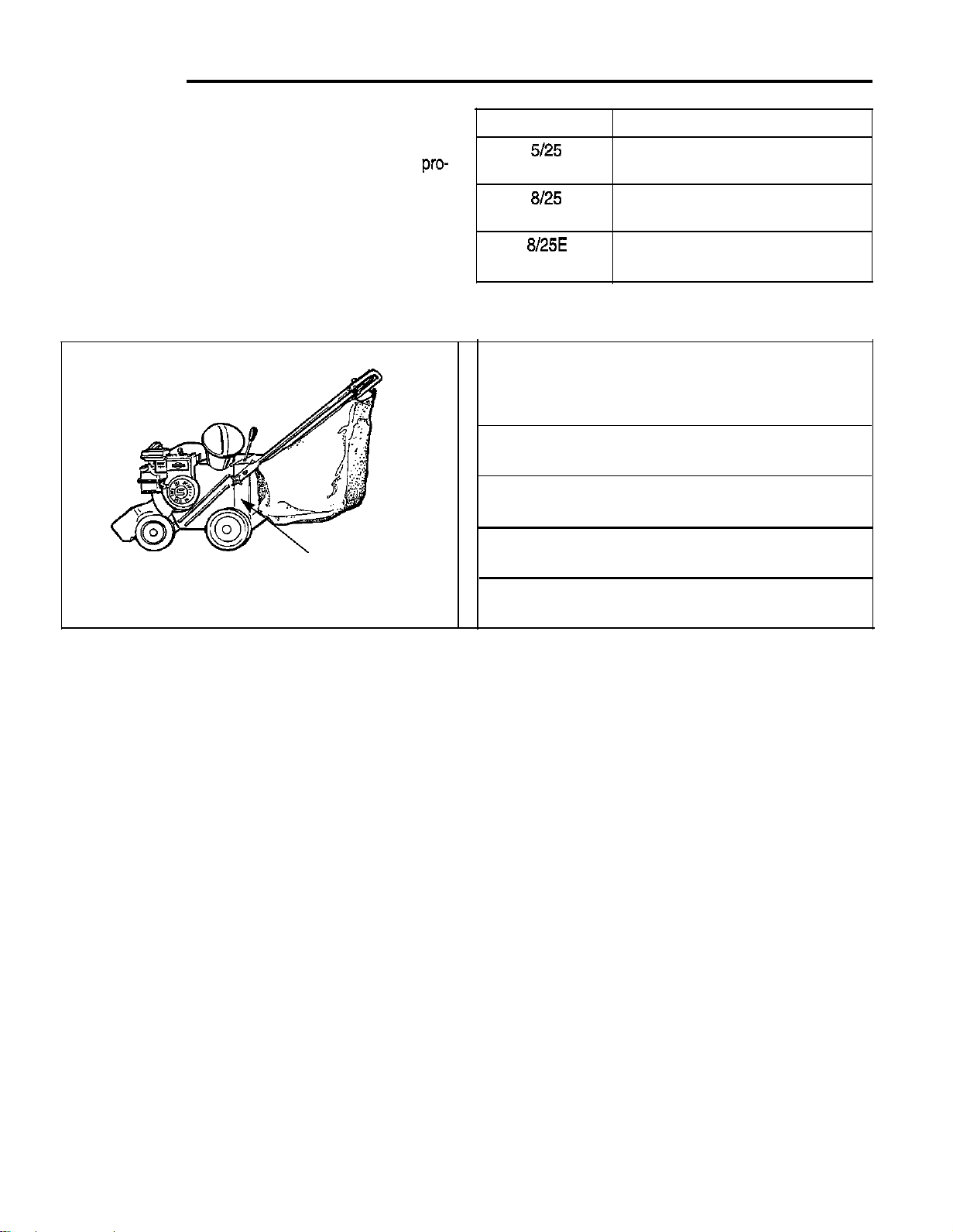
Record your model number, manufacturer number
and serial numberfrom the I.D. tag in the space
vided t for easy reference. The Chipper Vacuum I.D.
tag is located on the side of the unit as shown in the
illustration below.
l
Refer to the engine manufacturer’s owner’s manual
for the location of the engine serial number.
l
Be sure to fill out and return the Warranty
Registration Card supplied with your unit.
Identification Tag
Location
Model
MODEL REFERENCE
Model Number:
Manufacturer Number:
Engine I.D. Number:
Dealer Name
Date Purchased:
Mfg. No.
1692371
1692582
1692372 1692583
1692373
1692584
1692374 1692585
1692466 1692586
1692467 1692587
2
Page 7

DESCRIPTION
General
The shredding chamber is designed to shred materials
that have been vacuumed directly into the unit through
the extra-wide vacuum intake nozzle or through the flexi-
ble vacuum hose, eliminating the need to manually load
or feed material into the shredder.
Selective vacuum-shredding can be performed with the
optional 20 foot long, large-diameter, quick-connect hose
while the unit is stationary, permitting
controlled vacuuming of areas such as flower or shrub
beds, or other confined or landscaped areas.
Large yard, garden, or other open, flat surface areas
can be cleaned up quickly and efficiently using the
Chipper Vacuum’s self-propelled feature, which permits
vacuuming of materials while the unit propels itself.
Shredding Action
Material is drawn into the shredding chamber by the
vacuum action of the spinning rotor, and is pulled into
the path of patented shredding hammers that are rotat-
ing at the same high speed as the rotor. The hammers
cut and grind the material into progressively smaller
pieces, and the flow of air then conveys the fully
ded,reduced waste into the discharge bag.
Vacuum Action
rocks, gravel, and other debris before use. All materials and other debris that could damage the shredding hammers should be removed and properly dis-
posed of before starting the unit.
l Se particularly watchful for small, sharp objects such
as old nails, pieces of glass, and small metal objects
such as cans, can lids, bottle tops, etc.
l Review all operating safety instructions in this manu-
al before proceeding.
l Determine where the discharge bag will be emptied,
and if possible, plan a vacuum path that will allow
you to access this area easily while vacuuming.
Chipper Operation
The chipper is designed to handle tree limbs and
branches up to
up to 3” diameter on
process tough organic matter such as corn stalks and
berry canes.
Chipping operations should be performed while the unit
is stationary, and positioned so that the operator has
firm footing and easy access to the chipper cone area.
Tree limbs and branches should be inserted “butt end”
first into the chipper cone, and are fed into the chipper
block. The sharp cutting edges and angle of the blades
actually pull the tree limbs and branches into the chipper
block, cutting the material into small chips.
HP models. The unit can also
In addition to the shredding hammers and chipping
knives, the rotor has fan blades integrated into its
design. When the rotor is spinning, a constant, powerful
vacuum action is created, which aggressively pulls
waste into the shredder chamber for shredding.
These spinning fan blades also create a blowing force
that ejects the shredded or chipped material out of the
discharge chute and into the discharge bag, making
room for more material to be pulled in and processed.
Vacuum/Shredding
l Vacuum/Shredding can be performed in confined
areas using the vacuum hose attachment, or on
large, flat areas using the
extra-wide vacuum intake nozzle.
l Areas containing rocks, gravel, or other hard materi-
als should be avoided, as these types of materials
will damage the shredding hammers or reduce their
service life. Use of the unit to vacuum non-organic
materials will void the product warranty.
l Areas to be vacuumed should be inspected for
power drive and
The chips of material then pass through a slot in the
rotor behind the chipper knives, where air flow conveys
them through the fan chamber and into the discharge
bag.
Blower Operation
The vacuum force makes it possible to use the unit as a
large-area, self-driven blower for clean-up of grass clip-
pings or other debris that you may not want to collect for
disposal or recycling.
Using the Chipper Vacuum in this mode requires the
removal of the discharge bag, and the attachment of the
optional deflector elbow. The deflector elbow is needed
to direct the powerful exhaust stream to either side of
the unit.
When used in this manner, the operator walks behind
the unit, allowing the discharge deflector elbow to blow
the lightweight debris toward an area where it can be
easily gathered later for disposal, or, as in the case of
grass clippings or other organic matter, be allowed to
decompose naturally as an added nutrient for the soil.
3
Page 8
The Safety Alert symbol shown to the left is used to alert you to important safety information that must be
A
read, fully understood, and followed at all times when handling, transporting, operating, servicing, or storing
your Chipper Vacuum.
intensity, or level, of the hazard the safety alert instructions pertain to. The following list of signal words is being
provided to help you understand the hazard levels associated with each signal word used in this manual.
Each safety alert symbol is followed by a “signal word” that advises you of the relative
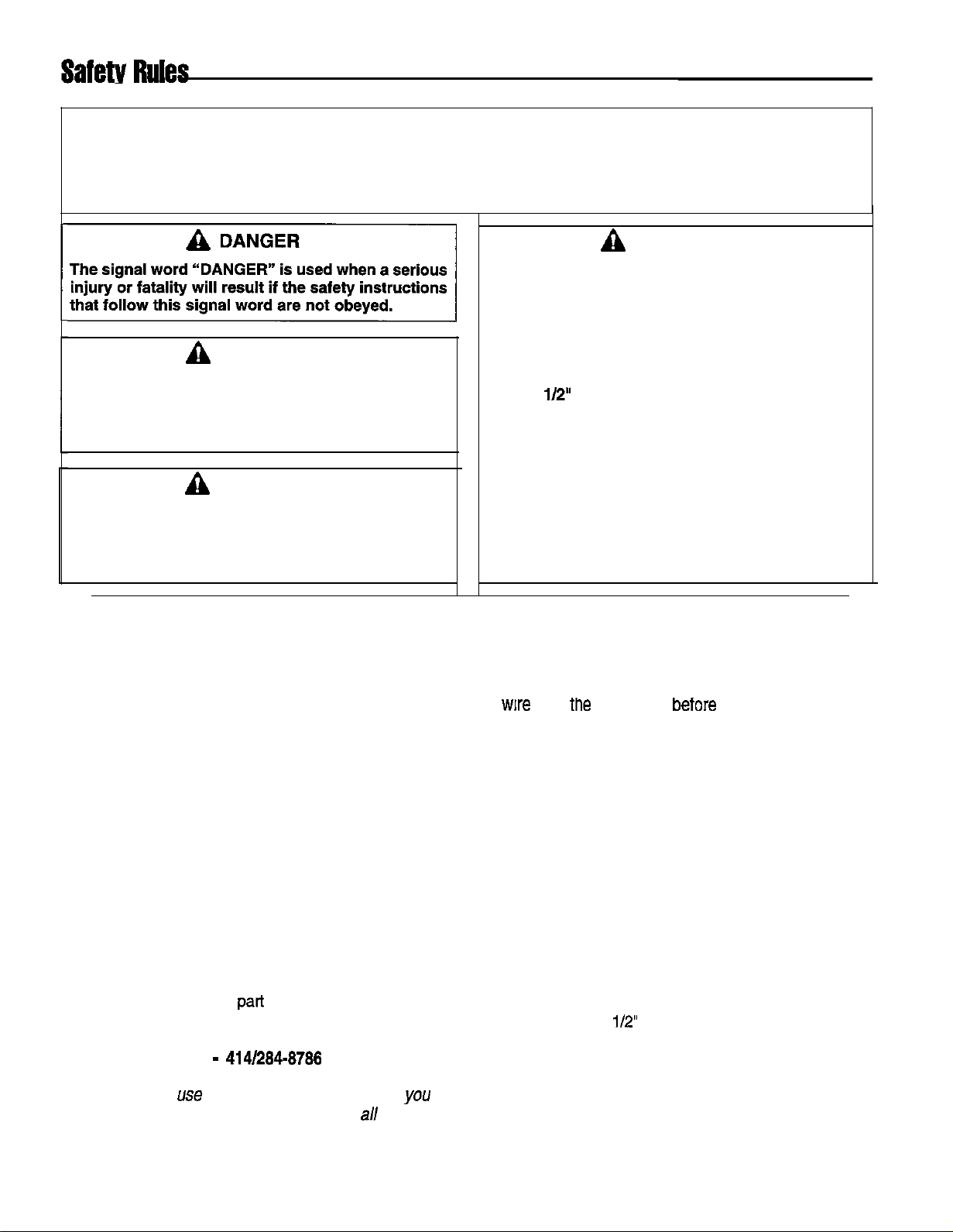
DANGER
The signal word “DANGER” is used when a serious
injury or fatality will result if the safety instructions
that follow this signal word are not obeyed.
WARNING
The signal word “WARNING” is used when a serious injury or fatality could result if the safety
instructions that follow this signal word are not
obeyed.
CAUTION
The signal word “CAUTION” is used when personal injury, or property or equipment damage could
result if the safety instructions that follow this signal word are not obeyed.
You must read and understand this manual and all
safety instructions and labeling completely, before
attempting to assemble, set-up, transport, operate,
service, or install any options or accessories on
this unit.
This Chipper Vacuum is a powerful machine
designed for chipping of tree limbs and branches
up to 2
capable of amputating or causing serious injury to
fingers, hands, feet, and other extremities if acci-
dental contact with rotating chipper or shredder
blades should occur.
Always keep hands, feet, and other extremities out
of the chipper cone and vacuum intake areas, and
never wear loose fitting clothing or jewelry that
could get caught on tree limbs or branches, and
pull your hands, or other body parts into the rotat-
ing chipper blades.
GENERAL
Safe operation of the Chipper Vacuum requires that all
operating and safety instructions be obeyed by everyone
who uses, services, or otherwise handles the unit.
Although the instructions and warnings appearing in
this manual cover most normal operating conditions,
everyone using the Chipper Vacuum must also always
follow safe work practices while operating, servicing, or
handling the Chipper Vacuum unit under any conditions
not specifically covered in this manual.
The primary operator of the Chipper Vacuum must
always be alert for the presence of bystanders, who are
likely to be unaware of the operating and safety requirements necessary for safe operation. It is the operator’s
responsibility to prevent bystanders from being exposed
to potential hazards whenever the Chipper Vacuum is
being used.
If you do not understand any portion of these safety
instructions, or any other
manual, contact your local factory-authorized dealer for
help, or request factory assistance by calling: Customer
Service Department
NOTE: DO NOT use the Chipper Vacuum unless
are sure that you know how to comply with
and operating instructions.
of the instructions in this
414/284-3786
safety
BEFORE START-UP
l Inspect the chipper cone for any debris, or other
material that may have fallen in during unpacking
and assembly. Always disconnect the spark plug
attempting to remove
any objects from the chipper cone.
l Never fill the fuel tank indoors! Gasoline vapors are
explosive, and can easily travel unnoticed to sources
of ignition, such as pilot lights or open flames on
water heaters, furnaces, stoves, dryers or sparks
from electric motors and other electrical appliances,
or smoking materials. Contact with these or any
other ignition sources will cause an explosion or fire,
serious personal injury, and damage to property and
equipment.
l Gas cap shall never be removed or fuel added with
the engine running.
l Never overfill the fuel tank. Fuel may run out of the
tank and contact hot engine surfaces and ignite,
causing a fire and/or risk of an explosion. Always fill
the fuel tank to
l Use only an approved container for fuel, and always
handle the container with extreme care. Never
smoke while fueling or transporting the fuel container.
4
Page 9

l Never store the fuel container or Chipper Vacuum
indoors where there is a possibility of contact with
any ignition source such as a spark, open flame,
pilot light, heating element, or smoking materials.
l Never attempt to test or operate the unit indoors or in
an enclosed area. Engine exhaust contains carbon
monoxide, an odorless, colorless, and tasteless gas.
If inhaled, carbon monoxide can cause dizziness or
nausea, and if prolonged contact occurs, uncon-
sciousness, brain damage, or death can result.
l Check all parts to ensure that they are properly
attached and that all hardware is secure.
l Make sure the discharge bag is securely attached to
the discharge chute and is properly supported by the
bag supports on the bottom of the handle, and the
sides of the rear frame.
l Make sure you have read and understand the engine
manual accompanying the Chipper Vacuum, and
know the location and function of all operating con-
trols for your model Chipper Vacuum. You must
understand how to start and stop the unit safely
before proceeding.
OPERATING LOCATION
l Always operate the Chipper Vacuum outdoors only,
on a firm, level, earthen or grassy area where the
unit will be stable and will stay in position. Never
attempt to operate the unit on a slope greater than
20 degrees, or on wet or slippery surfaces where
you or someone else could slip and fall toward the
chipper cone opening.
l Never operate the unit on rocky, gravel, or
covered surfaces, as this material could be sucked in
to the shredder housing through the vacuum intake
openings and cause damage to the shredder.
l This equipment shall not be operated in the vicinity
of bystanders. Never operate the unit where children,
pets, or others who may be unaware of the potential
hazards associated with chipping, shredding, or vacuuming operations could enter the area unexpectedly
and be exposed to these hazards.
l Never use the optional hose kit to vacuum up rocky,
gravel, or stone-covered surfaces,, as this material
will cause damage to the shredderand other internal
components.
l Never operate in an area where sparks from the
muffler could ignite surrounding dry brush or other
flammable materials. See following Fire Hazard
Warning!
l Wear hearing protection when the Chipper Vacuum
is to be used for prolonged periods of time, or when-
ever noise reaches an uncomfortable level.
CAUTION
SPARK/FIRE HAZARD
GAS ENGINES MAY REQUIRE A SPARK
ARRESTER FOR SAFE OPERATION
If the engine on this unit is not equipped with a
spark arrester and is to be used on any forest,
brush, or grass-covered unimproved land, a spark
arrester must be added to the muffler before using
the engine on such land. The arrester must be
maintained in effective working order by the opera-
tor. In the State of California, the above is required
by law (Section 4442 of the California Public
Resources Code.) Other states may have similar
laws. Federal laws apply on federal lands. See your
authorized engine service center for muffler spark
arrester options.
SAFE WEARING APPAREL
l Always wear safety goggles to protect your eyes
from flying debris when operating the Chipper
Vacuum. One pair of safety goggles has been provided with the unit for your immediate use. All oth-
ers in and around the immediate area must also
wear approved safety glasses to protect their eyes
from flying debris.
l Always wear properly-fitted leather work gloves to
protect your hands from cuts and scratches caused
by tree limbs and branches. Never wear gloves with
pull-ties or straps, as these straps could get entan-
gled with branches and draw your hands into the
chipper cone cutting areas.
l Never wear loose-fitting clothing, hanging jewelry,
ties, scarves, or other items that could get caught on
tree limbs or branches, and draw body parts into the
cutting areas of the chipper cone.
l Always tie up long hair and prevent it from hanging
down, where it could become tangled in branches or
get caught in rotating parts and pull you into the cut-
ting areas.
l Even if you are wearing heavy-duty leather work
gloves, never, ever place your hands in the chipper
cone while the unit is running. If you must reach in
to clear a jam or free up branches, shut the unit off,
allow the rotor to come to a complete stop, discon-
nect the spark plug wire at the spark plug, and care-
fully remove or clear the jammed material.
OPERATING SAFETY
l Always obey the size limitations for tree limbs and
branches stated in the Waste Materials Guide sec-
tion of this manual.
5
Page 10

Safety Rules
l Never leave the machine running unattended.
Always turn off the engine, wait
to a complete stop, and disconnect the spark plug
before leaving the area. Always move the unit to a
safe storage area for prolonged idle periods.
l Never allow children to operate the machine. Do not
allow adults to operate it without proper instruction.
l Always maintain secure footing and solid balance
while starting or operating the Chipper Vacuum.
Never lean directly over the machine.
l Select a speed suitable for operating conditions, and
stay clear‘of hazards such as large bushes, trees,
fences and anything else that could become caught
on or entangled with any part of the unit. Sudden
contact with these obstacles could cause a momentary loss of control of the unit, or cause you to lose
your balance and fall.
l Although the engine is powerful, never attach any
kind of cart or riding attachment to your Chipper
Vacuum. This is a walk-behind unit only, which will
provide years of reliable service when used properly.
l Always stand to one side of the chipper cone when
feeding tree limbs and branches. They may
sionally whip around forcefully or “kickback” while
being chipped.
l Always keep hands out of the chipper cone when
feeding materials. Never wrap fingers tightly around
branches as you are feeding them into the unit, as a
sudden inward surge could
into the unit.
* If you are not using the discharge bag to collect
chipped debris, always direct the debris flow away
from yourself and others, and always stay clear of
the discharge area to avoid being struck by ricochets
or material being ejected from the machine.
l Never force material as it is being fed into the
machine, as this may result in a sudden kickback of
the material with sufficient force to injure you or other
bystanders.
l Never allow material to build up around the engine
during Chipper Vacuum operation. This could result
in a fire, or overheating of the engine.
l When using the Chipper Vacuum as a walk-behind,
large-area blower, always make sure the area to be
cleared of debris is free of gravel, stones, and other
hard debris that could be propelled with great force
by the powerful blowing action possible with this unit.
l Never continue to operate the machine if it starts
making unusual noise or vibration. Shut the engine
off immediately, allow the rotor to stop, disconnect
the spark plug wire from the spark plug, and do the
a. Inspect the unit for any signs of damage or for-
eign material in the chipping or shredding areas.
Remove any solid material that may be prevent-
ing the unit from operating properly.
b. Check for loose parts, and loose or missing hard-
ware, and repair or replace as reauired.
c. Check the oil level in the engine crankcase. See
the engine manual for the specific location of the
oil dipstick, the correct
the
of oil to add if the oil
is low.
Never attempt to clear clogs from the chipper cone
or discharge area while the unit is running. Always
shut the engine off, allow the motor to come to a
complete stop, and remove the spark plug wire from
the spark plug before removing excess materials,
Never fill the fuel tank while the machine is running
or while the engine is hot. An unexpected spillover
of fuel could contact a hot surface and ignite, caus-
ing fire or explosion. Turn off the engine, and allow
the engine to cool before attempting refilling.
l Never attempt to perform any maintenance, repairs,
or attachment of accessories while the unit is
ning. Always shut the unit off, allow the engine to
come to a complete stop, and remove the spark plug
wire from the spark plug before beginning these.
activities. See engine manufacturer’s owner’s
al for anv exceptions.
l Never remove covers, deflectors, or warning labels
.
from the unit. If any of these are found to be miss-
ing, take the unit out of service until the appropriate
repairs can be made. Tag the machine so others do
not mistakenly attempt to use it while awaiting parts
or repairs.
l Always make sure that the chipper cone area is
empty before restarting the unit after it has been idle.
Attempting to start the unit with material in this area
could cause the engine starting cord to jerk or stop
suddenly, causing a risk of injury to your hand or
arm.
l Never tamper with any engine controls to alter or
increase maximum unit running speed. An
speeding condition could cause the engine to over-
heat, resulting in risk of fire, permanent engine dam-
age, and voiding of your product warranty.
l Always comply with the engine manual instructions
for operating and periodic maintenance require-
ments. Make sure the oil level is always in the safe
zone, and keep the air filter element clean.
l Never attempt to defeat, bypass, or disable Chipper
Vacuum safety features. Making alterations to this
6
Page 11
Safety Rules
equipment can result in serious injury, damage to
equipment, and voiding of your warranty.
TRANSPORTING AND STORAGE
l If you must travel across rock, gravel, or other
debris-covered terrain, set the engine speed control
to Wow”, and close the variable suction control flap
by moving the selector lever to the “closed” position.
l Never lift the unit using the fuel tank, vacuum intake
areas, or covers for support. If the unit must be lifted
for vehicular transportation, always use at least two
people, and always grip the unit securely using the
units rigid steel frame. The power drive feature
should only be used for loading by experienced
operators using ramps designed to ensure that the
unit stays properly positioned on the ramps while the
Chipper Vacuum is moving.
l If the unit must remain tilted for transportation, con-
sult the engine manual for required preparation,
Normally, engine fuel and oil must be drained to prevent dangerous fuel leakage, and unwanted transfer
of the sump oil into the cylinder head area.
l Always refill the oil sump with the recommended oil
before attempting to use the unit again after it has
been drained for transportation.
l Always observe safe refueling and fuel handling
practices when refueling the unit after transportation
or storage.
l Always follow the engine manual instructions for
storage preparations before storing the unit for
longed periods.
l Always follow the engine manual instructions for
proper pre-use start-up procedures when returning
the unit to service.
SERVICE AND MAINTENANCE
l Always follow recommended engine and Chipper
Vacuum procedures when performing required service and maintenance on the unit.
l Use only factory-authorized replacement parts for
repair along with recommended factory specifications
on all settings and adjustments.
l Never attempt to make major repairs on this unit
unless you have been properly trained and certified
to work on high-capacity gasoline powered Chipper/
Shredder or Chipper Vacuum units. Improper service procedures can result in hazardous operation,
equipment damage, and voiding of the product war-
ranty.
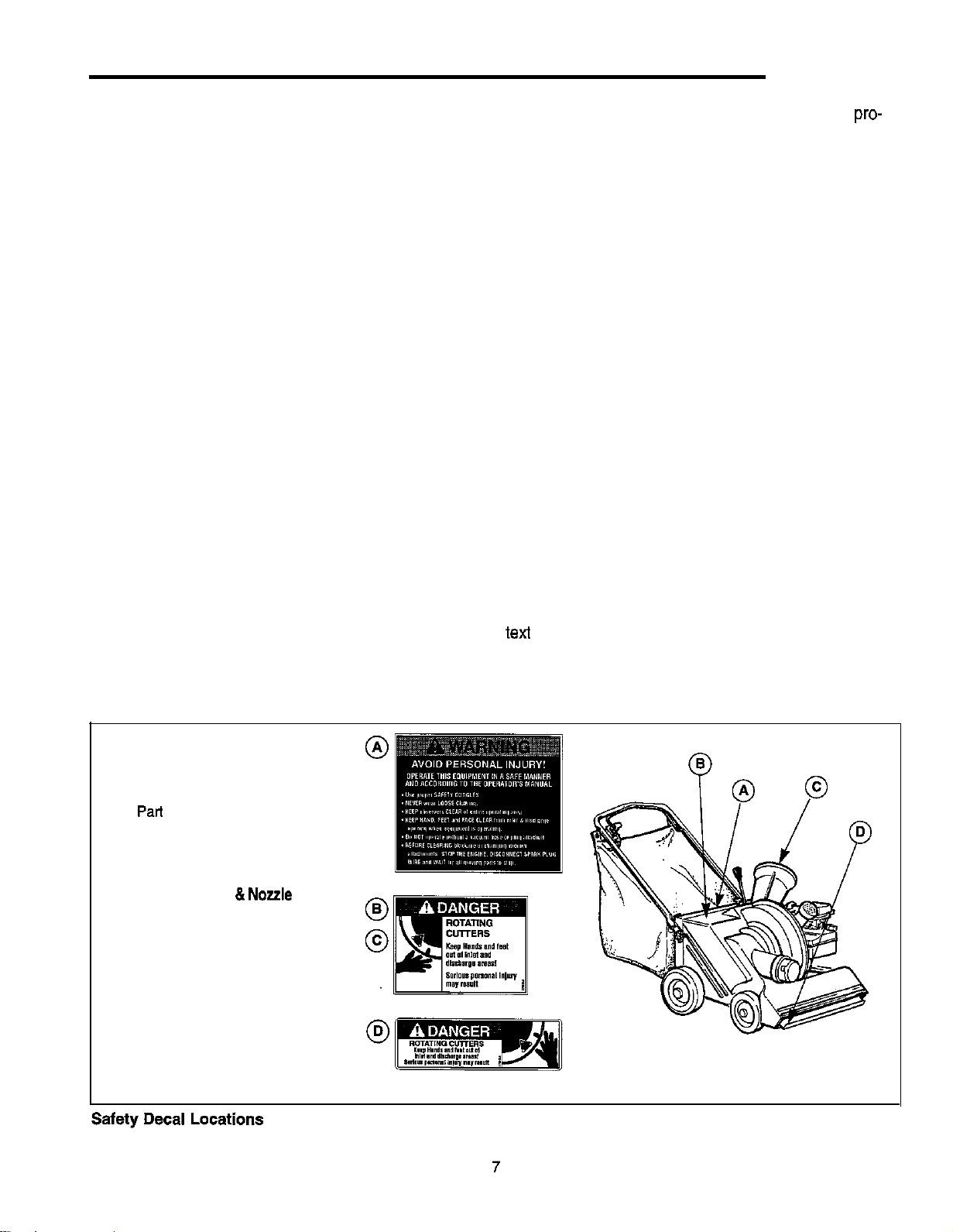
SAFETY DECALS
Important safety labels are shown in the following illustration. Please review these labels and if you have any
questions regarding their meaning or how to comply with
the instructions, re-read the complete safety instruction
or factory Customer Service Department. Use the pan
number information provided to order a replacement
label from your local factory-authorized dealer.
A. Operator Instruction Label
Part No. 1713665
B. Discharge Chute Danger Label
C. Chipper Cone Danger Label
Pad No. 5001612
D.
Vacuum Hose
Danger Label
Nozzle Intake
Part No. 1709529
Page 12
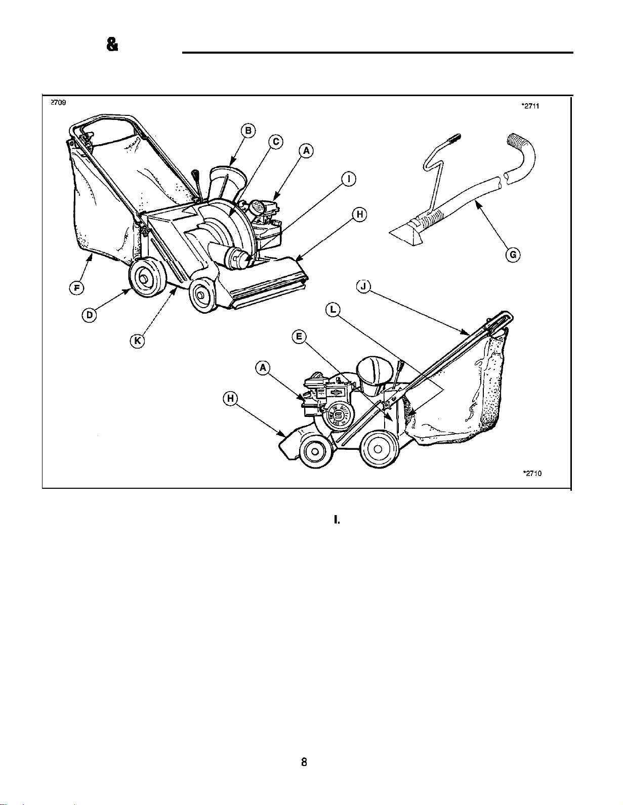
Features & Controls
MAJOR COMPONENTS
OPTIONAL HOSE KIT ASSEMBLY
Engine
. Chipper Cone/Chipper Knives
. Shredding Chamber
. Drive Wheels
E. Frame
F. Discharge Bag
G. Vacuum Hose w/Nozzle (optional)
H.
Vacuum Nozzle w/Variable Suction Control
Vacuum Hose Intake
J. Handle Assembly
K. Transmission (not shown)
L. Discharge Tube.
Page 13

CONTROLS
A. Choke
The choke controls the fuel to air ratio, and helps make
cold starts easier by providing a rich, easily-ignited fuel
mixture.
B. Throttle
The throttle controls engine speed, and allows you to
conserve fuel by powering down during idle periods, or
to achieve optimal chipping/shredding/vacuuming power
by running the engine at full speed.
C. Vacuum Nozzle Variable Suction
The vacuum nozzle Variable Suction Controlru is direct-
ly above and behind the vacuum nozzle, and has four
quick-set opening settings for variable nozzle suction
control:
l closed (for vacuuming with the optional hose
attachment)
l
open,
213 open
l full open.
Smaller nozzle openings provide the necessary vacuum
force for smaller debris, while a larger opening provides
the suction necessary for larger debris like large leaves.
D. Vacuum Nozzle Height Control
The vacuum nozzle height control lever is located at the
rear frame in front of the discharge bag. Three height
settings are available: Low, Medium, and High.
The low setting is suitable for smooth, hard surfaces,
while the medium and high settings are used for different terrain conditions. Settings are easily changed by
simply positioning the control lever into one of three different slots.
The height adjustment control may be fine-tuned by
means of an rod adjustment that permits precise position control for vacuuming of smooth surfaces. See the
adjustment procedure in the TROUBLESHOOTING
REPAIR section.
Operating Controls Locations (5 HP model shown)
E. Drive Speed Control
The Chipper Vacuum is self-propelled, and features
three forward speeds to help match vacuuming action to
surface conditions The drive speed control lever is
mounted on the handle within easy reach of the operator, permitting quick changes in travel speed. This feature allows you to rapidly adjust to changing conditions.
F. Power Drive Bail Lever
The power drive bail lever operates the clutch, the
mechanism that transfers power from the drive shaft to
the transmission.
Pulling the bail lever down against the Chipper Vacuum
handle engages the transmission, which drives the unit
forward for vacuum/shredding or moving the unit around
your yard and garden.
Releasing the lever disengages the transmission, stopping the power drive motion, and allowing the unit to
come to a stop to make adjustments, empty the bag, or
perform chipping or hose vacuuming operations.
Page 14

Operation
SITE LOCATION
1. Select an area that will provide stable footing for
both the Chipper Vacuum and the operator. Do not
operate on wet, slippery surfaces, or in areas with
heavy pedestrian traffic that may distract you from
alert operation of the unit.
2. Locate the Chipper Vacuum near the waste materials
to be chipped to reduce unnecessary lifting and
carrying.
3. Trim and stack the materials to be chipped for more
efficient and safe operation of the Chipper Vacuum.
4. Provide sufficient room for maneuvering around the
Chipper Vacuum. Never set up the work area so that
operators must over-reach or have to step over
materials to be processed.
5. Review all operating safety instructions before
proceeding.
6. Determine whether you wish to
bag to collect the chipped material, or the discharge
deflector elbow to direct the chipper discharge to a
safe area.
7. The optional discharge deflector elbow should only
be used when the unit is positioned over a sofi
surface such as soft dirt or grass, and should always
be directed to the side and away from the operator.
8. If the discharge bag is to be used, be sure to allow
adequate access around the Chipper Vacuum for
bag removal and reattachment.
DANGER
Internal combustion engines produce Carbon
Monoxide, a colorless, odorless, and tasteless gas
that can cause dizziness, nausea, unconsciousness, and even brain damage or death if breathed.
Operate the Chipper Vacuum outdoors in a well
ventilated location only.
Keep children, pets, and bystanders away from the
operating and discharge areas.
Failure to follow these instructions may result in
serious injury or death to you or bystanders.
the discharge
2. Inspect the chipper cone and make sure that it is
firmly attached to the shredder housing.
3. Check all parts to ensure that they are properly
attached and that all fasteners are properly tightened.
4. If a discharge bag is not going to be used to accu-
mulate waste material, make sure the discharge
deflector elbow is directed away from the operator,
and that the area selected for accumulation of
chipped or shredded material will not cause ejected
material to be deflected toward the operator or
bystanders.
5. If a discharge bag is being used, make sure it is
attached to the discharge chute securely, and is
correctly supported by using all four support straps.
6. Open the Variable Suction
intake flap on
the nozzle, and check to make sure no unwanted
debris or other objects are stuck in the nozzle.
7. Fill the fuel tank to a level no closer than
from
the bottom of the filler neck. Obey all safety precautions while handling and fueling the unit. Use regular,
unleaded gas only.
8. Check oil level if unit has not been operated since
initial set-up.
9. Before attempting to start the unit, make sure:
l fuel cap is attached securely,
l oil dipstick is fully inserted in dipstick port,
l chipper cone cap is installed over chipper cone
opening if chipping is not to be performed,
l speed control lever is in normal, disengaged posi-
tion, and speed control selector is in position
um hose intake opening plug must be fully inserted
into intake opening.
To use
l hose end must be fully inserted in hose intake
flexible hose for vacuuming:
opening.
l
Variable Suction
setting is set to closed
position.
l
area to be vacuumed is clear of rocks, gravel,
other hard or sharp debris, and small animals and
pets.
CHECKS BEFORE STARTING
Inspect the chipper cone for debris and other objects
that may have fallen into the machine while the unit
was idle, and remove them before starting the unit.
Before reaching into the chipper cone, always
disconnect the spark plug wire first to prevent
accidental starting of the unit.
START-UP
The controls required to start the Chipper Vacuum are
located on the engine, and are marked “Choke” and
“Throttle” (Figure 1). A more detailed description of
engine operation and all related precautions and proce-
dures can be found in the engine manufacturer’s manual
supplied with each Chipper Vacuum.
Page 15

Operation
Starting The Engine
1. Move choke lever to full choke position.
2. Move throttle lever to “fast”.
3. Place foot on front wheel to hold unit firmly in place,
and adopt a stable stance.
4. Pull starting rope out slowly one time and allow to
return normally.
5. Pull starting rope out with a steady pull, and allow
rope to return normally.
6. When engine starts, gradually move choke lever to
“no choke” position.
7. Maintain throttle speed at ‘fast” for best performance.
Starting The Engine
Move choke lever to full choke position.
2. Move throttle lever to “fast”.
3. Turn key to
4. Release key when engine starts, allowing key to
return to “on’ position.
5. When engine starts, gradually move choke lever to
“no choke” position.
6. Maintain throttle speed at ‘fast” for best performance.
Manual Start Units
Electric Start Units
position
Choke
throttle
controls
Figure 1. Typical Choke And Throttle Controls
Bail Lever
Idle Speed
Use the “idle” position on the throttle lever to reduce
stress on the engine when chipping or
ding is not being performed. Lowering the engine speed
to “idle” will help extend engine life, as well as conserve
fuel and reduce the noise level of the equipment.
WALK BEHIND VACUUM/SHREDDING
Normal operator position for power-drive, walk-behind
vacuum/shredding is directly behind the unit holding the
units handle securely with two hands. This position provides the best combination of unit control, forward and
side
and overall operator safety (Figure 2).
Figure 2. Pull Bail Lever Down And Grip Against
Handle To Engage Transmission
The powered wheel drive is engaged by pulling the
width bail lever down where it can be comfortably
gripped against the chipper vacuum handle. Releasing
the bail stops the forward movement and disengages
the transmission, making it easier to turn or maneuver
the unit.
11
Page 16

Operation
Drive Speed Selector
Forward speed is selected using the speed control lever
mounted on the right side of the handle. The speed
control lever has three positions: slow, medium or fast
(Figure 3).
The ability to select different speeds for differing types of
waste material pick-up and varying surface conditions
helps give you precise control over the unit, which is fur-
ther enhanced by the 3-position vacuum height adjust-
ment and
(These adjustment features will be covered later.)
SLOW SPEED - POSITION #l
Slow drive speed is selected when the lever is pulled all
the way back toward the operator into position number
one (Figure 3).
Slow speed is recommended for initial use to help the
operator get accustomed to the driving characteristics of
the unit, and to move the unit very short distances, or for
using the flexible vacuum hose.
Slow speed is also recommended for vacuum/shredding
of wet leaves on heavy density ground cover such as
long, wet grass or thick weeds, or wherever heavier
materials or rougher ground covering requires concen-
trated vacuuming action.
MEDIUM SPEED
Medium drive speed is selected by moving the lever to
position
Medium speed is used when vacuuming leaves that may
be moist, or clinging to medium length ground cover.
FAST SPEED - POSITION #3
Fast drive speed is selected by moving the speed selec-
tor lever to position
Fast speed is recommended for vacuum/shredding of
light, dry leaves or debris on short or light density
ground cover. It may also be used by experienced oper-
ators to move the Chipper Vacuum long distances.
(Figure 3).
(Figure 3).
CAUTION
Changing drive speed should only be done while
the unit is stopped and the bail lever,+ completely
released. Attempting to change drive speed while
the unit is running may damage the transmission or
cause premature wear of transmission and clutch
components.
Figure 3. Speed Selector Lever And Positions
CHIPPING
General
Variations in the size and hardness of the materials
being chipped will affect how quickly the material is
pulled in to the chipping knives. Small diameter
softwood branches will
diameter hardwood tree limbs, so be prepared for
different feeding speeds when changing the type of
material you are chipping. Kiln-dried dimensional
lumber may be too hard to chip properly.
Speed Selector Lever
WARNING
Release the bail lever immediately to stop the for-
ward travel of the unit if you see, step on, or sus-
pect to encounter any dangerous debris such as
rocks, gravel, glass, or other hard or sharp objects
anywhere in the path of the Chipper Vacuum.
Clear the debris before proceeding, and dispose of
the material properly to prevent contact with it
again later.
Allowing the Chipper Vacuum to vacuum these
types of materials may result in personal injury to
the operator or bystanders, and will damage the
shredding hammers, reducing shredding efficien-
cy, and voiding the warranty.
l Always maintain a stable, well-balanced stance to
one side of the unit when operating the chipper
(Figure 4).
l Never stand directly in front of the chipper cone
when performing chipping operations, since occasional kick-backs or twirling of branches and limbs
may occur, resulting in
limb or branches.
being struck by the tree
12
Page 17

l Hold tree limbs and branches carefully as they are
being put into the chipper cone, releasing your grip
as soon as the self-feeding action of the chipper
knives begin to pull the material in.
l Longer pieces may have a tendency to twirl around
forcefully as they are being drawn into the chipping
knives. Hold the material safely away from the chipper cone area until the material is properly controlled
by the chipper cone.
l Never wrap your fingers around tree limbs and
branches, or hold so tightly that you can’t let go
quickly if the tree limb or branch is suddenly and
forcefully pulled into the chipper block chipping
knives. Short pieces may be pushed into the chipper
using longer limbs and branches. Stand to the side
when feeding shod pieces, since they may kick back.
Operation
Figure 4. Proper Operator Stance For Chipping
Feeding Material
1. Prune tree limbs and large branches to limit size to
the maximum diameter allowed. Pruning tree limbs
and branches close to the main portion of the limb or
branch will make feeding into the chipper cone
er, and will help you maintain control as the material
is drawn into the chipper block.
2. Large, hard or dried-out tree limbs that tend to resist
chipping can be processed by rotating them manually as you alternately insert and retract them in the
chipper cone.
3. If the material to be chipped is extremely hard and
kicks back forcefully, or cannot be easily controlled
while it is being fed into the unit, remove the material
immediately and set it aside. You may need to sharpen
the chipper blades to process the material. Consult
the repair section of this manual for sharpening instructions, or take your unit to an authorized service center.
4. If normal chipping operation begins to require additional feeding force to process material, the chipper
knives may be in need of routine sharpening. See the
repair section of this manual for sharpening instruc-
tions, or take your unit to an authorized service center.
5. Always try to maintain adequate control of the tree
limbs and branches being fed into the chipper cone
to prevent them from whipping around and causing
injury to you or damage to the cone. Larger limbs
and branches may have a tendency to kick back
toward the operator, so always be alert as you feed
materials into the cone. Always, feed the large end of
the limb in first.
6. Avoid chipping limbs or branches that you suspect
may have imbedded objects such as hooks, eyelets,
nails, screws, or other metal items that could dam-
age the chipping knives. If possible dispose of them
using another means.
7. Check the chipper cone periodically to make sure it
is securely fastened to the housing.
cone become loosened, stop the unit, and tighten
assembly hardware securely.
FLEX HOSE VACUUM/SHREDDING
Vacuum/shredding of confined areas such as plant beds
and decorative landscaping can be performed quickly
and effectively using the 15’ flexible vacuum hose available for your Chipper Vacuum.
Changing over to flex hose vacuuming can be done
quickly and requires no tools.
To convert your unit for use with the
hose, just follow these easy steps:
1. Shut the unit off if it is running, and allow the rotor to
come to a complete stop. (Make sure any material
being shredded or chipped is completely processed
before stopping the unit.) When the rotor is fully
stopped, no noise or vibration will be noticeable.
2. Set the vacuum intake nozzle flap adjustment to the
closed position.
3. Remove the vacuum hose intake plug from the
vacuum hose opening, and store it where it won’t get
damaged or lost (Figure 5). Placing the plug into the
chipper cone opening will keep it readily available
when you want to resume walk-behind vacuuming.
NOTE: When removing the vacuum hose intake plug or
hose connector end, align the seam on the cap or hose
connector with the seam on the
then pull out to snap it out of the intake opening groove,
and unscrew to remove.
If the chipper
flexible vacuum
13
Page 18

Operation
4. lnserl the connector end of the vacuum hose into the
intake opening, using care to fully seat the connector
in the opening. If the connector is not fully inserted,
and electrical interlock switch will keep the unit from
starting or running (Figure 6).
5. Place the hand-held vacuum intake nozzle in the
area to be vacuumed, using care to avoid twisting
and minimize bends in the hose.
6. Visually inspect the area to be vacuumed to make
sure it is clear of small pets, non-shreddable materials, and any other hazards that could damage the
shredding hammers if vacuumed into the unit.
7. Perform the Checks Before Start-Up described earlier in this manual.
8. Stan the unit in accordance with standard starting
instructions for the type of unit you have.
9. For maximum vacuum force, set the throttle control
on the engine to the maximum speed setting.
gradually open the vacuum adjustment port
(Figure 7).
11. Using the vacuum intake nozzle, vacuum the area
you wish to clear, using care to avoid vacuuming
rocks, gravel, and other hard or sharp objects that
are not shreddable.
Use extra care near landscape borders that may be
separating grassy areas from landscape rock or
stone.
13. Se watchful for small children, pets or other animals
that may enter the area.
Figure 5. Remove Vacuum Hose Intake Cap
Insert Hose
Figure 6. Insert Vacuum Hose Connector Into Hose
Intake Opening
Vacuum Force
WARNING
The chipper vacuum is equipped with an electrical
safety interlock switch which prevents the unit from
operating when the vacuum intake cap or hose is
removed from the inlet opening. See your dealer if
the safety interlock switch is not operating properly.
DANGER
Never reach into the shredding chamber area of an
electric start unit unless the start key has been
removed and the spark plug wire has been disconnected.
Always wear work gloves to protect your hands
from sharp edges and objects that may have been
vacuumed into the unit.
Figure 7. Vacuum Force Adjustment
SHUTTING DOWN
When you’re done using the Chipper Vacuum, following
these simple but worthwhile steps will help you shut
down the unit properly so ihat your next use will be
trouble-free.
DANGER
The engine and surrounding parts become
extremely hot during normal use, and will cause
serious burn injuries if touched before the engine
has cooled. Allow the engine to cool completely
before touching these hot surfaces.
1. When you have completed processing the materials
to be chipped or vacuum/shredded, shut the unit off
and allow the rotor to come to a complete stop
before proceeding
14
Page 19

2. Remove the spark plug wire from the spark plug to
prevent the possibility of inadvertent starting. On
electric-start models, remove the key to prevent anyone from inadvertently activating the electric start
feature. Although the unit won’t start with the spark
plug removed, the rotor will turn, and serious injury
could result if your hands are in the area of the rotor
or chipper knives.
3. Inspect the following areas for any remaining materials that may have built up or become caught during
operations:
l vacuum intake nozzle
l vacuum hose intake opening
l chipper cone
l discharge chute
l engine air intake area
l transmission/clutch area
NOTE: Do not spray water on the transmission to clean
it, A/though it is sealed to protect it during normal use,
doing so may force water into the transmission housing,
causing corrosion or transmission failure. Use a small
brush or air stream to clear debris away from this area.
Operation
Figure 8. Unhook Support Straps
Figure 9. Loosen Cinch Strap
MATERIAL COLLECTION & DISPOSAL
Direct Bagging
Chipped material may be collected using the discharge
collection bag. Check the bag frequently to make sure it
is filled to a level you can comfortably handle when
removing and emptying the bag.
1. To remove the bag, shut the unit off, and let the
rotor come to a complete stop. Unhook the rear and
front support straps, (Figure
strap that holds the bag opening to the discharge
chute. (Figure 9)
2. Pull the bag off and away from the discharge tube
(Figure
securely at the front and rear to balance the weight
as you lift it.
3. Place the bag down in the disposal area, and unzip
the zipper opening completely. Lift the bag by the
other end and the contents of
out easily.
4. Zip the bag closed, and reinstall in the reverse
sequence followed for bag removal. Tighten cinch
strap securely (Figure 11).
NOTE: The discharge bag may be emptied without
removing the bag from the Chipper Vacuum by simply
unzipping it and raking the material out by hand. This
method is ideal for heavier debris that may make lifting
and carrying the bag difficult.
Figure IO. Pull Discharge Bag Off Discharge Tube
Figure 11. Tighten Cinch Strap Securely
Direct Discharge
Chipped material may be discharged directly into a
selected collection area by installing the discharge
deflector elbow on the discharge chute. When direct
charge is being used, the deflector elbow must always
be directed away from the operator.
15
Page 20

Operation
A safe collection area should be located where children,
pets, and bystanders will not come into contact with
chipped material as it is being discharged, or be hit by
deflected pieces that may ricochet away from the collection area with great force.
When using direct discharge, check the discharge area
frequently for accumulation of material near the discharge port, and make sure the material can be safely
ejected away from the unit. Letting material accumulate
directly in front of the units discharge port may cause a
jam.
Direct Discharge Blowing
The direct discharge method of clearing debris can also
be used to clear driveways or other large areas. Make
sure the discharge deflector elbow is directed to one
side of the unit, then blow debris away from the center
of the area toward the outer edges.
Do not discharge against a fence or wall where
charged material may deflect back toward you and possibly cause injury. If a wall, fence, or other obstacle is
encountered while clearing an area, stop the unit,
change the direction of the discharge stream, and blow
debris away from the obstruction.
FIGURE 9. Variable Suction Control Adjustment
A. Closed Flap Opening
B. Narrow Flap Opening
C. Medium Flap Opening
D. Wide Flap Opening
WARNING
Never attempt to move the unit while material is in
chipper cone being chipped.
Always allow limbs and branches to be completely
processed before engaging the power drive bail
lever.
Failure to obey these instructions may result in
jamming of the chipper, or erratic power drive performance causing sudden starting and stopping of
the power drive.
Figure 10. Vacuum Intake Nozzle Height Adjustment
A. High Height Adjustment
B. Medium Height Adjustment
C. Low Height Adjustment
Height
used with flexible hose
light debris
small leaves
large leaves
Adjustment Lever
Selecting the right combination of vacuum nozzle
height and flap opening position may require a little
experimenting to find the settings that work the best for
off and allow the rotor to come to a complete stop.
Never start the unit without securely attaching the
discharge bag or installing the discharge elbow in
a safe direction. Failure to obey these instructions
may result in serious injury.
OPERATOR AU
OPERATOR ADJUSTMENTS
Three different suction control settings and three nozzle
Three different suction
height positions provide a total of nine
height positions provide a total of nine different positions
for handling virtually any type of lawn
for handling virtually any type of lawn surface and yard
waste conditions.
you.
Variable Suction Control Adjustment
The variable suction control adjustment is located just
above and to the rear of the vacuum intake nozzle. This
adjustment sets the size of the intake opening, allowing
you to match the vacuum suction force to the type of
The vacuum intake nozzle flap has four easily-set
tions: closed (for vacuuming using the flexible 20
hose), small, medium, and large. These positions are
set and maintained by the vacuum nozzle flap adjust-
ment bracket, using a simple pull-and-place lever that
16
grouna cover Deing vacuumed.
Page 21

Operation
slides smoothly into place in one of four slots (Figure 9).
To adjust the opening of the vacuum intake nozzle flap:
1. Grip the curved portion of the lever arm,
2. Pull the lever out of the present slot,
3. Slide the lever into the desired slot.
Vacuum Intake Nozzle Height Position
The vacuum intake nozzle height adjustment is located
at the rear of the frame on the left side of the unit
(Figure 10). This adjustment controls the height of the
vacuum intake nozzle above the ground.
SEASONAL HINTS
l Keep the lawn cut short during leaf clean-up season.
Although your Chipper Vacuum is designed to handle
tough clean-up jobs, you will save time and effort
when the ground cover gets moist or matted if your
lawn is mowed short.
l Vacuum frequently if your lawn is subject to a heavy
deposit of leaves. Attempting to vacuum extremely
thick deposits of leaves may require frequent stop-
ping and starting to allow the unit to fully process the
material in the shredding chamber.
l On extremely damp ground cover, leaves sometimes
get vacuumed into the unit in lame clumos. Go slow
avoid clogging the vacuum intake housing, and let
the shredder fully process material before vacuuming
additional debris.
l Frozen ground cover will require raking before
uming can be performed. Break up frozen clumps of
leaves or other debris before attempting to vacuum
the material.
l Extremely wet ground surfaces may impede wheel
traction and make maintaining secure operator foot-
ing difficult. Allow surfaces to dry out before
uming if it is hard to maintain positive control of the
l Operation on wet surfaces may result in a rapid
build-up of debris on wheels and on the underside of
the unit. Be sure to remove any build-up before
putting the Chipper Vacuum away. Moist debris will
be easier to remove than material that has been
allowed to cake on the unit and dry.
* A light coating of WD-40 on drive chains will help
prevent corrosion between uses if the unit has been
subjected to extremely wet operating conditions.
17
Page 22

WASTE MATERIALS GUIDE
Your Chipper Vacuum is designed to efficiently process
a wide variety of organic yard and garden waste
als. To obtain consistent performance, extend the life of
your unit, and help ensure safe operation, do not
attempt to process non-organic materials, and always
follow the material requirements shown in the Waste
Materials Guide below.
If you are unsure about processing a material not covered in the guide below, contact your local authorized
dealer, or call our
If you encounter any difficulties while processing any of
these recommended materials, consult the
ing sections of this manual for guidance and
mended corrective action,
Customer Service Department at
for assistance before proceeding.
Power
Drive
Vacuum/
Shredding
Chipping
Dry, moist, or wet organic
material, including leaves, clippings,
seeds, pine needles, cones,
and other organic lawn
debris that is shreddable
Vacuum at drive speed
and nozzle settings that
consistently provide
thorough material pick-up
Tree limbs, large branches,
or small branches grouped
together for ease of handling.
Never use the chipper
to chip very hard, dry materials
such as kiln-dried dimensional
lumber
building and lumber yard materials.
Never use the Chipper Vacuum to
chip pressure-treated wood products
such as landscape timbers, fence
posts, or other outdoor building or
landscaping lumber products.
Branches and twigs
to l/4” diameter
and 4” long.
Fruit and vegetable
waste that will pass
through vacuum intake
nozzle
3” Diameter limbs,
branches, or small
groups of branches.
Avoid long pieces
(over
outer end can twirl
in a circular motion
and strike you or
bystanders, causing
personal injuries.
Maximum Diameter:
Model
Model
as the
(2-i/2”)
(3”)
Rake very wet materials
to separate them from
ground cover that may
impede normal vacuuming
operations.
If time permits, allow wet
material to dry out for a few
days prior to vacuum/
shredding.
Bulky tree limbs and
branches should be
pruned close to the main
stem to pass through the
chipper cone properly.
As the material is chipped,
short
lengths may be
pushed into the chipper
with another tree limb or
batch of branches.
Never attempt to chip
material suspected of
containing nails, hooks, o
other metal objects.
Vacuum
Hose
Operation
Loose, dry waste such as
leaves, grass clippings, seeds,
pine needles, cones, and other
organic lawn and yard debris.
Avoid vacuum operation on areas
where hard, non-organic materials
such as gravel, dirt clumps, or
other hard objects could get
vacuumed into the shredder chamber.
Smaller materials that
will not obstruct the
hose as its
being vacuumed.
18
The
hose is designed
for small, loose waste and
for cleaning around decorative
landscaping and
flower beds.
Page 23

Normal Care
. I
SCHEDULED MAINTENANCE
Your Chipper Vacuum has been designed to provide you with years of reliable operation. Keeping your Chipper
Vacuum in top running condition will prolong its life, and help you obtain optimum performance whenever you wish to
chip or shred yard or garden waste.
operating intervals to extend the life of your unit.
Please read this normal care schedule, and observe these recommended care
ITEM
Check For Loose Pans
Check Oil Level And Add As Req’d
Change Oil
Change Spark Plug
Clean Engine Air Intake Area
Clean/Oil Air Filter Element
Inspect/Rotate Shredding Hammers
Inspect/Sharpen Chipping Knives
Inspect/Adjust Drive Chains
Inspect Drive Belt
Inspect Starter Rope/Handle
Inspect Chipper Cone
Hardware
Page Each Use 5 Hrs 25 Hrs
19
.
20
I
I I l I
20
I I
20
33
32
I
20
20
l
I
l
l
.
I
l
.
l
Inspect Vacuum Nozzle
Lubricate Wheels, Pulleys,
Check All Safety Labels
Battery Maintenance (Electric Start Only)
Optional Vacuum Hose
* See engine manufacturer’s owner’s manual supplied with the unit.
SERVICING THE CHlPPEq VACUUM
Housing
Sprockets
21
20
20
21
21
Read the engine manufacturer’s owner’s manual for any
engine maintenance required.
General
The following information will help you make the
necessary checks and perform the procedures required
to follow the normal care recommendations made for
your Chipper Vacuum unit,
If you prefer, your local authorized dealer can make these
checks and perform the required procedures for you.
Loose Parts And Hardware
Check the following areas, and tighten as required:
l Chipper cone and cone mounting
l Vacuum intake housing mounting
l Discharge deflector mounting
l Top and side covers
19
.
.
.
l
Page 24

Clean Engine Air Intake Area
The engine is air-cooled, and requires unobstructed air
flow into and around the engine. The cooling fins on the
engine cylinder head area must also be kept clear of
chipper and shredding deposits, as well as any other
build-up of debris that could prevent heat from radiating
away from the engine (Figure 14).
To clean the air intake area, remove any external material build-up, and then blow out the area using a stream of
compressed air. If a compressor is not available, use a
stiff-bristle parts brush, which is available at most auto
parts supply stores.
To clean the cooling fins, brush the area between the
fins with a stiff bristle parts brush, and blow out any
remaining debris with a stream of compressed air. If the
cooling fins are caked with an oily build-up of debris,
using a commercially available engine cleaner aerosol
may help loosen and remove the deposits. If you use
such a product, you must follow all safety and use
instructions to prevent damage to the engine components and personal injury to you.
Using a stream of water to clean the engine requires
immediate drying of engine components to prevent
rusting and possible malfunctioning of the electrical
system. If a water stream is used to clean debris, start
the engine immediately, and allow engine heat to speed
drying.
Inspect Starter Rope/Handle
The recoil starter rope and handle should be inspected for
signs of abrasion or wear that could result in breakage.
Contact your local authorized dealer for replacement if
these parts need to be replaced.
Figure 14. Engine Air Intake Area
Inspect Chipper Cone
Check the cone to make sure that it hasn’t been damaged or worn excessively by constant use, and replace
it if it is cracked, worn out, or no longer fits securely on
the chipper cone mounting flange.
Cracks, worn areas, and loose attachment points can
cause material to jam or clog when feeding it into the
machine, and may result in kick-back or other hazard to
the operator.
Contact your local dealer for replacement parts if your
unit shows any evidence of these problems, and discon-
tinue use of the unit until the appropriate repairs can be
made.
Check Safety Labels
Inspect/Rotate/Replace Shredding
Hammers
Consult the Troubleshooting and Repair Section of this
manual for complete disassembly, inspection, and
replacement instructions.
Your local authorized dealer can provide this service to
you if you do not wish to disassemble the unit and
inspect/repair it yourself.
The safety labels located in various positions on the
Chipper Vacuum have been placed to help remind you
of important safety rules while you are operating or
transporting the Chipper Vacuum unit.
If any label can’t be read or is missing, contact your
local dealer for an immediate replacement. If you must
use the unit without the label, review the label informa-
tion in the “Safety Decals” section of this manual.
Clean
Around
Area
Inspect/Sharpen Chipping Knives
Consult the Troubleshooting and Repair Section of this
manual for complete disassembly, inspection, and
replacement instructions.
Your local authorized dealer can provide this service to
you if you do not wish to disassemble the unit and
inspect/repair it yourself.
Lubricate Wheels, Pulleys, and Sprockets
To lubricate, squirt 3-5 drops of SAE 30 oil on each
wheel axle at the wheel bearings, and at each bearing
on the pulleys and sprockets. Wipe up any run-off and
spin wheels briefly to work oil around entire axle
Inspect Vacuum Nozzle Housing
Check the vacuum nozzle housing for build-up of debris,
20
Page 25

Normal Care
and clean out if required. Always shut engine off and
remove the spark plug wire from the spark plug before
reaching into the housing to clear material.
For stubborn debris, the vacuum nozzle housing can be
removed from the unit following the steps in the hammer
service section of this manual, and hosed out with a garden hose.
fluid levels to run down below full may result in erratic
starting performance, or inability of the battery to provide
adequate power to operate the starter motor.
To check battery fluid:
Inspect Vacuum Hose (Optional)
Repetitive use may result in a build-up of debris on the
inner walls of the flexible vacuum hose. If this occurs,
remove the hose from the unit, and rinse out with a
den hose. Allow the hose to dry before reusing. Inspect
the hose for any sticks or small branches that may have
become lodged inside, and remove.
Checking/Cleaning Battery Cables
BAG CARE
The discharge bag is designed to allow air to pass freely
through the material, while safely retaining discharged
material from the chipper and shredding chamber. -Use
of the Chipper Vacuum in extremely dusty or dry conditions may cause a build-up of fine debris on the bag fab-
ric, reducing the air flow and the efficiency of the vacu-
um action. If this occurs, remove the bag from the unit
and turn it inside out, and brush or vacuum it clean. If
you have purchased the hose kit accessory, you can use
the hose kit to vacuum the bag clean.
BATTERY MAINTENANCE
(Electric Start Units Only)
Checking Battery Fluid Level
Check the battery fluid periodically to make sure that the
fluid level is maintained at the “full” mark. Allowing the
WARNING
When removing or installing battery cables, disconnect the negative cable FIRST, and reconnect it
LAST. If not done in this order, the positive terminal can be shorted to the frame by a tool, creating
a dangerous spark that can ignite fuel vapors or
escaping hydrogen from the battery.
1. Remove the top cover.
2. Remove battery filler cap. Battery fluid must be even
with split ring “full” mark. If necessary, add distilled
water to bring fluid level up to full level.
3. Reinstall battery filler cao
1. Disconnect the cables from the battery, negative
cable first.
2. Clean the
wire brush and battery post terminal cleaner.
3. Reconnect cables, positive cable first.
4. Coat cables and clamps with grease, petroleum jelly,
or a protective aerosol spray coating designed to
provide a protective barrier on electrical connections.
terminals and cable clamos with a
WARNING
Lead-Acid batteries contain sulphuric acid, a high-
ly corrosive liquid that can cause severe chemical
burns if allowed to come into contact with skin, or
blindness if allowed to contact your eyes. Always
wear eye goggles and protective gloves when handling or servicing the battery.
Lead-acid batteries also produce hydrogen, a colorless, highly explosive gas that can be easily ignited by a single spark. Always disconnect the negative cable first and reconnect it last to prevent a
spark from occurring if a tool accidentally contacts
the positive terminal and any part of the machine
frame at the same time.
Never smoke or allow ignition sources to be near-
by while servicing the battery.
Never attempt to charge a discharged battery without first checking the fluid level and making sure
the fluid is to the full level.
21
Page 26

Storage
TEMPORARY STORAGE
(30 Days Or Less)
Here’s a quick checklist of things to do when storing
your Chipper Vacuum temporarily, or between uses:
l Keep the unit in an area away from where children
may come into contact with it.
l When this equipment is stopped for service, inspec-
tion, or storage, or to change an accessory, operators shall make sure the spark plug wire is discon-
nected from the spark plug.
l Remember, the Chipper Vacuum fuel tank probably
will still contain some gasoline, so never store the
Chipper Vacuum indoors or in any other area where
fuel vapor could travel to any ignition source. Fuel
vapor is also toxic if inhaled, so never store the
Chipper Vacuum in any structure used for human or
animal habitation.
l Never put the unit away while the engine is still hot
from running. Let the engine cool down first to
prevent the chance of fire.
l Never try to lift or position the unit in the storage
area by holding the fuel tank. Always let the engine
and muffler cool completely before allowing yourself
to contact these parts.
l If the unit can’t be stored on a reasonably level
surface, use a block of wood to chock the wheels.
Never store the Chipper Vacuum where it will not be
in a stable position.
l Never tip the unit more than 45” from vertical, and
never lay the unit on its side, as this could cause fuel
leakage, and/or undesirable oil transfer into the
cylinder head and spark plug area. Excessive oil in
the cylinder head will prevent the engine from starting
properly.
l Cover the Chipper Vacuum unit to protect it from
debris and foreign objects.
l Avoid damp storage locations to prevent rusting of
metal parts.
l When this equipment is stopped for service, inspec-
tion, or storage, or to change an accessory, operators shall make sure the spark plug wire is discon-
nected from the spark plug.
l Drain fuel system completely following engine
manufacturer’s instructions or add fuel stabilizer to
prevent fuel from gumming up during extended
storage period.
l Clean external surfaces, engine and cooling fan.
l Remove spark plug, and squirt 1 ounce of SAE 30 oil
into spark plug hole.
l Plug hole and pull starter cord slowly or crank engine
briefly to distribute oil evenly in cylinder head area.
l Reinstall spark plug.
l Transport unit to a suitable storage location. If you
have chosen to use a fuel stabilizer and have not
drained the fuel system, follow all safety instructions
and storage precautions in this manual to prevent
the possibility of fire from the ignition of gasoline
fumes. Remember, gasoline fumes can travel to
distant sources of ignition and ignite, causing risk of
explosion and fire.
l For additional convenience and a reduction in the
amount of floor space required for storage, the
handle assembly may be moved to a vertical position
by removing the locking knobs and carriage bolts,
loosening the bag support cap screws, and rotating
the handle up toward the unit. Be sure to keep the
locking knobs and carriage bolts with the unit for
reinstallation when the unit is put back into service.
LONG TERM/SEASONAL STORAGE
(Longer Than 30 Days)
Your Chipper Vacuum can be safely stored during
seasons by following these simple storage instructions:
l For extended storage periods, run the unit dry of
gas.
Electric Start Units Only
l Be sure the battery is fiiled to the proper level with
water and is fully,charged. Battery life will be
increased if the battery is removed and put in a cool,
dry place and fully charged about once a month. If
the battery is lefi in your unit, disconnect the
Cable to prevent battery drain during storage.
22
Page 27

Troubleshooting & Repair
GENERAL TROUBLESHOOTING
The troubleshooting guide below lists the most common
problems, causes and remedies.
See the service information on the following pages for
instructions on how to do most of these minor repairs
yourself. If you prefer, all of these procedures can be
performed for you by your local authorized dealer.
Engine won’t start.
l Out of gas.
l Spark plug wire disconnected.
l Engine controls set wrong.
l Spark plug fouled.
l No compression
without resistance.
l No spark
problem.
l Safety switch open.
WARNING
Never attempt to perform any of these procedures
with the engine/motor running. Always turn the
unit off, let the rotor come to a complete stop, and
disconnect
Failure to comply with this safety requirement can
result in serious personal injury to you or
bystanders.
rope pulls
electrical system
spark plug wire or power cord
to correct any operatmg
l Add gas.
l Connect spark plug wire.
l Check engine controls and
adjust.
Remove spark plug, clean, and
replace.
l See your local dealer.
l See your local dealer.
l Check safety switch.
Engine runs, but rotor
won’t turn.
Engine runs, rotor turns, but
no material is being discharged.
Excessive branch vibration when
chipping materials.
Unusual noise or vibration when
processing material.
Vacuum intake nozzle
not working.
l Crankshaft key broken or not
installed.
l Discharge chute clogged.
l Engine not running at full RPM.
l Chipper knives dull.
l Tree limbs and branches are
extremely hard or dried out.
l Rotor overloaded with material.
l Non-organic matter caught in
shredding chamber.
l Chipper knives dull or loose.
l Hammers, broken, bent, or loose
l Hammers frozen on shaft.
l Crankshaft bent.
l Housing plugged with debris.
l Nozzle set too high for terrain.
l Flap not set to correct opening.
l Drive speed set too fast.
l Debris too wet.
l Debris layer too thick.
l Replace crankshaft key.
l
Clear discharge chute.
l
Adjust throttle to “Fast” (3700rplr
l Sharpen or replace knives.
l Material too dried out or hard
for chipping
l Allow unit to clear itself before
use for firewood.
vacuuming more material.
l Follow shut-down procedure and
remove material from unit.
l Sharpen or tighten knives
Securely.
l Check for proper assembly or
replace.
l Check for obstructions and
remove debris from
hammer pivot areas.
l See your local dealer for
factory authorized repair.
l Stop unit
l Adjust
l Adjust
l Reduce speed.
l Allow to dry
l Reduce path width to112 nozzle.
clean out housing.
see adjust. procedure.
see adjust. procedure.
rake to separate.
23
Page 28

Troubleshooting & Repair
POWER DRIVE TROUBLESHOOTING
Power Drive won’t engage.
Power drive runs erratically.
Drive chains chatter.
Unusual noise or vibration while
unit is moving.
ELECTRIC START TROUBLESHOOTING
l Bail lever cable too loose.
l Bail lever cable end not
engaged in clutch lever.
l Drive belt broken or loose.
l Drive chain(s) broken.
l Drive chain(s) off sprocket.
l Crankshaft key broken or miss-
ing from unit.
Clutch lever obstructed.
l Drive belt worn.
l Drive chains loose.
l Rotor overloaded with material.
l Non-organic matter caught in
shredding chamber.
l Move clip up to next link.
l Insert cable end in clutch lever.
l Repair or replace.
l Repair or replace.
l Reinstall chain(s) on sprocket.
l Replace key.
l Clear obstruction.
l Replace drive belt.
l Adjust sprocket position.
l Allow unit to clear itself before
feeding more material.
l Follow shut-down procedure and
remove material from unit.
Electric start won’t
operate.
OPTIONAL VACUUM HOSE TROUBLESHOOTING
Vacuum hose not working.
l Battery dead.
l Circuit breaker tripped.
l Battery terminals dirty.
l Loose wires/battery cables.
l Ignition switch inoperative.
l Solenoid inoperative.
l Safety switch inoperative.
l Starter motor inoperative.
Vacuum intake nozzle flap open,
l Material too wet.
l Hose not attached securely.
l Hose obstructed or damaged.
l Engine not running at
full RPM.
l Hose nozzle vacuum
adjustment ring opened too far.
l Charge Battery.
l Allow 1 minute for auto. reset.
l Clean terminals.
l Check wiring and tighten
as required.
l Repair or replace switch.
l Repair or replace solenoid.
l Repair or replace switch.
l Repair or replace starter motor.
l Close vacuum intake nozzle flap.
l Allow material to dry.
l Attach hose securely.
l Inspect hose
l Set control to full fast position
repair or replace.
See dealer if problem persists.
l Close adjustment ring.
24
Page 29

Troubleshooting %I Repair
Figure 15. Remove Cover Panel Fasteners
Figure 17. Remove Right Cover Panel Fasteners
SHREDDING HAMMERS
1. Turn the unit off, allow the rotor to stop completely,
and disconnect the spark plug wire.
2. Remove top cover by prying up panel fasteners with
a flat blade screwdriver. Pry panel fastener heads
up to permit gripping with fingers, then pull fastener
heads to remove fastener (Figure 15).
Figure 16. Lift Top Cover Up And Away From Unit
Figure 16. Remove Right Cover
3. Lift top cover up and away from unit (Figure 16).
3. Remove (2) panel fasteners and (2)
ted, hex head screws from right side panel (Figure
and remove panel from unit (Figure 16).
Pull on spring loaded idler to lessen belt tension and
4.
remove belt from pulley. Using a
remove the (2) 5/l 6-I 6
and (2)
ley bearing plate to the frame (Figure 19).
lock washers that secure the drive pul-
hex head cap screws
socket wrench,
slot-
Figure 19. Remove Drive Pulley Bearing Plate
Screws
25
Page 30

Troubleshooting
Repair
Figure 20. Pull Drive Pulley Bearing Plate And Slide
Drive Belt Off Pulley
Figure 22. Remove Vacuum Nozzle Housing Nuts
5. Pull the drive pulley bearing plate straight out, and lift
the drive belt off the pulley to permit complete
removal of the plate assembly (Figure 20). It may be
necessary to tap the plate with a hammer to help
free it from the splined hub assembly on the rotor.
6. Continue pulling the drive pulley bearing plate
straight out, and remove it from the vacuum nozzle
housing. Note that the shaft end is splined to mate
with the splined hub assembly on the
21).
7. Using a i/2” socket wrench, remove the (4)
hex nuts that secure the vacuum nozzle housing to
the shredder housing (Figure 22).
8. Remove the safety interlock leads from the spade
terminal (Figure
24). A l/2” socket and i/2” box wrench are required
to remove the hex nut and hex head screw.
and engine block base (Figure
(Figure
Figure 21. Pull Drive Pulley Bearing Plate Assembly
Out Of Vacuum Nozzle Housing
Figure 23. Pull Off Safety Interlock Wire At
Spade Terminal
Figure 24. Remove Hex Nut And Screw Securing
Safety Interlock Wire #2 To Engine Block Base
26
Page 31

Troubleshooting
Repair
Figure 25. Disassemble Variable Suction Adjustment
Control Bracket From Engine
9. Using a i/2” socket wrench and i/2” box wrench,
remove the hex head screw and hex nut that
secures the variable suction adjustment control
bracket to the engine block base (Figure 25).
Lift the vacuum nozzle housing away from the shred-
der housing and tilt it up slightly to clear the right
front wheel as it is removed from the unit (Figure 26).
Removal of the vacuum nozzle housing provides
access to the shredding hammers. Inspect the J
hammers and triangular hammers for wear, and
replace if worn excessively (Figure 27).
12. Using a
the
It may be helpful to use a short piece of 2 x 4 lumber
to block the rotor while removing the capscrew
(Figure 26).
NOTE: The correct assembly sequence of
shown in Figure 29. A// parts must be reinstalled in the
correct order and location to ensure proper rotor bal-
ance, shredding efficiency, and safety, Use care to
catch the parts as the
13. Install the new J hammer with the bent lip facing out
as shown in Figure 26. (J hammers on this unit can-
not be turned over and reused.) Use new assembly
hardware if the old hardware appears worn out or
damaged. Replace the other J hammer in the same
manner.
1
hammer, remove the hammer and reinstall it on a
new pivot hole. If all cutting edges on the front
surface are worn, turn the triangular hammer over
and reinstall it. Tighten all capscrews securely when
reassembling, but do not exceed 45 ft.
wrench or hex bit socket, remove
is
Figure 26. Remove Vacuum Nozzle Housing
Figure 27. Inspect Hammers For Wear
Figure 28. Remove And Replace Hammers
Hammer-Wear
I
27
Page 32

Troubleshooting & Repair
Rotor
Spacer
J Hammer (2)
D.
Flat Washer
E.
Lock Washer
G.
H.
Triangular Hammer (2)
I.
Bushing, Flanged
J.
Cap Screw 5/16-18
K.
L.
Figure 29. Proper Hammer Assembly
Lock Washer
Chipper Knife (2)
2”
15. Rotate the rotor to move the next hammer into
position for servicing, and repeat step 14.
16. If chipping knives are to be inspected or serviced, go
to the next section for instructions. If service is to be
performed on shredding hammers only, proceed to
the next step.
17. Reassemble the unit in the reverse sequence used
to disassemble it in the preceding steps.
18. Check all hardware for tightness and correct
assembly before attempting to start the unit. Do not
attempt to start the unit if extra hardware or other
parts are left over after reassembly has been
completed. Identify the correct assembly location for
any remaining parts using the illustrations in the
manual, and install as required.
19. Start the unit and listen for unusual noise or vibra-
tion. Stop the unit immediately if any problems are
apparent, and check the assembly of all parts for
proper positioning before starting the unit again.
CHIPPING KNIVES
Chipping knives should be resharpened or replaced
when tree limbs and branches begin to require extra
force to feed into the chipper block.
To inspect and service the chipping knives, follow these
steps: (If hammer service has just been performed, skip
steps
1. Turn the engine off, allow the rotor to stop
2. Remove the top and right side covers as shown in
3. Remove the discharge bag.
4. Remove the panel fastener and slotted hex head
5. Remove the left cover (Figure 30).
6. Remove the panel fasteners from the rear panel
7. Slide the rear panel down, and tilt the rear of the unit
WARNING
Never use the unit for chipping or
ding unless the discharge bag is attached, or the
deflector elbow has been installed.
Material could be ejected out of the discharge
chute with great force, injuring you or bystanders.
Chipper knife cutting edges are sharp. Wear leather
work gloves to protect your hands from injury
when removing or installing chipper knives.
.
7a. Electric start units only: Disconnect and remove the
NOTE: Always remove the negative terminal cab/e first
and reinstall if last to reduce the risk of sparking and
short-circuiting the battery if metal-to-metal contact is
made between the positive terminal and the unit’s frame.
7b. 8 H.P. units only: Remove top screws securing the
2).
completely, and disconnect the spark plug wire.
the preceding hammer replacement section.
screws from the left cover (Figure 29).
(Figure 31).
up slightly to allow the panel to slide free of the
grooves in the discharge tube (Figure 33).
battery.
fuel tank to the frame, and carefully move fuel tank
forward and rest it on drive belt while chipper knife
service is being performed.
26
Page 33

Troubleshooting & Repair
igure 30. Remove Left Cover Panel Fasteners
Figure 32. Remove Rear Panel Fasteners
8. Loosen the discharge tube hex nuts on the right side
of the discharge tube, providing approximately
clearance between the hex nut and the tube
(Figure 34).
9. Using a l/2” socket wrench and i/2” box wrench,
remove the hex head cap screw and hex nut securing the discharge tube to the top brace (Figure 35).
10. Loosen the discharge tube hex nuts on the left side
of the discharge tube, providing approximately
clearance between the hex nut and the tube
(Figure 36).
12. Slide the discharge tube away from the mounting
studs on the shredder housing, and remove the tube
through the opening in the back of the frame
(Figure 37).
Figure 31. Remove Left Cover
,
Figure 33. Remove Rear Panel
Figure 34. Loosen Discharge Tube Hex Nuts
29
Page 34

Troubleshooting & Repair
Figure 35. Remove Discharge Tube Hex Head Cap
Screw And Hex Nut
13. Rotate the rotor to move the first chipping knife into
position at the rear opening in the shredding cham-
ber. Pulling slowly on the starter rope will make the
rotor rotate.
14. Insert a
piece of wood into the chipping/shredding chamber
under the sharp edge of the chipper knife. This will
support the knife as it is disassembled from the rotor,
and prevent the rotor from turning as the mounting
screws are removed.
15. Using an
two cap screws that secure the chipper knife to the
rotor. It may be helpful to clean out the sockets on
the cap screws with a smaller
of bent wire before attempting to remove the screws
(Figure 38).
16. Carefully remove the chipper knife by pulling the
board slowly out of the chipping/shredding chamber.
Avoid touching the sharp edge of the blade with bare
hands as even a “dull” chipping edge can inflict a
serious cut.
17. Rotate the rotor and remove the other chipper knife
following the same procedure.
18. Sharpen both knives equally or replace both to
ensure proper balancing and correct chipping action.
l Chipping knives may be resharpened until the dis-
tance between the mounting holes and the top
edge of the blade bevel is
l Slow speed water-cooled grinding is suggested to
help maintain blade temper and a long lasting
sharp edge. Rapid grinding and heating of blades
will soften the edges, making repeated sharpening necessary.
thick x 1 l/2” wide x IO
wrench or hex bit socket, unscrew the
12” long
wrench or piece
Figure 36. Loosen Discharge Tube Hex Head Nuts
Left Side
Figure 37. Remove Discharge Tube
Figure 36. Remove Chipper Knives
30
Page 35

Troubleshooting & Repair
Front View
Side View
gure 39. Chipper Knife Minimum Distance
ounting Holes To Bevel Edge
l
Chipper knives require a 30” bevel on the cutting
edge (as shown in figure 39) for efficient chipping
action.
Contact your local dealer or blade sharpening
service if you prefer not to sharpen the blades
yourself.
Clean the chipper knife mounting areas with a flat
scraper before reinstalling the chipper knives to
ensure a flat mounting surface.
20. Using the i/2” thick wood board for support, install
the new chipper knives with the two flat head cap
screws removed earlier, and tighten securely. Make
sure the sharp edge is facing down, and the beveled
edge is facing the rotor plate.
21. Reassemble the unit in the reverse sequence used
to disassemble it in the preceding steps. Replace
any hardware that is worn or damaged.
Figure 40. Lift Off Idler Pulley Spring
Figure 41.
Loop Over Idler Pulley Assembly
to use it to perform chipping.
23. Start the unit, and check for unusual noise or
vibration.
l
Shut the unit off immediately if either situation
occurs, and re-inspect chipping knives to confirm
correct positioning and assembly has been done.
l If assembly is correct, blades may not have been
sharpened evenly, causing an imbalance.
Remove blades and sharpen evenly.
l Recheck unit. If problem persists, contact your
local dealer for assistance.
Figure 42.
31
Wrap Belt Around Transmission Pulley
Page 36

Troubleshooting & Repair
Figure 43. Wrap Drive Belt Around Lower Idler
Pulley And Angled Pulley
DRIVE BELT
The drive belt may be accessed by removing the top,
right, and rear covers as shown in previous sections.
2. Remove the drive pulley bearing plate and slip off the
drive belt as shown in Figures 19
3. Lift the idler pulley spring off the threaded stud, and
release tension on the idler pulley assembly. Note
the path of the belt, then remove it through the back
of the unit (Figure 40).
4. Inspect the belt for excessive wear, and replace if
worn out or cracked. Make a loop with the new belt,
and insert it into the rear of the unit, over the pivoting
idler pulley assembly and toward the horizontal transmission pulley (Figure 41).
5. Wrap the belt around the transmission pulley,
beveled edge in, and engage the lower idler pulley
and bottom of the large angled pulley (Figure 42).
6. While maintaining light tension on the belt with one
hand, wrap the drive belt around the lower idler pul-
ley and angled pulley, and hold in place with the
other hand (Figure 43).
7. Pull the pivoting idler pulley assembly back up into
normal position, wrapping the drive belt around the
upper idler pulley. At this point, the slack loop at the
other end of the belt should be toward the drive belt
pulley plate mounting area (Figure 44).
8. Pull the slack end of the drive belt toward the front of
the unit, and loop it over the drive pulley drive shaft
as you place the drive pulley drive shaft into the
vacuum nozzle housing shaft opening (Figure 45).
21.
Figure 44. Pull Idler Pulley Assembly Back And Wrap
Drive Belt Around Upper Idler Pulley
Figure 45. Loop Slack End Of Drive Belt Over Drive
Shaft And On To Drive Pulley
Figure 46. Install Drive Pulley Plate
32
Page 37

Troubleshooting & Repair,
Figure 47. Reconnect Idler Pulley Tension Spring
9. Lift the drive belt over the edge of the drive pulley
and engage the pulley, beveled edge in, and slide
the drive belt pulley plate and drive shaft into
position. Install the two hex head screws and lock
washers removed earlier, and tighten securely
(Figure 46).
Reach around to the back of the unit, and making
sure the drive belt is fully engaged in all pulleys,
reconnect the tension spring to the threaded stud to
maintain tension on the drive belt (Figure 47).
NOTE: The beveled edge of the drive belt should be
engaged against the transmission pulley and the two
pivoting idler
should be engaged against the larger, angled pu//ey with
the wider groove (Figure 48).
Reassemble covers to unit in reverse sequence of
disassembly.
and the flat side of the drive be/t
DRIVE CHAINS
General
Figure 48. Drive Belt Installed Position On Pulleys
Figure 49. Loosen Hex Nut To Adjust Tension On
Front Chain
The drive chains may be accessed by tilting the back of
the unit up, and supporting it securely to prevent the unit
from falling backward during service. Drive chain
access is from under the unit, and extreme care must be
used when checking, tightening, or replacing drive
chains.
full. Drain the fuel tank carefully, and follow all precautions for handling gasoline when performing this step.
Drive chain tension may be adjusted by moving
adjustable sprocket mounting brackets (front chain) or
the drive axle (rear chain) to achieve desired tightness.
Chains will have
sprockets when properly tensioned.
Do not tip the unit for service if the fuel tank is
l/4” (rear) of flex between
Figure 50. Loosen Hex Nut To Adjust Tension On
Right Axle Mounting Bracket
33
Page 38

Repair
Damaged chains may be replaced by first loosening ten-
sion, then disconnecting master link (front chain only) or
removing complete chain (rear chain only), and installing
new chain on sprockets.
Front Drive Chain
1. Loosen hex nut that locks sprocket in position, and
move sprocket forward or backward until chain flexes
approximately
sprockets. Tighten hex nut securely when proper
tension is reached on chain (Figure 49).
2. To replace chain, loosen hex nut to reduce tension,
and separate chain links at master link. Install new
chain over sprockets, and attach end with new mas-
ter link. Readjust sprocket for proper tension, and
tighten securely.
Rear Drive Chain
1. Rear drive chain tension adjustment requires the
drive axle to be moved forward or backward.
2. Loosen axle mounting hardware at both frame
mounting locations to permit movement of drive axle
(Figures 50
3. Move axle forward or backward to achieve desired
tension, making sure rear sprocket is in line with
drive sprocket.
4. When properly tensioned, rear drive chain should
flex approximately
between sprockets.
5. Tighten adjustable axle mounts when proper tension
is reached on the drive chain, and recheck sprockets for alignment. Readjust axle position if necessary to ensure alignment of sprockets.
51).
VACUUM NOZZLE HEIGHT
ADJUSTMENT
Figure 51. Loosen Hex Nut To Adjust Tension On
Left Axle Mounting Bracket
Figure 52. Disconnect Adjustment Rod
I
When properly adjusted, there should be approximately
of clearance between the bottom of the vacuum
nozzle and a flat ground surface with the Vacuum Height
Adjustment lever in the “Low” position. Adjust as follows:
1. Set the vacuum nozzle height adjustment lever to
“LOW”.
2. See figure 52. Have someone tilt the unit all the way
back until you can see the adjustment
Remove the clip from the height adjustment rod and
pull the rod free of the front axle.
3. Turn the rod counterclockwise to lengthen the rod
(Figure 53). Lengthening the rod will reduce the
clearance between the nozzle and the ground; short-
ening the rod will increase the amount of clearance
between the nozzle and the ground.
clip.
Figure 53. Adjusting Rod Length
34
Page 39

4. See figure 52. Reattach the rod to the front axle with
the clip.
NOTE: Changing the rod length will affect the ground
clearance measurement at all height ranges and may be
used to make fine adjustments to the nozzle height at
any position desired.
CLUTCH CABLE
The clutch cable does not require service.
cable should become detached from the clutch lever, follow these steps:
1. Remove the vacuum nozzle housing as illustrated in
the hammer service section of this manual.
2. The clutch lever is located directly in front of the
transmission.
3. To reattach the clutch cable to the clutch lever, push
the clutch lever back with one hand, and insert the
cable end into the hole in the lever (Figure 54).
4. When properly inserted, the clutch cable end hook
will be seated at the second bend in the hook
(Figure 55).
5. With the unit turned off, check the clutch lever for
proper operation by operating the power drive bail
lever.
cable when the bail lever is fully depressed against
the handle of the unit. If the cable is slack, release
the bail lever and move the spring end down one link
on the chain connector, and recheck for tautness.
Adjust tension until clutch cable is taut when bail
lever is depressed (Figure 56).
6. Reassemble the unit in the reverse sequence used
for disassembly.
Make sure that there is no slack in the clutch
If the clutch
Figure 54. Push Clutch Lever And Reinsert Cable End
Figure 55. Proper Clutch Cable Position On Clutch
Lever
Figure 56.
35
Attachment
L
:h
Page 40

Options & Accessories
VACUUM ATTACHMENT
This easy-to-add accessory allows the Chipper Vacuum
to be equipped with a vacuum hose and other attach-
ments to help simplify pick up of lightweight materials
such as leaves and grass clippings. It can also be
adjusted to vacuum without disturbing landscaping
material such as decorative rock.
Technical Manuals
Literature Available
Operators Manuals
Additional copies of this manual
of our product support commitment, we maintain a sto
printed operators manuals going back many years!)
available, (and as
Fully illustrated pans manuals are also available
these manuals show all of the product’s components in
exploded views
the parts and how they go together), as well as giving
ment part numbers and quantities used. Important as
special torque values are included in these manuals.
For the applicable manuals currently available for
Model:
your model, contact our Customer Publications
Department at 414-284-8519. Have the informa-
tion listed in the box at the right available when
Your Name:
phoning in your request.
Please allow 3 to 4 weeks for delivery
Address:
36
 Loading...