


LOW PROFILE TRAILER FRAME & COVER MFG. NO. 624
HIGH CAPACITY TRAILER FRAME & COVER MFG. NO. 531
ATTACHMENTS
ROVING NOZZLE MFG. NO. 447 VACUUM COLLECTOR ADAPTER MFG. NO. 620 VACUUM COLLECTOR ADAPTER MFG. NO. 621
1970 PRODUCTION YEAR
COLLECTOR
Mfrs. No. 619
LITHO IN U.S.A.
Downloaded Non W.M. PanLislo, Cn Inatual Search MginA NUFACTURING COMPANY, INC.
PACKING
The Vacuum Collector is delivered complete in two cartons. The long carton contains:
2 - Hoses
The short carton contains:
- 1 V.C. Blower Assembly
- 1 Deflector
- 3 Hose Clamps
- 1 Flange Hose
- 1 Pack of Hardware
Should any shortages of the above items occur, advise by stating the packers number listed on the green packing slip, part number and description of items missing.
ASSEMBLY
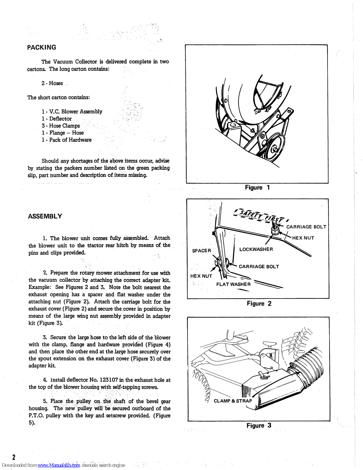
1. The blower unit comes fully assembled. Attach the blower unit to the tractor rear hitch by means of the pins and clips provided.
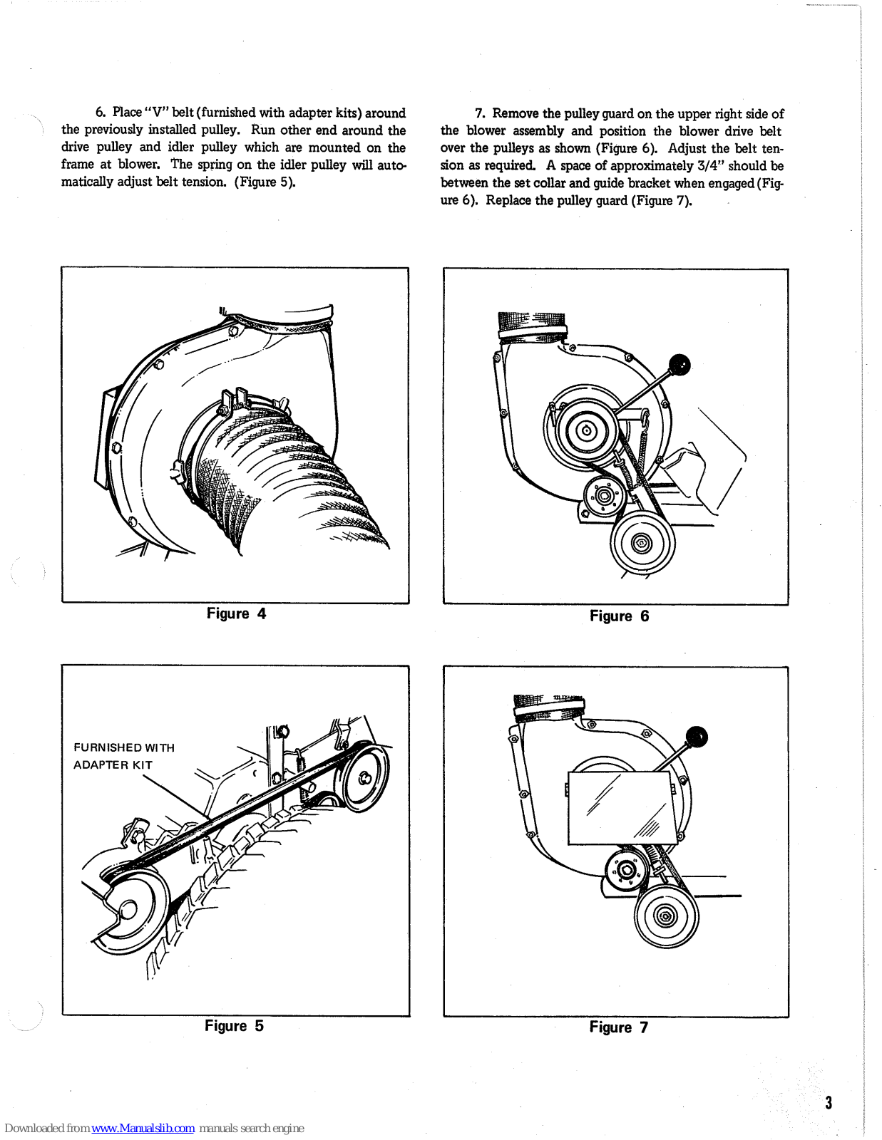
2. Prepare the rotary mower attachment for use with the vacuum collector by attaching the correct adapter kit. Example: See Figures 2 and 3. Note the bolt nearest the exhaust opening has a spacer and flat washer under the attaching nut (Figure 2). Attach the carriage bolt for the exhaust cover (Figure 2) and secure the cover in position by means of the large wing nut assembly provided in adapter kit (Figure 3).
3. Secure the large hose to the left side of the blower with the clamp, flange and hardware provided (Figure 4) and then place the other end at the large hose securely over the spout extension on the exhaust cover (Figure 3) of the adapter kit.
4. Install deflector No. 123107 in the exhaust hole at the top of the blower housing with self-tapping screws.
5. Place the pulley on the shaft of the bevel gear housing. The new pulley will be secured outboard of the P.T.O. pulley with the key and setscrew provided. (Figure 5).
alslib.com manuals search engine


Figure 2

Figure 3
6. Place "V" belt (furnished with adapter kits) around the previously installed pulley. Run other end around the drive pulley and idler pulley which are mounted on the frame at blower. The spring on the idler pulley will automatically adjust belt tension. (Figure 5).
7. Remove the pulley guard on the upper right side of the blower assembly and position the blower drive belt over the pulleys as shown (Figure 6). Adjust the belt tension as required. A space of approximately 3/4" should be between the set collar and guide bracket when engaged (Figure 6). Replace the pulley guard (Figure 7).


Figure 5
Figure 7
3
Mfrs. NO. 531 HIGH CAPACITY TRAILER FRAME & COVER
PACKING
The High Capacity Trailer Frame & Cover Assembly is delivered complete in one carton. The carton contains:
- 1 Canvas Cover
- 1 Door Cover
- 1 Pack of Hardware
Should any shortages of the above items occur, advise by stating the packers number listed on the green packing slip, part number and description of items missing.
ASSEMBLY
The cart enclosure for the vacuum collector consists of a metal framework and a canvas cover, all of which fits on the dump cart body.
1. The canvas cover is completely assembled to the metal framework with the exception of the upper hanger brackets and the front catch.
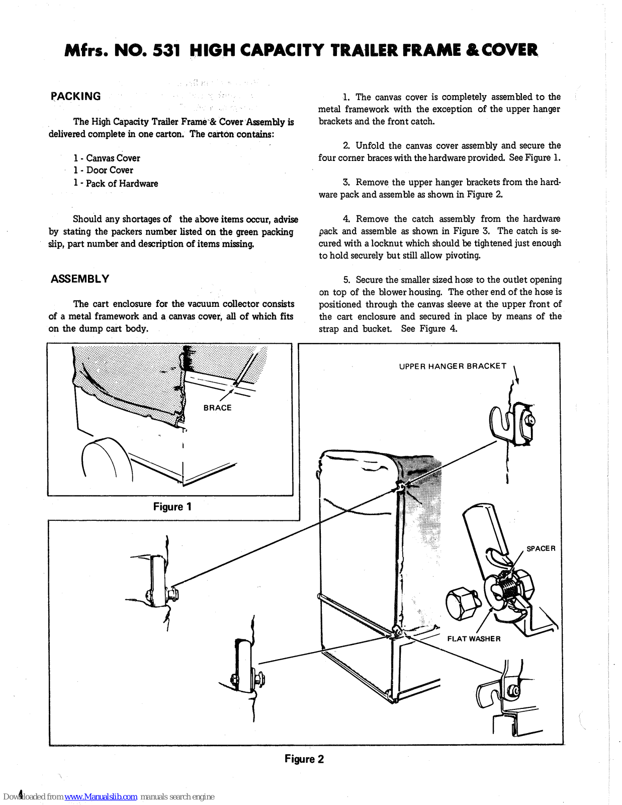
2. Unfold the canvas cover assembly and secure the four corner braces with the hardware provided. See Figure 1.
3. Remove the upper hanger brackets from the hardware pack and assemble as shown in Figure 2.
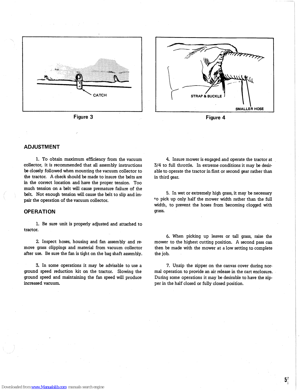
4. Remove the catch assembly from the hardware pack and assemble as shown in Figure 3. The catch is secured with a locknut which should be tightened just enough to hold securely but still allow pivoting.
5. Secure the smaller sized hose to the outlet opening on top of the blower housing. The other end of the hose is positioned through the canvas sleeve at the upper front of the cart enclosure and secured in place by means of the strap and bucket. See Figure 4.

Figure 2

Figure 3

Figure 4
ADJUSTMENT
1. To obtain maximum efficiency from the vacuum collector, it is recommended that all assembly instructions be closely followed when mounting the vacuum collector to the tractor. A check should be made to insure the belts are in the correct location and have the proper tension. Too much tension on a belt will cause premature failure of the belt. Not enough tension will cause the belt to slip and impair the operation of the vacuum collector.
OPERATION
1. Be sure unit is properly adjusted and attached to tractor.
2. Inspect hoses, housing and fan assembly and remove grass clippings and material from vacuum collector after use. Be sure the fan is tight on the bag shaft assembly.
3. In some operations it may be advisable to use a ground speed reduction kit on the tractor. Slowing the ground speed and maintaining the fan speed will produce increased vacuum.
4. Insure mower is engaged and operate the tractor at 3/4 to full throttle. In extreme conditions it may be desirable to operate the tractor in first or second gear rather than in third gear.
5. In wet or extremely high grass, it may be necessary to pick up only half the mower width rather than the full width, to prevent the hoses from becoming clogged with grass.
6. When picking up leaves or tall grass, raise the mower to the highest cutting position. A second pass can then be made with the mower at a low setting to complete the job.
7. Unzip the zipper on the canvas cover during normal operation to provide an air release in the cart enclosure. During some operations it may be desirable to have the zipper in the half closed or fully closed position.
Mfrs. NO. 624 LOW PROFILE TRAILER FRAME & COVER
PACKING
The Low Profile Trailer Frame & Cover is delivered complete in one carton. The carton contains:
1 - Canvas Cover Assembly
Should any shortages of the above items occur, advise by stating the packers number listed on the green packing slip, part number and description of items missing.
ASSEMBLY
1. The canvas cover is completely assembled to the metal framework. However, all hardware is loose to prevent damage during shipment.
2. Position the four special stud assemblies and two front stops as shown in Figure 1 and tighten hardware securely.
3. Tilt the cover and frame assembly forward and hook stops over front lip of dump cart. Tip cover and frame assembly back and secure with latch under rear edge of cart. Insure that the side flaps on the cover are positioned inside the dump cart.
4. Place 6" diameter hose in cover sleeve and secure by tightening strap in sleeve.

Figure 1
Mfrs. NO. 624 LOW PROFILE TRAILER FRAME & COVER

|
Ref.
Let. |
Part
No. |
Description | |
|---|---|---|---|
| А | 123130 | Side Member-Frame | |
| Β· | 123131 | End Bracket-Frame | |
| С | 123132 | Stud Ass'y-Special | |
| D | 720001 | Washer-Lock-5/16" | |
| Е | 717001 | Nut-Hex-Full 5/16"–18NC | |
| F | 123134 | Stop | |
| G | 719002 | Washer-Plain 5/16" | |
| н | 717511 | Nut-Hex-Full-Lock 5/16"-18NC | |
| J | 170003 | Bail | |
| к | 170134 | Repair Link | |
| L | 123136 | Cover W/Hose Strap | |
| М | 123049 | Hose Strap (Service Only) | |
| Ν | 170002 | Lever | |
| Р | 170001 | Latch Rod | |
| Q | 17000 | Latch | |
| R | 722006 | Cotter Pin, 1/8'' x 1'' | |

Mfrs. NO. 531 HIGH CAPACITY TRAILER FRAME & COVER
Mfrs. NO. 531 HIGH CAPACITY TRAILER FRAME & COVER
|
Ref.
No. |
Part
No. |
Description | |
|---|---|---|---|
| A | 123036 | "Z" Bar. Side | |
| в | 123037 | Front Bar | |
| С | 123038 | Front and Rear Upright | |
| D | 705007 | Hex Capscrew, 5/16"-18 x 1" lg. | |
| Е | 719002 | Plain Washer, 5/16" | |
| F | 720001 | Lock Washer, 5/16" | |
| G | 717001 | Hex Nut, Full, 5/16''-18 | |
| Н | 112060 | Bracket | |
| J | 705005 | Hex Capscrew, 3/8''-16 x 1'' lg. | |
| К | 719001 | Plain Washer, 3/8" | |
| L | 717510 | Hex Lock Nut, Full, 3/8"-16 | |
| М | 123039 | Hose Support | |
| N | 705008 | Hex Capscrew, 1/4"-20 x 1-1/4 lg. | |
| Р | 720003 | Lock Washer, 1/4" | |
| Q | 717005 | Hex Nut, Full, 1/4"-20 | |
| R | 123038 | Front and Rear Upright | |
| s | 123040 | Rear Door Latch | |
| Т | 156150 | Spacer | |
| U | 705001 | Hex Capscrew, 5/16''-18 x 7/8'' lg. | |
| v | 719002 | Plain Washer, 5/16" | |
| W | 720001 | Lock Washer, 5/16" | |
| x | 717001 | Hex Nut, Full, 5/16''-18 | |
| Y | 123052 | Hold Down Strip, Side | |
| Z | 123053 | Hold Down Strip, Front | |
| AA | 123041 | Cross Brace Tube | |
| AB | 705008 | Hex Capscrew, 1/4''-20x1-1/4''lg. | |
PARTS LIST
|
Ref.
No. |
Part
No. |
Description | |
|---|---|---|---|
| AC | 705030 | Hex Capscrew, 1/4"-20 x 3/4" lg. | |
| AD | 719006 | Plain Washer, 1/4" | |
| AE | 720003 | Lock Washer, 1/4" | |
| AF | 717005 | Hex Nut, Full, 1/4''-20 | |
| AG | 123042 | Tube, Rear Door | |
| AH | 123043 | Rod, Rear Door | |
| AJ | 720004 | Lock Washer, 1/2" | |
| AK | 717006 | Hex Nut, Full, 1/2"-13 | |
| AL | 123044 | Bar, Rear Door | |
| AM | 123045 | Spacer | |
| AN | 705025 | Hex Capscrew, 1/4"-20 x 1-3/4" lg. | |
| AP | 719006 | Plain Washer, 1/4" | |
| AQ | 720003 | Lock Washer, 1/4" | |
| AR | 717005 | Hex Nut, Full, 1/4''-20 | |
| AS | 123046 | Top Rear Door | |
| AT | 123047 | Catch, Door, R. H. | |
| AU | 123048 | Catch, Door, L. H. | |
| AV | 123045 | Spacer | |
| AW | 705053 | Hex Capscrew, 1/4''-20 x 1-3/4'' lg | |
| AX | 719006 | Plain Washer, 1/4" | |
| AY | 705008 | Hex Capscrew, 1/4 ** -20 x 1-1/4 ** lg. | |
| AZ | 720003 | Lock Washer, 1/4" | |
| BA | 717005 | Hex Nut, Full, 1/4 ++ -20 | |
| BB | 123049 | Cart Hood | |
| BC | 123050 | Hose Strap | |
| BD | 123051 | Door Cover | |
COLLECTOR & BLOWER HOUSING

COLLECTOR & BLOWER HOUSING PARTS LIST
| Ref. | Part | ||
|---|---|---|---|
| Let. | No. | Description | |
| А | 123001 | Blower Housing Support Assembly | |
| в | 123126 | Housing Assembly Inlet Half | |
| Ċ. | 123012 | Housing Assembly R. H. Half | |
| Ď | 705002 | Hex Capscrew 1/4-20 x 1/2" lg. | |
| Ē | 720003 | Lockwasher 1/4" | |
|
ц
Т |
717005 | Hex Nut Full 1/4-20 | |
| Ĝ | 705005 | Hex Cap Screw 3/8 - 16 x 1" lg. | |
| н | 705016 | Hex Cap Screw 3/8 - 16 x 1-1/4" lg. | |
| J | 705009 | Hex Cap Screw 3/8 - 16 x 1-1/2" lg. | |
| ĸ | 720002 | Lockwasher 3/8" | |
| T. | 717003 | Hex Nut Full 3/8 - 16 | |
| м | 123107 | Deflector | |
| Ň | 714014 | Screw Self-Tapping #10 x 3/8" lg. | |
| P | 123015 | Fan Assembly | |
| à | 713006 | Set Screw Sq. Hd. 5/16-18x1/2" lg. | |
| R | 725504 | Key Hi-Pro | |
| ŝ | 123087 | Flange, Shaft and Bearing Assembly | |
| T | 123019 | Shaft and Bearing | |
| Π | 106663 | Pulley | |
| v | 106346 | Belt Stop 172845 | |
| w | 705009 5 | Hex Canscrew 3/8 - 16 x 1-1/2" lg. | |
| x | 705004 5 | Hex Capscrew 3/8 - 16 x 3/4" lg. | |
| v | 720002 | Lockwasher 3/8" | |
| 7 | 719002 | Washer Plain | |
| 123082 | Clutch Lever Assembly | ||
| AB | 123027 | Spacer Clutch Lever | |
| AC | 705006 | Hex Capscrew 3/8 - 16 x 2" lg. | |
| 106567 | Kneb | ||
| AE | 164205 | Bracket, Belt Guard | |
| AF | 718030 | Nut. Retainer | |
| ÂG | 705012 | Hex Capscrew 5/16-18 x 5/8" lg. | |
| AH | 720001 | Lockwasher 5/16 | |
| AJ | 164206 | Belt Guard | |
| AK | 123076 | Rod Guide Assembly | |
| AT. | 717511 | Hex Nut Full 5/16 - 18 | |
| AM | 8191045 | Spring | |
| AN | 8191022 | Set Collar | |
| AP | 713001 | Set Screw Sq. Hd. 1/4-20 x 3/8" lg. | |
| 164202 | Clutch Bod-Blower | ||
| nq | 104200 | ||
| 1 | |||
| Ref. | Part | · | |
|---|---|---|---|
| Let. | No. | Description | |
| AR | 722001 | Cotter Pin 3/32 x 3/4" lg. | |
| AS | 121037 | Spring | |
| AT | 164202 | Pulley | |
| AU | 8061081 | Key | |
| AV | 118053 | Pin | |
| AW | 155037 |
Pin
China Clim |
|
| AX | 8161045 | Spring Clip | |
| AY | 164192 | Bearing Housing Assembly | |
| AZ | 727002 | Grease Fitting | |
| BA | 154258 | Needle Bearing | |
| BB | 164200 | Traverse Shart Assembly | |
| BC | 8141003 | Wasner | |
| BD | 164199 | Tension Arm Assembly | |
| BE | 108386 | Idler Pulley | |
| BF | 705006 | Hex Capscrew 5/6 = 10 x 2 1g. | |
| BG | 719001 | Plain washer 3/0" | |
| BH | 720002 | Lockwasher 3/0 | |
| BJ | 717003 | Here Nut Full Look 2/9 - 16 | |
| BR | 150150 | Hex Nut Full Lock 3/8 - 10 | |
|
BL
DM |
109109 | Bota Ping | |
| DM | 164404 | ||
| BN | 104190 | Weehen | |
| BP | 8141003 |
Washer
Special Wegher |
|
|
БQ
DD |
159105 | Bullow | |
| 100190 |
Fulley
Weahen Dlein |
||
|
נים
תית |
719003 | ||
| 720006 |
Lockwasher
How Nut Full 7/16 - 14 |
||
|
טם.
זים |
101000 | ||
| 101090 | Hose Intake (7" Dia ) | ||
| 120142 | Hose flamp | ||
|
DA
BV |
715069 | Mashine Screw Rd Hd 1/4-20x 3"lg. | |
| BZ | 720003 | Lociwesher 1/4 | |
| 120003 | Hose Exhaust (6" Dia ) | ||
| CR | 199067 | Hose Clamp | |
| 717005 | Hoy Nut Full 1/4-20 | ||
| 163065 | Belt Ston | ||
| CF | 123111 | Flange | |
| CE | 100505 | ||
| 100000 |
Y Den
Hora Extension |
||
| 123117 | HOSE EXTENSION | ||


|
Ref.
Let. |
Part No. | Description |
|---|---|---|
| Авсрегонук |
123112
123060 703003 720002 717003 703002 153081 157169 720002 717003 |
Adaptor Assembly
Nut Assembly Carriage Bott, 3/8"-16 x 1" Lock Washer, 3/8" Nut, Hex, Full, 3/8"-16 Carriage Bolt, 3/8"-16 x 1 1/4" Spacer Washer Lock Washer, 3/8" Nut, Hex, Full, 3/8"-16 |
ADAPTER KIT
Mfrs. No. 620 42"

| Description |
Ref.
Let. |
||
|---|---|---|---|
| A 12313/ Collector Side Housing Assy. B 123059 Front Baffle C 703003 Carriage Bolt, 3/8"-16 x 1" D 703002 Carriage Bolt, 3/8"-16 x 1 1/4" E 153081 Spacer F 157169 Washer G 720002 Lock Washer, 3/8" H 717003 Nut, Hex, Full, 3/8"-16 J 123060 Nut Assembly K 703003 Carriage Bolt, 3/8"-16 x 1" L 720002 Lock Washer, 3/8" M 717003 Nut, Hex, Full, 3/8"-16 x 1" L 720002 Lock Washer, 3/8" M 717003 Nut, Hex, Full, 3/8"-16 N 123062 Baffle P 714005 Screw, Self Tapping, No. 10.24 x 1/2" 10.24 x 1/2" |
Collector Side Housing Assy.
Front Baffle Carriage Bolt, 3/8"-16 x 1" Carriage Bolt, 3/8"-16 x 1 1/4" Spacer Washer Lock Washer, 3/8" Nut, Hex, Full, 3/8"-16 Nut Assembly Carriage Bolt, 3/8"-16 x 1" Lock Washer, 3/8" Nut, Hex, Full, 3/8"-16 Baffle Screw, Self Tapping, No. |
ABCDEFGHJKLMNP |
13

|
Ref.
Let. |
Part
No. |
Description | |
|---|---|---|---|
|
Let.
A B C D E F G H J K L M N P Q R |
No.
123127 123111 123065 715069 720003 717005 123129 123128 705017 720001 718006 123122 123125 705001 719002 720001 |
Hose Assembly
Hose Flange Hose Clamp Rnd. Slot. Hd. Machine Screw, 1/4"-20 x 3" Lock Washer, 1/4" Full Hex. Nut, 1/4"-20 Hose Handle Hose Clamp Handle Hex. Cap Screw, 5/16"-18 x 3/4" Lock Washer, 5/16" Wing Nut, 5/16"-18 Hose Carrier Assembly Carrier Support Hex. Cap Screw, 5/16"-18 x 7/8" Plain Washer, 5/16" |
|
| S | 717001 | Full Hex. Nut, 5/16"-18 | |
WARRANTY
The company warrants Simplicity Products to be free from defects in material and workmanship except the company makes no warranty express or implied with respect to tires, engines and engine accessories which generally are warranted by their respective manufacturers. Any part covered by this warranty which is proven defective within one year, under normal use, from date of purchase, will be replaced free of charge, f. o. b. Port Washington, Wisconsin, provided such part is returned to factory transportation charges prepaid and is found to be defective upon examination at the factory. The company is not obligated under this warranty to bear cost of labor or delivery charges in replacement of defective parts. This warranty does not apply to any Simplicity Products altered outside of Simplicity's factory. Such replacement of defective parts shall be the exclusive remedy and in no event shall Simplicity be liable for consequential damages. EXCEPT AS SPECIFICALLY PROVIDED HEREIN, THERE ARE NO WARRANTIES WHICH EXTEND BEYOND THE DESCRIPTION ON ANY SIMPLICITY PRODUCT.
| ized SIMPLICITY Dealer. | the mot mation below should | d be presented to the author- |
|---|---|---|
| Customer's Name | ||
| Address | ··· | ۰. |
| Mfg. No | Serial No | |
| Date Purchased | ||
| Purchased From | ||
| Address | ||
| Engine Model No | _Serial No | Type No |
To obtain replacement parts from dealer, advise quantity, part number and description.


SIMPLICITY MANUFACTURING COMPANY, INC. PORT WASHINGTON, WISCONSIN 53074


 Loading...