

Page 1
OPERATOR’S
Not for
Reproduction
MANUAL
Front Tine Tiller
5.5 TP Front Tine Tiller
Mfg. No. Description
1695578 5521FT, 5.5 TP Front Tine Tiller
1695584 5521FT, 5.5 TP Front Tine Tiller
1695615
Revision A
Rev. Date 10/2008
TP10008988
OM5521FT
Page 2

Not for
Reproduction
2
Page 3
Table of Contents
Not for
Reproduction
MODEL IDENTIFICATION .......................................... 3
SAFETY RULES ......................................................... 4
Owner's Responsibility ............................................. 4
Special Messages .................................................... 4
Important Safety Precautions ................................... 4
Preparation ............................................................... 4
Operation ................................................................. 5
Maintenance and Storage ........................................ 5
Safety Decals ........................................................... 6
UNPACKING AND ASSEMBLY................................. 7
Unpack Tiller and Assemble ..................................... 7
Install Depth Regulator Lever .................................... 7
Fill Engine Crankcase ..............................................
FEATURES ................................................................. 8
CONTROLS ................................................................ 9
Drive Safety Control Lever ....................................... 9
Belt Tension Adjustment ............................................ 9
Depth Regulator Lever ............................................. 9
OPERATION ............................................................. 10
Pre-Start Inspection ............................................... 10
Start-up .................................................................. 10
Operating Speed ....................................................
Shutting Down ........................................................ 11
Tilling ...................................................................... 11
MAINTENANCE.........................................................
Maintenance Schedule............................................12
Servicing the Rototiller.............................................
Check Belt Tension ................................................
Change Forward Belt .............................................
Engine Maintenance ..............................................
Check or Fill Engine Crankcase .............................
Clean Tine Axle Shaft ............................................
Lubrication ..............................................................
7
STORAGE ................................................................. 15
Prepare for Storage................................................ 15
TROUBLESHOOTING AND REPAIR ....................... 16
Troubleshooting Guide ............................................ 16
TECHNICAL MANUALS ........................................... 17
11
12
12
13
13
14
14
14
14
MODEL IDENTIFICATION
Record your model number, manufacturer number and
serial number in the space provided for easy reference.
The model and manufacturer numbers can be found on
the unit I.D. plate located on the unit's left engine mount.
Refer to the Engine Owner's Manual for location of
engine serial number.
If you have a service problem requiring special
assistance, contact a local dealer for help.
WARNING
You must read, understand and comply with all
safety and operating instructions in this manual
before attempting to setup and operate your
rototiller.
Failure to comply with all safety and operating
instructions can result in loss of machine control,
serious personal injury to you and/or bystanders,
and risk of equipment and property damage. The
triangle in the text signifies important cautions
or warnings which must be followed.
ROTOTILLER REFERENCE DATA
Model Description/Number
M/N (Manufacturer's Number) S/N (Serial Number)
desahcruP etaDemaN relaeD
ENGINE REFERENCE DATA
Engine Make/Model Engine ID/Serial Number
WARNING
Engine exhaust from this product contains
chemicals known, in certain quantities, to cause
cancer, birth defects, or other reproductive harm.
3
Page 4
Safety Rules
Not for
Reproduction
OWNER’S RESPONSIBILITY
Accurate assembly and safe and effective use of the rototiller is the
owner’s responsibility.
s Read and follow all safety instructions.
s Carefully follow all assembly instructions.
s Maintain the tiller according to directions and schedule included
in this Earthquake operator’s manual.
s Ensure that anyone who uses the tiller is familiar with all
controls and safety precautions.
SPECIAL MESSAGES
Your manual contains special messages to bring attention to potential
safety concerns, machine damage as well as helpful operating and
servicing information. Please read all the information carefully to avoid
injury and machine damage.
NOTE: General information is given throughout the manual
that may help the operator in the operation or service of the
machine.
IMPORTANT SAFETY PRECAUTIONS
Please read this section carefully. Operate the tiller according to the
safety instructions and recommendations outlined here and inserted
throughout the text. Anyone who uses this tiller must read the instructions and be familiar with the controls. Your tiller is equipped with a
safety device that enables you to stop the wheels and tines quickly
in an emergency. Learn how the drive safety control lever operates
and how to control the tiller at all times.
This symbol points out important safety instructions
which if not followed could endanger your personal
safety. Read and follow all instructions in this manual
before attempting to operate this equipment.
s Do not allow children to operate this rototiller. Keep small children away
from the area being tilled. Do not allow adults to operate the tiller without
proper instruction.
PREPARATION
s Dress appropriately when operating the tiller. Always wear sturdy
footwear. Never wear sandals, sneakers, or open shoes, and never
operate the tiller with bare feet. Do not wear loose clothing that
might get caught in moving parts.
s Carefully inspect the area to be tilled and remove all foreign objects.
Do not till above underground water lines, gas lines, electric cables,
or pipes. Do not operate the tiller in soil with large rocks and foreign
objects which can damage the equipment.
s Disengage all clutches and leave all control levers in the neutral
position before starting the engine.
s Handle fuel with care; it is highly fl ammable.
a. Use an approved fuel container.
b. Never add fuel to a running engine or hot engine.
!
DANGER
DANGER INDICATES A SERIOUS INJURY OR FATALITY WILL RESULT IF THE SAFETY INSTRUCTIONS THAT FOLLOW THIS SIGNAL WORD ARE
NOT OBEYED.
WARNING
!
WARNING INDICATES A SERIOUS INJURY OR FATALITY COULD RESULT IF THE SAFETY INSTRUCTIONS THAT FOLLOW THIS SIGNAL WORD ARE
NOT OBEYED.
!
CAUTION
CAUTION INDICATES YOU CAN OR YOUR EQUIPMENT CAN BE HURT IF THE SAFETY INSTRUCTIONS THAT FOLLOW THIS SIGNAL WORD ARE
NOT OBEYED.
IMPORTANT
IMPORTANT INDICATES HELPFUL INFORMATION
FOR PROPER ASSEMBLY, OPERATION, OR
MAINTENANCE OF YOUR EQUIPMENT.
!
WARNING
YOU MUST READ, UNDERSTAND AND COMPLY WITH
ALL SAFETY AND OPERATING INSTRUCTIONS IN
THIS MANUAL BEFORE ATTEMPTING TO SETUP
AND OPERATE YOUR ROTOTILLER.
FAILURE TO COMPLY WITH ALL SAFETY AND
OPERATING INSTRUCTIONS CAN RESULT IN LOSS
OF MACHINE CONTROL, SERIOUS PERSONAL
INJURY TO YOU AND/OR BYSTANDERS, AND RISK
OF EQUIPMENT AND PROPERTY DAMAGE. THE
TRIANGLE IN THE TEXT SIGNIFIES IMPORTANT
CAUTIONS OR WARNINGS WHICH MUST BE
FOLLOWED.
CALIFORNIA PROPOSITION 65 WARNING
ENGINE EXHAUST FROM THIS PRODUCT
CONTAINS CHEMICALS KNOWN TO THE STATE
OF CALIFORNIA TO CAUSE CANCER, BIRTH
DEFECTS, OR OTHER REPRODUCTIVE HARM.
4
Page 5

c. Fill fuel tank outdoors with extreme care. Never fi ll fuel
Not for
Reproduction
tank indoors.
d. Replace gasoline cap securely and clean up spilled fuel
before restarting.
s Never attempt to make any adjustments while the engine is
running.
OPERATION
s Do not operate the tiller under the infl uence of alcohol or
drugs.
s Never operate the tiller without guards, covers, and hoods in
place.
s Keep hands, feet, and clothing away from rotating parts. Keep
clear of tiller tines at all times.
s Tines rotate when tiller is engaged, tines rotate when the drive
safety control lever is pulled down. Releasing the drive safety
control lever to neutral stops the tines.
s Use extreme caution when operating on or crossing gravel
drives, walks, or roads. Stay alert for hidden hazards or
traffi c.
s After striking a foreign object, stop the engine, remove the
wire from the spark plug, thoroughly inspect the tiller for
any damage, and repair the damage before restarting and
operating the tiller.
s If vegetation clogs the tines, STOP THE ENGINE AND
DISCONNECT THE SPARK PLUG WIRE before removing
vegetation by hand.
s Engine muffl er will be hot from operation. Do not touch it with
bare skin or a severe burn may result.
s If the unit should start to vibrate abnormally, stop the engine
and check immediately for the cause. Vibration is generally a
warning of trouble.
s Do not run the engine indoors; exhaust fumes are deadly.
s Do not overload the machine capacity by attempting to till too
deep at too fast a rate.
s Never allow bystanders near the unit.
s Never operate the tiller without good visibility or light.
s Be careful when tilling in hard ground. The tines may catch in
the ground and propel the tiller forward. If this occurs, let go
of the handlebars and do not restrain the machine.
s Take all possible precautions when leaving the machine
unattended. Disengage all control levers, stop the engine,
wait for all moving parts to stop, and make certain guards
and shields are in place.
s When leaving the operating position for any reason:
- shut off the engine.
- wait for all moving parts to stop.
Safety Rules
IMPORTANT
THE RIGHT AND LEFT SIDES OF YOUR
ROTOTILLER ARE DETERMINED FROM
THE OPERATING POSITION AS YOU
FACE THE DIRECTION OF FORWARD
TRAVEL.
ENGINE IS SHIPPED FROM FACTORY
WITHOUT OIL. YOU MUST ADD ENGINE
OIL BEFORE STARTING ENGINE.
MAINTENANCE AND STORAGE
s Keep machine, attachments, and accessories in safe working
condition.
s Check shear bolts, engine mounting bolts, and other bolts at
frequent intervals for proper tightness to be sure the equipment
is in safe working condition.
s To prevent accidental starting, always disconnect and secure
the spark plug wire from the spark plug before performing tiller
maintenance.
s Never run the engine indoors. Exhaust fumes are deadly.
s Always allow muffl er to cool before fi lling fuel tank.
s Never store equipment with gasoline in the tank inside a closed
building where fumes may reach an open fl ame or spark. Allow
the engine to cool before storing in any building.
s Always refer to the operator’s guide instructions for important
details if the tiller is to be stored for an extended period.
5
Page 6
Safety Rules
Not for
Reproduction
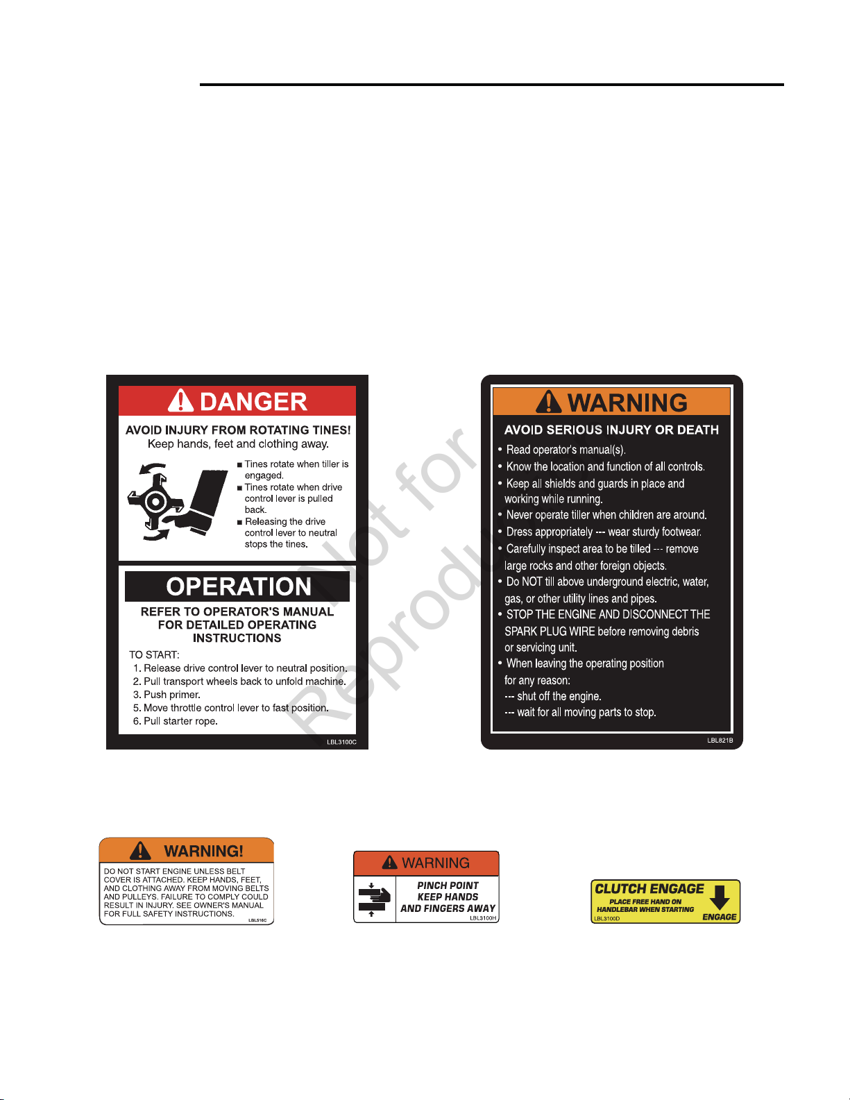
SAFETY DECALS
This rototiller unit has been designed and manufactured to provide you with the safety and reliability you would expect from an industry
leader in outdoor power equipment manufacturing.
Although reading this manual and the safety instructions it contains will provide you with the necessary basic knowledge to operated
this equipment safely and effectively, we have placed several safety labels on the tiller to remind you of this important information
while you are operating the unit.
These important safety labels are illustrated below, and are shown here to help familiarize you with the location and content of the
safety messages you will see as you perform normal tilling operations. Please review these labels now. If you have any questions
regarding their meaning or how to comply with these instructions, reread the complete safety instruction text on the preceding pages,
or contact your local dealer.
Should any of the safety labels become unreadable because of being worn, faded, or otherwise damaged during the use of your tiller,
please use the part number information provided to order a replacement label from your local authorized dealer.
The safety labels are easily applied, and will act as a constant visual reminder to you, and others who may use the equipment. Follow
the safety instructions necessary for safe, effective operation of your rototiller.
Part No. 1737283
TINES DANGER/OPERATION
Hood Decal
Part No. 1737285
WARNING
Belt Cover Decal
Part No. 1737287
WARNING
Pivot Mount Decal
6
Part No. 1737284
HOOD WARNING
Hood Decal
Part No. 1737288
CLUTCH ENGAGE
Handlebar Decal
Page 7

UNPACK TILLER AND ASSEMBLE
Not for
Reproduction
1. Open top of carton and remove handlebar assembly.
2.
Find parts packet. Parts packet contains:
6- 5/16-18 x 1-3/4” bolts
6- 5/16” spring lockwashers
2- hand knobs
4- locknuts
2- 1/2” push nuts
1- detent pin
3. Cut open end of carton and remove machine:
a. Install wheels on each end of axle, tap on push nuts with a
hammer.
b. Assemble tines to unit, inside tines fi rst. Sharp edge of tine
will be away from operator at top or face down at front of
machine.
c. Outside tines have two positions- wide 21” & narrow 16”. For
narrow width - assemble with short side of tine holder pipe
towards center of machine.
d. For wide width - move left tine to right side and right to left
side. Assemble with long half of tine pipe towards machine.
e. Slide top handle of handlebar over lower loop. Put 5/16-18
x 1-3/4” bolts thru both holes from inside out, put on 5/16”
spring lockwashers and tighten with hand knobs.
f. Check upper and lower jam nuts for tightness. See page 9,
Belt Tension Adjustment.
g. Add and check engine oil.
Unpacking and Assembly
IMPORTANT
THE RIGHT AND LEFT SIDES OF YOUR
ROTOTILLER ARE DETERMINED FROM
THE OPERATING POSITION AS YOU
FACE THE DIRECTION OF FORWARD
TRAVEL.
ENGINE IS SHIPPED FROM FACTORY
WITHOUT OIL. YOU MUST ADD ENGINE
OIL BEFORE STARTING ENGINE.
!
CAUTION
DO NOT TRY TO LIFT THE ROTOTILLER FROM THE
CARTON.
NARROW TINE WIDTH
INSTALL DEPTH REGULATOR LEVER
1. Install the depth regulator lever through hole in bracket from the
bottom up with curve to rear of unit and secure with detent pin.
FILL ENGINE CRANKCASE
1. Add oil according to engine manual. Do not overfi ll. Use a clean,
high quality detergent oil. Container must be marked A.P.I. Service
SF - SJ. Use no special additives with recommended oils. Do not
mix oil with gasoline. Oil level must be full. Check the oil level
by removing oil fi ll plug. Oil level should be up to the bottom of the
fi ll plug opening.
2. Always check oil level before starting engine. Refer to engine
manual for capacity and type of oil to use.
WIDE TINE WIDTH
upper
handlebar
lower
handlebar
loop
hand knob
depth
regulator
lever
detent pin
7
Page 8
Features
Not for
Reproduction
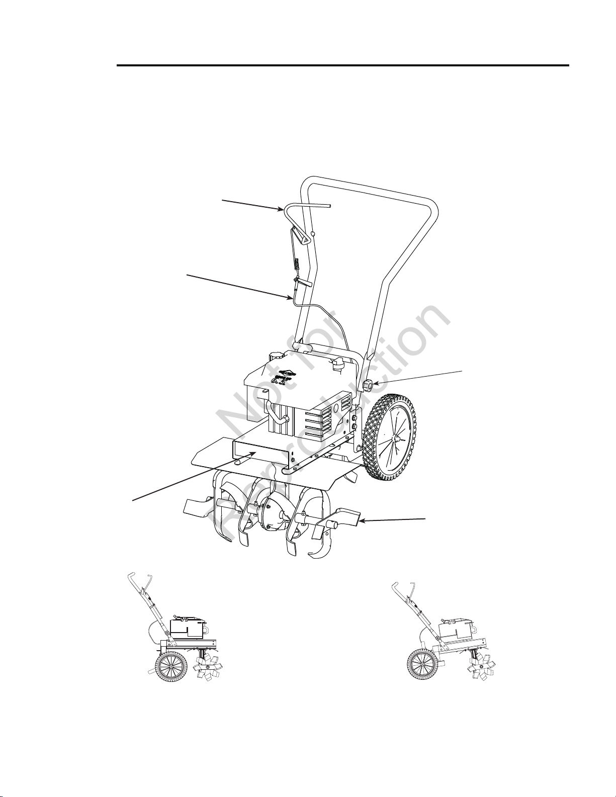
The advantage of the Simplicity/Snapper™ gear drive rototiller over other front tine tillers, is the exclusive unfolding and fl exible drag bar. This gives the gear drive tiller its stability and its versatility. For easy transport, fold
the wheels under the engine. During operation, the wheels unfold back and the drag bar folds down. The long length
between the tines and the drag bar make this the most comfortable front tine tiller on the market.
drive safety control lever
forward cable
front belt cover
hand knob
3-way adjustable tine widths
8
Page 9

Controls
Not for
Reproduction
DRIVE SAFETY CONTROL LEVER
Engage tines into forward, releasing returns machine to neutral.
Pulling down on drive safety control lever engages the tines. Releasing
the drive safety control lever disengages the tines to a neutral
position.
BELT TENSION ADJUSTMENT
Proper belt tension is critical to good performance. After 1/2 hour of
operation, all cables may have to be adjusted due to initial stretch.
Thereafter, check tension after every 2 hours of operation.
To increase belt tension:
1. Loosen upper jam nut. Turn nut up cable in 1/8” increments.
2. Tighten lower jam nut.
3. Check adjustment.
This procedure can be repeated until conduit adjustment bolts have
no more adjustment left. If no more adjustment can be made, belt
may have to be replaced.
DEPTH REGULATOR LEVER
Tilling depth is controlled by the height of the depth regulator lever.
To adjust tilling depth.
1. Remove detent pin.
2. Raise the depth regulator lever to position tines at chosen tilling
depth.
3. Align hole in depth regulator lever with hole in depth regulator
bracket and replace detent pin.
!
CAUTION
THIS INFORMATION IS PROVIDED HERE ONLY TO
INTRODUCE THE CONTROLS. DO NOT START THE
ENGINE AT THIS TIME. STARTING AND OPERATING
INSTRUCTIONS ARE GIVEN ON PAGE 10. PLEASE
READ THIS SECTION AND ALL OPERATING AND
SAFETY INSTRUCTIONS BEFORE STARTING YOUR
TILLER.
s AS A SAFETY PRECAUTION, THE DRIVE SAFETY
CONTROL LEVER WILL NOT LOCK IN THE
FORWARD POSITION.
s TO STOP THE WHEELS AND TINES AT ANY TIME
RELEASE THE DRIVE SAFETY CONTROL LEVER.
!
WARNING
ENGINE SHOULD BE OFF BEFORE ADJUSTING
ANY CONTROLS.
DO NOT ADJUST TILLING DEPTH UNLESS DRIVE
SAFETY CONTROL LEVER IS RELEASED TO THE
NEUTRAL POSITION.
drive safety control lever disengaged
1/4” stretch
upper jam nut
lower jam nut
forward cable
Model 5521 Handlebar
9
Page 10

Operation
Not for
Reproduction
PRE-START INSPECTION
1. Make sure all safety guards are in place and all nuts and bolts
are secure.
2. Check oil level in engine crankcase. See your engine manual for
procedure and specifi cations.
3. Inspect air cleaner for cleanliness. See your engine manual for
procedure.
4. Check the fuel supply. Fill the fuel tank no closer than 1 inch
from top of tank to provide space for expansion. See your engine
manual for fuel recommendations.
5. Be sure spark plug wire is attached and spark plug is
tightened securely.
6. Check position of wheels.
7. Check depth regulator lever position.
8. Examine underneath and around engine for signs of oil or fuel
leaks.
9. Inspect fuel hoses for tightness and fuel seepage.
10. Look for signs of engine damage.
11. Remove excessive debris from muffl er area and recoil starter.
START-UP
The controls required to start and run the rototiller are located on the
engine and are marked “Choke” and “Throttle”.
A more detailed description of engine operation and all related
precautions and procedures can be found in the engine manufacturer’s
manual that accompanies each tiller.
COLD STARTS
1. Move choke lever to full choke position.
2. Move throttle lever to “start”.
3. Pull starting rope out slowly one time and allow to return
normally.
4. Pull starting rope out rapidly, and allow rope to return normally.
5. When engine starts, gradually move choke lever to “no choke”
position and increase throttle speed.
RESTARTING A WARM ENGINE
Restarting an engine that is already warm from previous running does
not normally require use of the choke.
1. Move throttle lever to “start” position.
2. Pull starting rope out rapidly until engine starts. Allow rope to return
normally. Repeat until engine starts.
3. Adjust throttle speed to “high” for best tiller action.
IMPORTANT
ENGINE IS SHIPPED FROM FACTORY WITHOUT OIL.
YOU MUST ADD ENGINE OIL BEFORE STARTING
ENGINE.
PRACTICE OPERATING THE CONTROLS AND
TILLER WITH TINES OUT OF GROUND BEFORE
BEGINNING TO TILL. IT IS IMPORTANT THAT YOU
KNOW HOW TO USE THE TILLER PROPERLY, KEEP
CONTROL AT ALL TIMES, STOP THE TINES AND
WHEELS FROM TURNING, AND STOP THE ENGINE
IF NECESSARY. IF YOU DO NOT KNOW HOW TO
DO THESE THINGS, READ THE CONTROLS AND
SAFETY SECTIONS BEFORE PROCEEDING.
!
CAUTION
PLEASE DO NOT START YOUR TILLER UNTIL YOU
HAVE READ THE MANUAL THAT CAME WITH YOUR
ENGINE, AND THE SECTIONS IN THIS MANUAL
TITLED CONTROLS AND SAFETY. IF YOU HAVE
READ THESE, FOLLOW THE STEPS BELOW TO
START YOUR TILLER. ALWAYS PERFORM THIS
PRE-START CHECKLIST BEFORE STARTING THE
ENGINE.
!
WARNING
GASOLINE IS HIGHLY FLAMMABLE AND MUST
BE HANDLED WITH CARE. NEVER FILL THE TANK
WHEN THE ENGINE IS HOT OR RUNNING. ALWAYS
MOVE OUTDOORS TO FILL THE TANK.
TEMPERATURE OF MUFFLER AND NEAR BY AREAS
MAY EXCEED 150° F. AVOID THESE AREAS.
DO NOT MOVE CHOKE CONTROL TO CHOKE TO
STOP ENGINE. BACKFIRE OR ENGINE DAMAGE
MAY OCCUR.
TO STOP THE ENGINE AT ANY TIME, MOVE THROTTLE CONTROL TO THE OFF POSITION. TO STOP
TINES AT ANY TIME, RELEASE DRIVE SAFETY
CONTROL LEVER TO THE NEUTRAL POSITION.
ALWAYS RELEASE DRIVE SAFETY CONTROL
LEVER TO THE NEUTRAL POSITION BEFORE
ADJUSTING THE DEPTH OF THE REGULATOR
LEVER.
10
Page 11

Operation
Not for
Reproduction
OPERATING SPEED
For normal tilling, set the throttle lever to “fast”.
SHUTTING DOWN
To stop the engine at any time, move throttle control to the off position.
To stop wheels and tines at any time, release the drive safety control
lever to the neutral position.
TILLING
1. Adjust the depth regulator lever to desired tilling depth.
NOTE: Raise depth regulator lever up one hole at a time,
testing tiller operation after each raise. Raising depth regulator
lever too high can result in loss of control of tiller!
2. Move the throttle control to fast.
3. Place the tiller in motion by pushing down on the drive safety control
lever--this will engage the tines.
!
WARNING
EXTREME CAUTION MUST BE TAKEN IN SELECTING TILLING DEPTH. IF YOU ATTEMPT TO TILL
TOO DEEPLY FOR SOIL CONDITIONS, THAT IS,
WITH THE DRAG STAKE IN TOO HIGH A POSITION,
LOSS OF CONTROL COULD RESULT.
IF REMOVING MATERIAL FROM THE TINES BY
HAND, STOP ENGINE AND REMOVE SPARK PLUG
WIRE FIRST.
!
DANGER
ENGINE AND SURROUNDING PARTS BECOME
EXTREMELY HOT DURING NORMAL USE AND WILL
CAUSE SERIOUS BURN INJURIES IF TOUCHED
BEFORE THE ENGINE HAS COOLED.
ALLOW ENGINE TO COOL COMPLETELY BEFORE
TOUCHING THESE HOT SURFACES.
ALWAYS KEEP HANDS AND FEET CLEAR OF
ROTATING MACHINE PARTS.
11
Page 12

Maintenance
Not for
Reproduction
MAINTENANCE SCHEDULE
Your rototiller has been designed and produced by the industry’s leading manufacturer of outdoor power equipment to provide you
with years of reliable operation.
Keeping your tiller in top running condition will prolong its life, and help you obtain optimum performance.
Please read this normal care schedule, and note the recommended care operating intervals to extend the life of your unit.
egaPnoitarepO ecnanetniaM
EM = See engine man
1 Adjust throttle control after fi rst 3 hours of operation or if engine is hard to start or run-on occurs.
2 Change oil after fi rst 5-8 hours of use, then after every 50 hours or every season. Change oil every 25
hours when operating under heavy load or in high temperatures.
ual
Before
Each Use
X31noisnet tleb egnahC
X41tfahs elxa enit naelC
50 hours or
Every Season
X31tleb drawrof egnahC
XX41ecnanetniam enignE
2X41esacknarc enigne ll fi ro kcehC
X41noitacirbuL
1-tnemtsujda lortnoc elttorht kcehC
SERVICING THE ROTOTILLER
The following information will help you make the necessary checks
and perform the procedures required to follow the normal care
recommendations made for your rototiller unit.
If you prefer, your local authorized dealer can make these checks and
perform the required procedures for you.
12
!
WARNING
To prevent accidental starting:
Engine must be turned off and cool, and spark
plug wire must be removed and secured from
spark plug before checking and adjusting engine
or equipment.
Page 13

Maintenance
Not for
Reproduction
CHECK BELT TENSION
Belt tension may decrease over time. It must be adjusted within the
fi rst half hour of operation, and checked after every two hours of
operation. Proper adjustment will assure long belt life. Too much or
too little belt tension will cause premature belt failure. To check and
adjust the forward belt tension:
1. Turn off engine. Engine must be cool.
2. Remove spark plug wire from spark plug and secure.
3. With drive safety control lever in the neutral position, measure
length of spring when in its relaxed state.
4. Pull down on drive safety control lever and measure length of
spring when compressed. Ideal length would be 1/4” shorter.
CHANGE FORWARD BELT
1. Turn off engine. Engine must be cool.
2. Remove spark plug wire from spark plug and secure.
3. Remove front belt cover.
s remove the belt from the engine pulley:
- gently pull the engine recoil rope to rotate the pulley.
- with the pulley turning, force the belt out of the V-groove.
- slide the belt free of the engine pulley.
- pull the belt down and out of the way.
- push the bolt forward and out front of machine.
s install new belt:
- place belt in transmission pulley groove.
- gently pull the engine recoil rope to rotate the pulley while
forcing the belt into the V-groove.
4. Replace front belt cover.
5. Attach spark plug wire.
!
WARNING
CHECK FORWARD BELT TENSION REGULARLY.
TOO MUCH OR TOO LITTLE TENSION WILL CAUSE
PREMATURE BELT FAILURE.
remove belt
from front
13
Page 14
Maintenance
Not for
Reproduction
ENGINE MAINTENANCE
Refer to the engine manual included in your parts packet for
information on engine maintenance. Your engine manual provides
detailed information and a maintenance schedule for performing the
following tasks:
1. Check oil level before each use or after every 8 hours of
operation.
2. Change oil after fi rst 5-8 hours of operation. Change oil while engine
is warm. Refi ll with new oil of recommended grade.
4. Check spark plug yearly or every 100 hours of operation.
5. Service air cleaner.
6. Keep engine and parts clean.
7. Check engine and equipment often for loose nuts and bolts, keep
these items tightened.
CHECK OR FILL ENGINE CRANKCASE
1. Add oil according to engine manual. Do not overfi ll. Use a clean,
high quality detergent oil. Container must be marked A.P.I. Service
SF - SJ. Use no special additives with recommended oils. Do not
mix oil with gasoline. Oil level must be full. Check the oil level
by removing oil fi ll plug. Oil level should be up to the bottom of the
fi ll plug opening on most engines.
2. Always check oil level before starting engine. Refer to engine
manual for capacity and type of oil to use.
IMPORTANT
ENGINE IS SHIPPED FROM FACTORY WITHOUT OIL.
YOU MUST ADD ENGINE OIL BEFORE STARTING
ENGINE.
ENGINE CAN OVERHEAT AND BECOME DAMAGED
IF DEBRIS BLOCKS THE COOLING SYSTEM OR
ROTATING SCREEN.
NEVER RUN ENGINE WITHOUT COMPLETE AIR
CLEANER INSTALLED ON ENGINE.
!
CAUTION
DO NOT OPERATE TILLER BEFORE READING
THE ENGINE MANUAL PROVIDED IN THE PARTS
PACKET.
!
WARNING
TEMPERATURE OF MUFFLER AND NEAR BY AREAS
MAY EXCEED 150° F. AVOID THESE AREAS.
CLEAN TINE AXLE SHAFT
1. Turn off engine. Engine must be cool.
2. Remove spark plug wire and secure from spark plug.
3. Remove all vegetation, string, wire, and other material that may
have accumulated on the axle between the inside set of tines and
the seal on the transmission housing.
4. Replace spark plug wire.
LUBRICATION
Proper lubrication of moving mechanical parts is critical for proper care
and maintenance. Oil the moving parts using a 30 weight oil.
14
Page 15

Maintenance
Not for
Reproduction
PREPARE FOR STORAGE
Follow the steps below to prepare your tiller for storage. Read your
engine manual for detailed instructions on preparing the engine for
storage.
1. Protect wheels and axles from rust:
- Coat the axles lightly with axle grease.
2. Drain fuel system completely following engine manufacturer’s
instructions or add fuel stabilizer to prevent fuel from gumming up
during extended storage period.
3. While engine is still warm, drain the oil from the engine. Refi ll with
fresh oil of the recommended grade.
4. Clean external surfaces, engine and cooling fan.
5. Remove spark plug, pour one ounce of SAE 30 oil into spark plug
hole.
6. Plug hole and pull starter cord slowly to distribute oil evenly in
cylinder head area.
7. Reinstall spark plug.
8. Transport unit to a suitable storage location. If you have chosen to
use a fuel stabilizer and have not drained the fuel system, follow all
safety instructions storage precautions in this manual to prevent the
possibility of fi re from the ignition of gasoline fumes. Remember,
gasoline fumes can travel to distant sources of ignition and ignite,
causing risk of explosion and fi re.
9. If there is any possibility of unauthorized use or tampering, remove
the spark plug and store it in a safe place before storing the rototiller
unit. Be sure to plug the spark plug hole to prevent foreign material
from entering.
!
WARNING
DO NOT STORE TILLER IN AN UNVENTILATED
AREA WHERE FUEL FUMES MAY REACH FLAME,
SPARKS, PILOT LIGHTS OR AN IGNITED OBJECT.
DRAIN FUEL OUTDOORS AWAY FROM ANY
IGNITION SOURCES. USE ONLY APPROVED FUEL
CONTAINERS.
15
Page 16

Truobleshooting and Repair
Not for
Reproduction
TROUBLESHOOTING GUIDE
!
While normal care and routine maintenance will extend the life of
your rototiller, prolonged or constant use may eventually require
that service be performed to allow it to continue operating properly.
The troubleshooting guide below lists the most common problems,
causes and remedies.
WARNING
PRACTICE SAFETY AT ALL TIMES. ENGINE MUST BE
TURNED OFF AND ALLOWED TO COOL, AND SPARK
PLUG WIRE MUST BE DISCONNECTED AND SECURED
BEFORE ATTEMPTING ANY MAINTENANCE OR
REPAIR.
FAILURE TO COMPLY WITH THIS SAFETY
CAN RESULT IN SERIOUS PERSONAL INJURY TO YOU
OR BYSTANDERS.
REQUIREMENT
NOITCA/YDEMERMELBORP
.knat sag ot sag ddA strats ton lliw enignE
s Connect spark plug wire to spark plug
s Throttle must be positioned at choke for a cold start
Engine runs rough, fl oods during operation s Clean or replace air cleaner
at end of season
s Make sure spark plug wire is securely attached to spark
plug
s Drive safety control lever must be released to neutral
to start the engine
regulator
s Clean or replace air cleaner
s Improper carburetor adjustment, take to authorized
engine service center
s Replace spark plug and adjust gap
s Drain and refi ll gas tank and carburetor
Engine will not stop when throttle control is positioned at stop s See engine manual to check and adjust throttle linkage
to start the engine
Tiller is diffi cult to control when tilling
(machine jumps or lurches forw
Excessive heat build up in transmission/tine area during tilling
ard)
s Lower engine speed in hard ground
s Raise the tines for shallower tilling by lowering the
depth regulator lever
- turn engine off and allow muffl er to cool
- disconnect spark plug wire and secure from spark plug
- pull down on drive safety control lever
- manually bend forward belt guide so there is 1/16 inch
or less clearance between belt guide and belt
- replace spark plug wire
s$ISCONNECTSPAr
s2ELEASEDrive safety control lever to neutral
s!DJUSTENGAGECAble
s2EPLACESPArk plug wire
s2EMove vegetation
s#HEck transmission fl uid and fi ll if needed
lever
evirD sgnitrats gnirud drawrof sevom relliT
:ediug tleb drawrof tsujdA slartuen ni laeuqs stleB
looc ot re flfum wolla dna ffo enigne nruT snoitarepo drawrof ni laeuqs stleB
k plug wire and secure from spark plug
rezilibats sag esU .hserf htiw ecalper dna leuf dlo niarD strats ot drah si enignE
htped eht gnisiar yb gnillit wollahs rof senit eht esiaR srewop skcal ro sessim enignE
lartuen ot desaeler eb tsum revel lortnoc ytefas
16
Page 17

Additional Technical Literature Available
Not for
Reproduction
Additional copies of this manual are available, as well as
fully illustrated parts lists. These manuals show all of the
product’s components in exploded views (3D illustrations
which show the relationship of parts and how they go
together) as well as part numbers and quantities used.
Important assembly notes and and torque values are
also included.
Technical manuals can be downloaded from:
www.simplicitymfg.com
www.snapper.com.
Technical Manuals
17
Page 18

Not for
Reproduction
18
Page 19

Not for
Reproduction
19
Page 20

www.simplicitymfg.com
Not for
Reproduction
www.snapper.com
Briggs & Stratton Power Products Group, L.L.C.
Copyright © 2008 Briggs & Stratton Corporation
Milwaukee, WI USA. All Rights Reserved
www.BRIGGSandSTRATTON.com
 Loading...