

Page 1

Bimplicilq
OPERATOR'S
MANUAL
FAST-Vac Grass Collection System
48" Collection System 61" Collection System
Contains: Contains:
Mfg. No. Description Mfg. No. Description
3063374 FAST-Vac Blower 3063374 FAST-Vac Blower
5300017 Bagger Mount Adapter 5046864 3-Bag Hood & Mount
5046864 3-Bag Hood & Mount 5300027 Blower Mount
5300025 Blower Mount 5046869 Weight Mount
5300011 Weight Mount 1692939 50 Ibs. Weight (3)
1692939 50 Ibs. Weight (3)
52" Collection System
Contains:
Mfg. No. Description
3063374 FAST-Vac Blower
5300017 Bagger Mount Adapter
5046864 3-Bag Hood & Mount
5300026 Blower Mount
5300011 Weight Mount
1692939 50 Ibs. Weight (3)
5100251-00
Rev 6/2005
TP 100-7235-00-AT-S
Page 2

TableofContents
SAFETY RULES & INFORMATION ..................... 2
Safety Decals .......................................................... 3
GENERAL OPERATING INSTRUCTIONS ........... 4
Before Operation ..................................................... 4
Mowing with the Double / Triple Catcher ................ 4
After Operation ........................................................ 5
Storing the Grass Catcher ...................................... 5
Mowing Without the Blower .................................... 5
INSTALLATION ..................................................... 6
Blower Assembly ..................................................... 6
Mower Deck Preparation ........................................ 8
Blower Installation................................................. 11
Collector Installation.............................................. 13
Weight Mount Installation...................................... 17
BLOWER & COLLECTOR REMOVAL ............... 19
Page 3
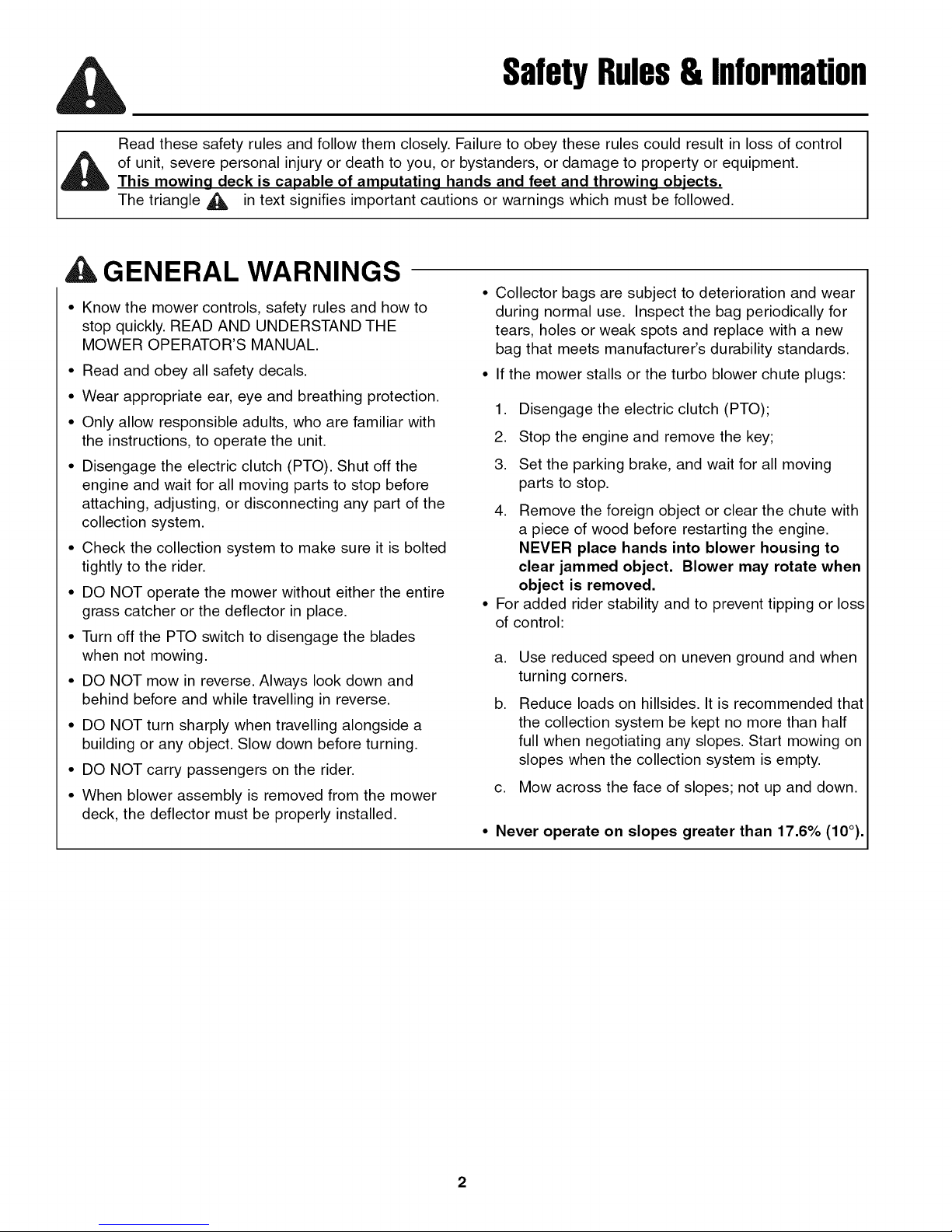
Read these safety rules and follow them closely. Failure to obey these rules could result in loss of control
of unit, severe personal injury or death to you, or bystanders, or damage to property or equipment.
This mowing deck is capable of amputating hands and feet and throwing objects.
The triangle ,d_ in text signifies important cautions or warnings which must be followed.
A GENERAL WARNINGS
• Know the mower controls, safety rules and how to
stop quickly. READ AND UNDERSTAND THE
MOWER OPERATOR'S MANUAL.
• Read and obey all safety decals.
• Wear appropriate ear, eye and breathing protection.
• Only allow responsible adults, who are familiar with
the instructions, to operate the unit.
• Disengage the electric clutch (PTO). Shut off the
engine and wait for all moving parts to stop before
attaching, adjusting, or disconnecting any part of the
collection system.
• Check the collection system to make sure it is bolted
tightly to the rider.
• DO NOT operate the mower without either the entire
grass catcher or the deflector in place.
• Turn off the PTO switch to disengage the blades
when not mowing.
• DO NOT mow in reverse. Always look down and
behind before and while travelling in reverse.
• DO NOT turn sharply when travelling alongside a
building or any object. Slow down before turning.
• DO NOT carry passengers on the rider.
• When blower assembly is removed from the mower
deck, the deflector must be properly installed.
SafetyRules& Information
• Collector bags are subject to deterioration and wear
during normal use. Inspect the bag periodically for
tears, holes or weak spots and replace with a new
bag that meets manufacturer's durability standards.
• If the mower stalls or the turbo blower chute plugs:
1. Disengage the electric clutch (PTO);
2. Stop the engine and remove the key;
3. Set the parking brake, and wait for all moving
parts to stop.
4. Remove the foreign object or clear the chute with
a piece of wood before restarting the engine.
NEVER place hands into blower housing to
clear jammed object. Blower may rotate when
object is removed.
• For added rider stability and to prevent tipping or loss
of control:
a,
Use reduced speed on uneven ground and when
turning corners.
b,
Reduce loads on hillsides. It is recommended that
the collection system be kept no more than half
full when negotiating any slopes. Start mowing on
slopes when the collection system is empty.
c. Mow across the face of slopes; not up and down.
• Never operate on slopes greater than 17.6% (10°).
Page 4
SAFETY DECALS
SafetyDecals
This unit has been designed and manufactured to pro-
vide you with the safety and reliability you would expect
from an industry leader in outdoor power equipment
manufacturing.
Although reading this manual and the safety instructions
it contains will provide you with the necessary basic
knowledge to operate this equipment safely and effec-
tively, we have placed several safety labels on the unit to
remind you of this important information while you are
operating your unit.
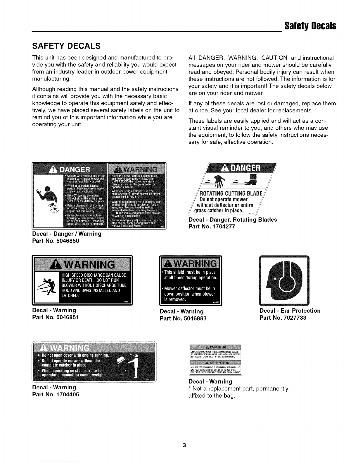
Decal - Danger / Warning
Part No. 5046850
All DANGER, WARNING, CAUTION and instructional
messages on your rider and mower should be carefully
read and obeyed. Personal bodily injury can result when
these instructions are not followed. The information is for
your safety and it is important! The safety decals below
are on your rider and mower.
If any of these decals are lost or damaged, replace them
at once. See your local dealer for replacements.
These labels are easily applied and will act as a con-
stant visual reminder to you, and others who may use
the equipment, to follow the safety instructions neces-
sary for safe, effective operation.
m /
C LADEi
Donotoperatemower /"
withoutdeflect0ror entire /."
grasscatcherinplace. _"
Decal - Danger, Rotating Blades
Part No. 1704277
Decal - Warning
Part No. 5046851
Decal - Warning
Part No. 1704405
Decal - Warning
Part No. 5046883
u E e U G Iss I Ise c
Decal - Warning
* Not a replacement part, permanently
affixed to the bag.
3
Decal - Ear Protection
Part No. 7027733
Page 5

GeneralOperatingInstructions
BEFORE OPERATION
Clear the lawn of all sticks, stones, wire and other debris
which may be caught or thrown by the mower blades.
Check grass condition. If wet, wait until later in the day.
If grass is wet, the grass catcher is likely to become
plugged.
For efficient bagging, air circulation under the
mower deck, through the chute and into the bag is
very important.
For this reason, BEFORE YOU BEGIN MOWING you
should make certain the underside of the mower and
the underside of the catcher lid are free from grass and
debris.
Make sure that there is a snug fit between mower
deck, blower housing, tubes, and grass catcher cover.
MOWING WITH THE DOUBLE/TRIPLE
CATCHER
Always operate with throttle at full speed when mowing.
Always wear hearing protection when operating
grass catcher.
Grass should be cut often, and not too short. If grass is
too long or lush it may be necessary to keep ground
speed to a minimum or to cut only half the width of the
mower to prevent clogging. If grass is long, operate with
mower in high cutting position for first pass, cutting again
in a lower position on a second pass.
Do not open the cover with mower engaged.
If a large amount of cut grass is spilling out from under
deck, the tube may be plugged or the bags may be full.
Discontinue mowing, stop the rider, disengage the PTO
and then empty the catcher or clear the tube.
tLWARNING
ALWAYS shut off the tractor. Disengage the PTO,
and allow all moving parts to stop BEFORE
disconnecting or clearing tube, or emptying
catcher.
Before leaving the operator's position for any
reason, engage the parking brake, disengage the
PTO, stop the engine and remove the key.
To reduce fire hazard, keep the engine, rider and
mower free of grass, leaves and excess grease.
Do not stop or park rider over dry leaves, grass or
combustible materials.
CAUTION
This machine produces sound levels in
excess of 85 dBA at the operator's ear and
can cause hearing loss though extended
periods of exposure.
Wear hearing protection when operating this
machine.
Page 6
AFTER OPERATION
Remove any debris from the the screen on the under-
side of the lid. Note: The lid screen can be partially
removed for easier cleaning and should be cleaned reg-
ularly.
The blower housing and tube should be removed for
cleaning.
Inspect the grass bags for wear or damage. Make sure
that there is a snug fit between mower deck, blower
housing, tubes, and grass catcher cover.
STORING THE GRASS CATCHER
Clean the grass catcher thoroughly using a mild deter-
gent (other products may damage the tube). Remove
any debris from the the screen on the underside of the
lid. The screen can be partially removed for easier clean-
ing.
If paint has been scratched on metal parts, touch up
with paint, or apply a thin film of oil to prevent corrosion.
GeneralOperatinginstructions
Store in a dry area. Hang the catcher and catcher bags
to dry thoroughly before storing for a long period of time.
Always store away from moisture.
MOWING WITHOUT THE BLOWER
For operation without the blower, the deflector must be
properly installed in the down position.
To remove the blower, see BLOWER & COLLECTOR
REMOVAL on page 19.
5
Page 7

BlowerAssembly
1. Remove the existing 5/16-18 x 5/8" flange head bolts
(B, Figure 1) from the blower housing (A).
2. Install the blower mount plate (C) onto the blower
housing and reinstall the 5/16-18 x 5/8" flange head
bolts. Tighten securely.
3. Install three (3) 3/8-16 x 1" bolts and nylon lock nuts
(D) through the blower mount plate and blower. The
bolt heads must be installed on the inside of the
blower housing.
\
f
Figure 1. Install Blower Mount Plate
A. Blower Housing
B. 5/16-18 x 5/8" Bolts (existing)
C. Blower Mount Plate
D. 3/8-16 x 1" Bolts & Nylon Lock Nuts (3X)
4. Loop the idler spring (A, Figure 2) through the 1/4" x
2" eyebolt (B). Install the eyebolt through the L-
bracket on the blower mount and install the 1/4-20
nylock flange nut (C). Tighten the nut until the eye-
bolt contacts the L-bracket.
Figure 2. Install Idler Spring
A. Idler Spring
B. 1/4" x 2" Eyebolt
C. 1/4-20 Nylock Flange Nut
Page 8

BlowerAssembly
5. Remove the blower belt guard and set aside.
6. Install the impeller drive pulley (A, Figure 3) onto the
impeller shaft (B) as described in Figure 3. Install
the 1/4" x 1-1/2" long key (not shown) in the pulley.
7. Align the pulley groove with the appropriate slot as
described in Figure 3. Tighten the set screws in the
pulley.
8. Reposition the 3/8-16 x 6" bolt if required to line up
with the pulley groove.
Inner Slot
Figure 3.
/[ Y
Hub pointing IN:
48" Model
Install Impeller Drive Pulley
Flub pointing OUT:
52" Model
61" Model
©
Align pulley groove
with slot (outer slot
with pulley hub in
OR inner slot with
pulley hub out)
Outer Slot
,
Check the position of the idler pulley (A, Figure 4).
The position must be aligned with the position of the
pulley (outer row of holes for pulley hub pointing in,
inner row of holes for pulley hub pointing out).
Reposition if necessary.
Outer
_ _lnner Row
Figure 4. Check Idler Pulley Position
A. Idler Pulley
7
Page 9

MowerDeckPreparation
Remove the Discharge Chute
1. Remove the discharge chute (A, Figure 5), chute
mount rod (B), torsion spring (C), 5/16" fender wash-
er (D), spring spacer (E) and all mounting hardware.
2. Save the spring, fender washer, spacer as they will
be used later when the blower is removed.
3. Remove the deck guard (F). Save the bolts and
washers, as they will be required in a later step.
Figure 5. Remove Chute & Guard
A. Discharge Chute
B. Chute Mount Rod
C. Torsion Spring
D. 5/16" Fender Washer
E. Spring Spacer
R Deck Guard
4. Examine the discharge chute mount bracket on the
mower deck (see Figure 6). If the hole pattern looks
like the one shown, you must drill a 3/8" hole in the
location specified in Figure 6.
Figure 6. Discharge Chute Mount
Page 10

Remove the Spindle Belt
Citation Series:
,
Using a 1/2" breaker bar, place the square end in the
square hole located in the end of the idler arm (A,
Figures 7). Carefully rotate the breaker bar clock-
wise, which will relieve the tension on the belt exert-
ed from the idler arm.
,
Slide the drive belt over the edge of the stationary
idler pulley (B). Carefully release the tension on the
breaker bar. Remove the belt from the right-hand
(discharge side) spindle pulley.
Stallion Series:
,
Using a 1/2" breaker bar, place the square end in the
square hole located in the end of the idler arm (A,
Figures 8). Carefully rotate the breaker bar counter-
clockwise, which will relieve the tension on the belt
exerted from the idler arm.
,
Slide the drive belt over the edge of the stationary
idler pulley (B). Carefully release the tension on the
breaker bar. Remove the belt from the right-hand
(discharge side) spindle pulley.
MowerDeckPreparation
Figure 7. Mower PTO Belt
A. Idler Arm
B. Stationary Idler Pulley
AWARNING
Use extreme caution when rotating the idler arm
with the breaker bar, due to the increased tension
in the spring as the idler arm is being rotated.
Injury may result if the breaker bar is prematurely
released while the spring is under tension.
Figure 8. Mower PTO Belt
A. Idler Arm
B. Stationary Idler Pulley
9
Page 11

MowerDeckPreparation
Remove the Spindle Pulley
1. Remove the 3/4-16 hex nut & 3/4" spring washer (A
& B, Figure 9) securing the spindle pulley (C) to the
spindle shaft. Use a 1" wrench on the flats of the
blade end of the spindle shaft to prevent the shaft
from spinning. Save the 1/4" key (D).
Figure 9. Remove Spindle Pulley
A. 3/4-16 Hex Nut
B. 3/4" Spring Washer
C. Spindle Pulley
D. 1/4" Key
Install the Double Spindle Pulley
1. Install the double spindle pulley (C, Figure 10) and
1/4" key (D) onto the spindle shaft.
2. Install the 3/4" spring washer (B) with the cone facing
up (see insert, Figure 10). Install the 3/4-16 hex nut
(A) and torque to 85-90 ft. Ibs (115-122 Nm). Use a
1" wrench on the flats of the blade end of the spindle
shaft to prevent the shaft from spinning.
Reinstall the Spindle Belt
Refer to the belt removal instructions on Page 9 and
reverse the order for reinstalling the belt.
I
\
Figure 10. Install Double Spindle Pulley
A. 3/4-16 Hex Nut
B. 3/4" Spring Washer
C. Double Spindle Pulley
D. 1/4" Key
1
Install the Deck Guard
1. Install the new deck guard onto the mower deck and
secure with the hardware previously removed (see
Figure 11).
Figure 11. Install Guard
10
Page 12

BlowerInstallation
, Install the blower onto the mower deck. Refer to
Figure 12 for the position of the quick pins in relation-
ship to the chute mount bracket on the mower deck.
The quick pins fit into the same holes that the chute
mount rod was installed.
\ 0!
48" & 52" Decks
61" Deck
Figure 12. Install Blower On Deck
2. Install the blower drive belt. Refer to Figure 13 for
the proper belt routing. It may be required to loosen
the idler pulley mounting hardware to get the belt
past the belt keeps.
IMPORTANT NOTE: The gray area denotes the flat side
of the belt. V-side of belt must contact v-groove pulleys,
flat side of belt must contact flat pulleys.
©
Figure 13. Install Belt
11
Page 13

BlowerInstallation
3. Check the belt tension by measuring the distance
from the center of the v-idler pulley (A, Figure 14)
mounting bolt and the blower housing. This should
measure between 3 - 3-3/8" (7,6 - 8,6 cm).
4. If measurement falls outside of this range, you must
move the idler pulley (B) either forward or back to
achieve the proper belt tension.
NOTE: If pulley position needs to be adjusted, make
sure that it is reinstalled in the same row of holes as
determined in the blower assembly (Step 9, page 7).
Figure 14. Check Belt Tension
A. V-Idler Pulley
B. Idler Pulley
5. Install the blower belt guard (A, Figure 15) and
secure with the flange head bolts previously
removed.
6. Install the deck guard top (B) and secure with the
supplied knobs (C).
®
Figure 15. Install Guards
A. Blower Belt Guard
B. Deck GuardTop
C. Knob
12
Page 14

Install Mount Plate
(Citation Models)
1. Install the adapter plate (A, Figure 16) onto the
mount plate (B) and secure with the 3/8-16 x 1" bolts
(C) and 3/8-16 nylock flange nuts (D).
2. Install the mount plate onto the bumper.
3. Install the mount spacers (E) between the adapter
plate and mount plate, as shown, and loosely secure
with the 3/8-16 x 2-1/2" bolts (F) and 3/8-16 nylock
flange nuts (D).
4. Install the 3/8" U-bolts (G) on the bottom bumper
tube and through the mount plate. Loosely install the
3/8-16 nylock flange nuts (D).
5. Center the mount plate, side-to-side, on the bumper
tubes and tighten hardware securely.
Collectorinstallation
©
Figure 16. Install Mount Plate - Citation
A. Adapter Plate
B. Mount Plate
C. 3/8-16 x 1" Bolts
D. 3/8-16 Nylock Flange Nuts
E. Mount Spacers
F. 3/8-16 x 2-1/2" Bolts
G. 3/8" U-Bolts
Install Mount Plate
(Stallion Models)
1. Install the mount plate (A, Figure 17) on the bumper
using four 3/8-16 x 1" bolts (B) and 3/8-16 flange
nuts (C). Tighten hardware securely.
Figure 16. Install Mount Plate - Stallion
A. Mount Plate
B. 3/8-16 x 1" Bolts
C. 3/8-16 Flange Nuts
13
Page 15

Collectorinstallation
Assemble Back Plate & Mount Frame
1. Attach the back plate (A, Figure 18) to the mount
frame (B) using carriage bolts, flat washers, and
nuts. Use two 5/16-18 x 3/4" carriage bolts (D) in the
top two holes, and two 5/16-18 x 1-1/4" carriage
bolts (E) in the bottom holes.
2. Install the cover latch (H, Figure 18) and reinforce-
ment plate (G). Secure with two 5/16-18 x 3/4" bolts
(F), and 5/16-18 serrated flange nuts (J).
3. Mount the back plate to the support assembly and
secure with the long hitch pin (K, Figure 18) and hair
pin clip (L).
Figure 18. Install Back Plate
A. Back Plate
B. Mount Frame
C. 5/16-18 Nylon Lock Nuts
D. 5/16-18 x 3/4 Carriage Bolts
E. 5/16-18 x 1-1/4 Carriage Bolts
F. 5/16-18 x 1 Bolts
G. Latch Reinforcement Plate
H. Cover Latch
I. 5/16" Flat Washers
J. 5/16-18 Serrated Flange Nuts
K. Hitch Pin
L. Hair Pin Clip
14
Page 16

Figure 19. Install Deflector & Hose
Collectorinstallation
%
G. Hose, 55" Long
H. Lower Hose Clamp
Install Deflector & Hose
1. Install the deflector (A, Figure 19) and hose adapter
(D), with the tube pointing down, to the back plate
and secure with four 5/16-18 x 1" bolts (E), 5/16"
washers (C) and 5/16-18 nylon lock nuts (B).
2. Install the hose (G) onto the blower and secure with
the removable clamp (with knob) (H). At least two
bands must cover the outlet of the blower.
3. Cut the hose to fit properly between the blower and
collector. At least two bands must cover the inlet of
the adapter (D). Secure with the stationary clamp
(F)
4. Remove the valve stem covers and increase the rear
drive tire air pressure to 22 psi (151 kPa). Reinstall
the valve stem covers.
15
Page 17

Collectorinstallation
Install Cover
1. See Figure 20. Hook the bags (A) on the back plate
(B). Note: If desired, the bags can be lined with 30
gallon trash bags for easy disposal
2. See Figure 21. Set the cover (A) on top of the bags
(B) and align the hinges (C).
3. See Figure 22. Install the hinge pins (B) through the
the hinges (C) and secure with a hair pin clip (D).
NOTE: Push the hair pin clip all the way on or it will be
bent by the hinge when the cover is opened.
4. Secure the cover by connecting the rubber strap to
the cover latch (H, Figure 23).
Figure 20. Install the Bags
A. Bags
B. Back Plate
Figure 21. Install Cover
A. Cover
B. Bags
C. Hinges
Figure 22. Install Hinge Pins
A. Cover C. Hinge
B. Hinge Pin D. Hair Pin Clip
16
Page 18

Install Weight Carrier
1. Install the weight carrier (A, Figure 23) onto the front
of the unit and secure with the 1/2-20 x 1-1/4" bolts
(B), 1/2" washers (C) and 1/2-20 nylon lock nuts (D).
NOTE: Use outer holes in the weight carrier for the
IS1500Z Series (shown) and the inner holes for the
IS4500Z Series.
2. Install the counter weights (E) in the weight carrier
and secure with the retaining pin (F) and hairpin clips
(G).
®
WeightMountInstallation
(CitationSeries)
Figure 23. Install Weight Carrier
A. Weight Carrier
B. 1/2-20 x 1-1/4" Bolt
C. 1/2" SAE Washer
D. 1/2-20 Nylon Lock Nut
E. Weight
E Retaining Pin
G. Hairpin Clip
J
/
/
/
17
Page 19

WeightMountInstallation
(StallionSeries)
Install Weight Mount Rack
1. Measure and mark the front main frame tubes to the
dimensions shown in Figure 24.
2. Using a 3/8" drill bit, drill one (1) hole in each of the
main frame tubes from the outside surface of the
tube.
Figure 24. Hole Location
3. Slide the weight mount rack into the main frame
tubes and align with the holes drilled through the
frame (see Figure 25). It may require you drive the
arms into the frame tubes using a wooden block and
hammer.
4. Finish drilling through the opposite wall of the frame
tubes using the weight rack as a guide.
5. Install the 3/8" bolts from the inside of the frame rail
and fasten securely with the nylon lock nuts.
6. Install the counter weights supplied with the grass
collector on the weight mount rack (see Figure 26).
7. Install the weight retainer rod through the weight
mount rack and secure with the hairpin clips (see
Figure 26).
I..................
Figure 25. Weight Rack Installation
Figure 26. Weight & Retainer Rod Installation
18
Page 20

1. Remove the knobs (A, Figure 27) securing the deck
guard top (B) to the deck guard.
2. Pull the blower idler arm lever (C) forward to release
the belt tension and remove the belt from the spindle
pulley.
3. Reinstall the deck guard top and secure with the
knobs.
Blower& CollectorRemoval
Figure 27. Remove Belt
A. Knob
B. Deck GuardTop
C. Idler Arm Lever
4. Loosen the lower clamp securing the hose to the
blower outlet and remove the hose from the blower.
See Figure 28.
5. Pull the quick pins on the blower mount and remove
the blower from the mower deck.
Figure 28. Remove Hose
A. Lower Clamp
19
Page 21

Blower& CollectorRemoval
6. Reinstall the discharge chute (A, Figure 29), torsion
spring (B), 5/16" fender washer (C), spring spacer
(D) and secure with the supplied quick attach rod (E)
and hairpin clips (F).
7. Empty the grass collector bags and reinstall in the
bagger frame.
Figure 29. Reinstall Discharge Chute
A. Discharge Chute
B. Torsion Spring
C. 5/16" Fender Washer
D. Spring Spacer
E. Quick Attach Rod
E Hairpin Clip
8. Remove the hitch pin (A, Figure 30) and hair pin clip
(B) securing the mount frame (C) to the mount plate.
9. Lift the bagger unit up and off of the mount plate.
Figure 30. Remove Hitch Pins
A. Hitch Pin
B. Hair Pin Clip
C. Mount Frame
20
Page 22

MANUFACTURING, INC.
500 N Spring Street / PO Box 997
Port Washington, Wl 53074-0997
www.simplicitymfg.com
© Copyright 2005, Simplicity Manufacturing, Inc.
All Rights Reserved. Printed in USA.
 Loading...