

Page 1
Parts Manual
Rev. 2/1995
TP 400-1399-02-RG-SMA
(Includes TP-1401 & TP-1402)
REGENT / 500 / 2500
SERIES LAWN TRACTORS & MOWER DECKS
12.5HP GEAR TRACTORS
Mfg. No. Description
1692401 Regent 12.5HP Gear
1692405 Regent 12.5HP Gear (Export)
1692409 512G, 12.5HP Gear
1692493 2513G, 12.5HP Gear
12.5HP HYDRO TRACTORS
Mfg. No. Description
1692403 Regent 12.5HP Hydro
1692407 Regent 12HP Hydro (Export)
1692412 512H, 12HP Hydro
1692495 2512H, 12HP Hydro
36” MOWER DECKS
1692366 36” Mower Deck
1692410 36” Mower Deck
Page 2

© Copyright 1995 Simplicity Manufacturing, Inc.
All Rights Reserved. Printed In USA.
MANUFACTURING, INC.
500 N Spring Street / PO Box 997
Port Washington, WI 53074-0997 USA
Page 3

FRAME................................................................................................................................................................2
FRONT AXLE .....................................................................................................................................................4
STEERING..........................................................................................................................................................6
ENGINE...............................................................................................................................................................8
GEAR TRANSAXLE - Peerless Model 930-039 .............................................................................................10
HYDRO TRANSAXLE - Hydro Gear Model 318-0500
Group 1..........................................................................................................................................................12
Group 2..........................................................................................................................................................14
BRAKE & CLUTCH
Gear ...............................................................................................................................................................16
Hydro.............................................................................................................................................................18
ELECTRICAL
Gear ...............................................................................................................................................................20
Hydro.............................................................................................................................................................22
HOOD, DASH & FUEL TANK ..........................................................................................................................24
SEAT & DECK..................................................................................................................................................26
FRONT WHEELS & TIRES ..............................................................................................................................28
REAR WHEELS & TIRES.................................................................................................................................30
DECALS
Simplicity.......................................................................................................................................................32
AGCO Allis....................................................................................................................................................34
Massey Ferguson.........................................................................................................................................36
36" MOWER DECK
Deck, Arbor & Blades...................................................................................................................................38
Clutch & Roller Support...............................................................................................................................42
Rollers & Miscellaneous..............................................................................................................................46
GEAR TRANSAXLE SERVICE PARTS - Peerless Model 930-039 ...............................................................48
HYDRO TRANSAXLE SERVICE PARTS - Hydro Gear Model 318-0500......................................................52
PART NUMBER INDEX ...................................................................................................................................A1
TORQUE SPECIFICATION CHART................................................................................................LAST PAGE
1
Table of Contents
Page 4
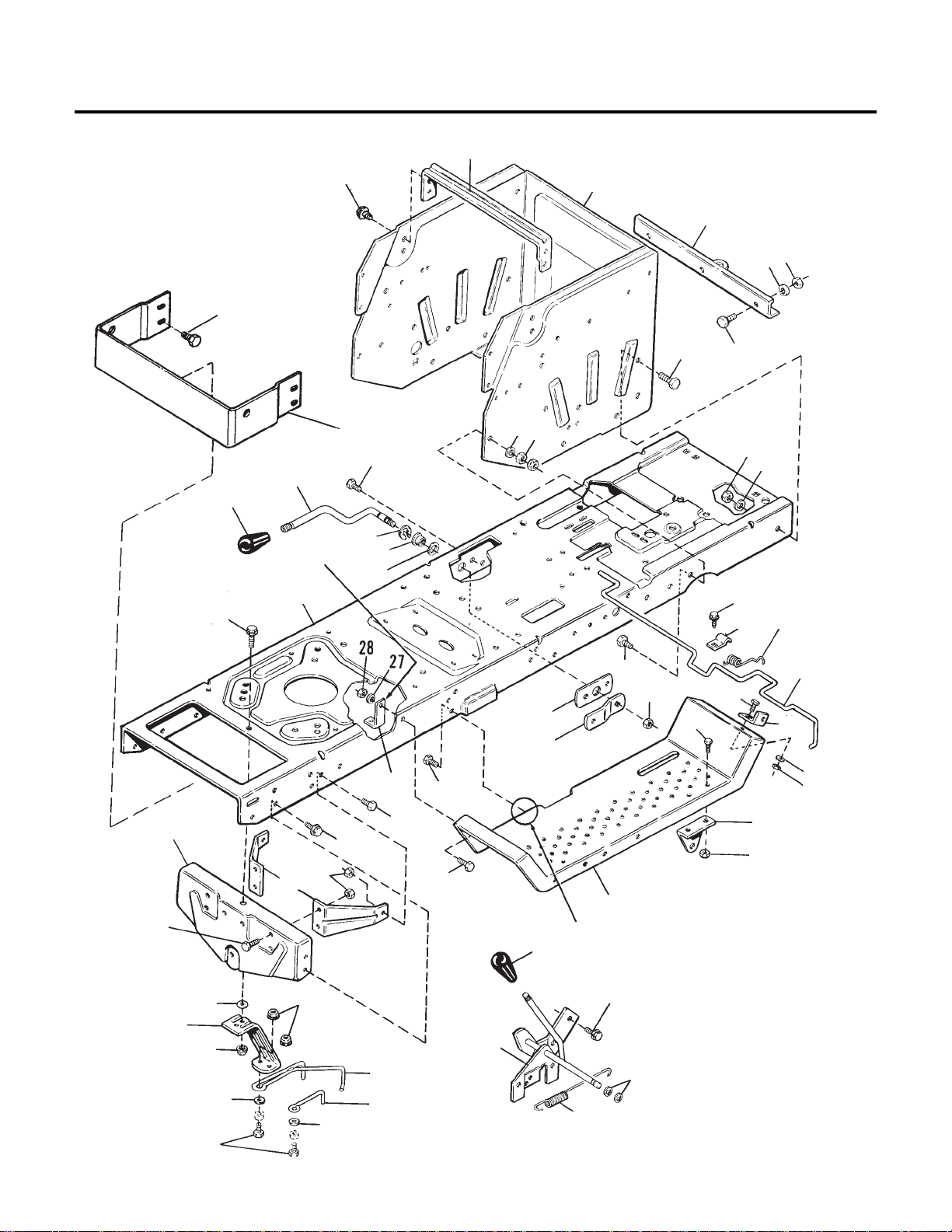
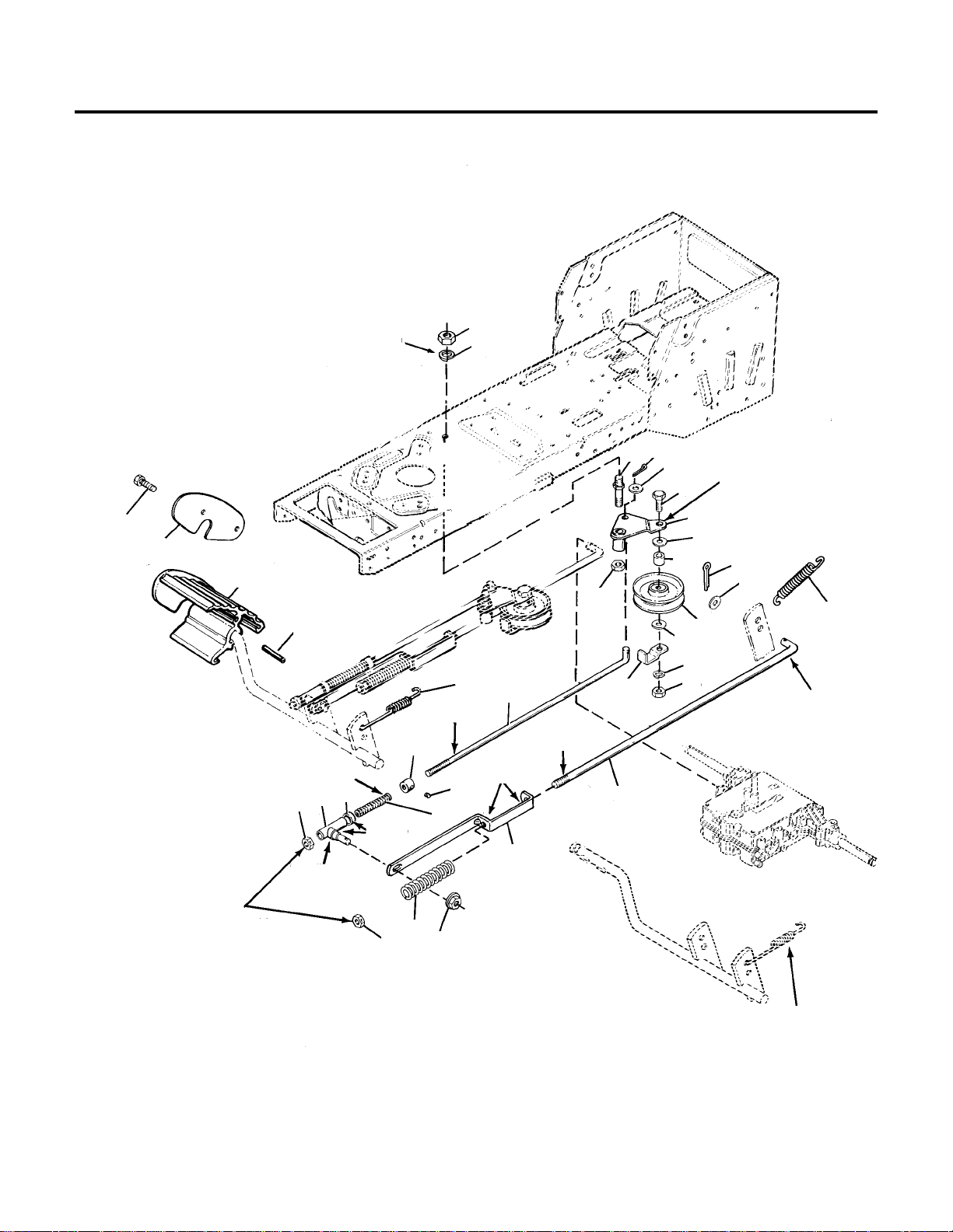
2
Frame
NOTE: Unless noted otherwise, use the standard hardware torque specification
chart. See the Table of
Contents
**2405
3
20
6
31
30
40
36
31
30
30
42
31
42
16
19
18
13
17
37
29
4
29
25
26
38
38
8
30
36
7
38
23
43
1
15
27
34
41
34
44
12
35
38
10
5
33
11
45
24
26
28
9
42
11
2
21
13
14
44
Assemble screw in this
location with head to the
inside.
22
Hydro Models
Only
39
Page 5

1 158399 2 RING, Retaining
2 960171 1 WASHER
3 1654707 1 BRACE, Seat
4 1654783 1 SUPPORT, Clutch
5 1655076 2 BRACE, Axle Support
6 1655591 1 BAR, Draw
7 1656754 1 BAR, Support
8 1656755 1 ARM, Support
9 1656791 1 SUPPORT, Hood (Gear models only)
10 1664034 1 SUPPORT, Axle
11 1664847 2 SCREW, Taptite, 5/16-18 x 3/4 (Qty. 6 used on hydro models)
12 1665803 1 SUPPORT
13 1665812 1 STOP, Belt
14 1672118 1 STOP, Belt
15 1673911 1 SPRING, Extension
16 1678388 2 CLIP
17 1700670 1 BRACKET, Seat Latch
18 1701268 1 ROD, Latch (Hydro Models)
19 1701314 1 SPRING, Torsion
20 1702627 1 SUPPORT, Axle Wrapper
21 1703805 1 KLIPRING, 1/2
22 1704505 1 BUSHING
23 1705873 1 BRACKET, Spring (Hydro models only)
24 1708723 1 FRAME
25 1709280 2 FOOTREST
26 1713843 2 KNOB, Handle
27 1713853 1 HANDLE ASSY., PTO Clutch
28 1713856 1 HANDLE, Lift
29 1916622 3 NUT, Hex, 1/4-20
30 1916950 10 NUT, Hex, 3/8-16
31 1916965 9 LOCKWASHER, 3/8
32 1917356 8 LOCKWASHER, 5/16 (Qty. 9 used on hydro models
33 1917372 14 NUT, Hex, Full, 5/16-18 (Qty. 18 on hydro models)
34 1919326 2 WASHER, 11/32
35 1919381 1 WASHER, Plain, 11/32-1 x 10 Ga.
36 1921210 10 CAPSCREW, Hex, 3/8-16 x 1 (Qty. 9 used on hydro models)
37 1921319 1 WASHER
38 1921332 14 CAPSCREW, Hex, 5/16-18 x 3/4
39 1921959 3 CAPSCREW, Hex, 1/4-20 x 5/8
40 1921965 3 CAPSCREW, Hex, 3/8-16 x 3/4
41 1923325 2 CAPSCREW, Hex, 5/16-18 x 7/8
42 1924856 6 SCREW, Taptite, 5/16-18 x 1/2
(Qty. 8 on hydro models)
43 1925003 2 SCREW
44 1927557 3 LOCKNUT, Hex, Flange Whiz, 5/16-18
45 1930595 1 CAPSCREW, Hex Flange Hd., 5/16-18 x 1-1/4
3
REF. PART
NO. NO. QTY. DESCRIPTION
All Models
Frame
Page 6
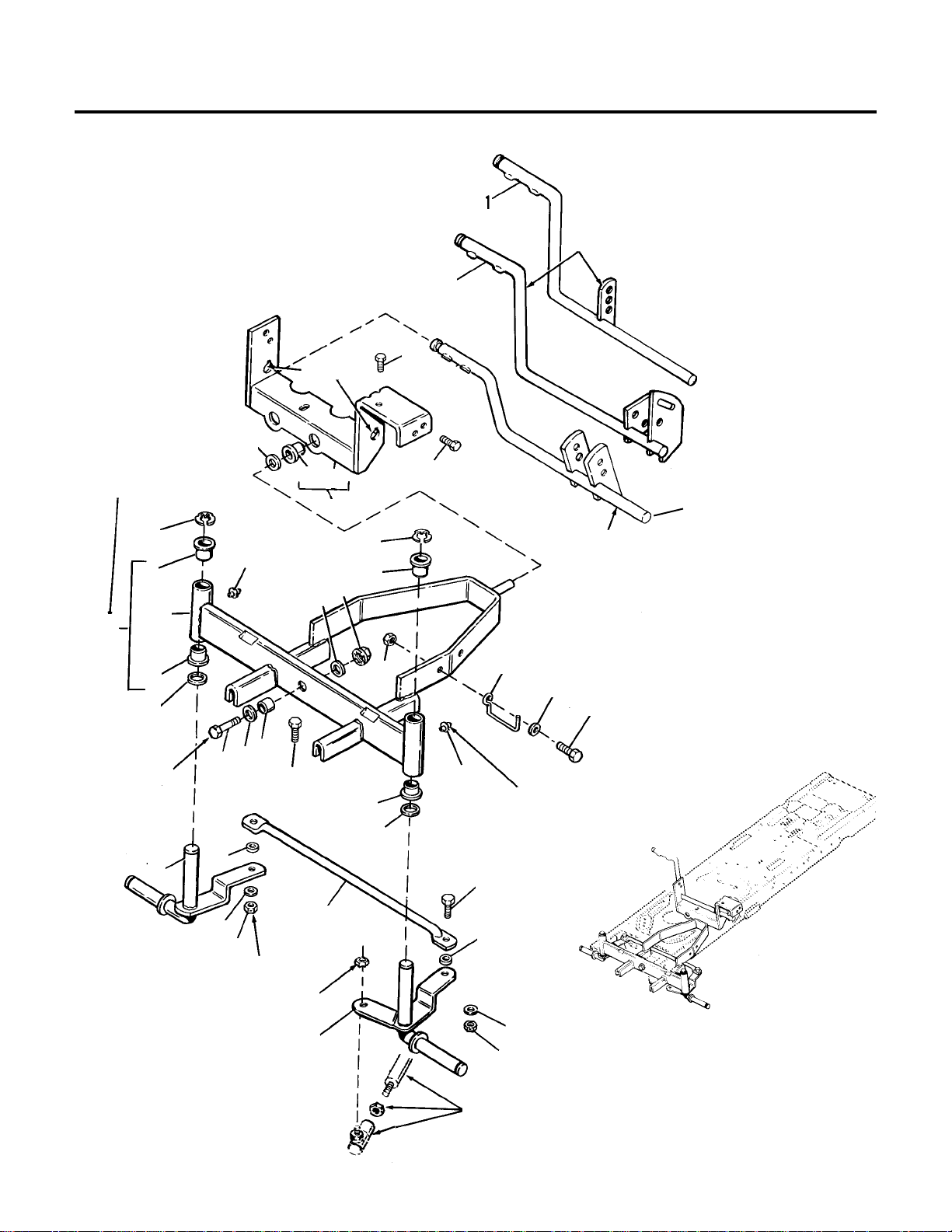
4
Front Axle
16
17
11
8
3
28
18
23
4
8
3
3
27
22
23
14
20
3
27
25
24
9
6
5
4
20
6
24
25
15
13
19
21
7
2
11
10
26
1
12
Ref. No. 7 includes
Ref. Nos. 2 & 3
Torque to
45-62 ft. lbs.
Lube spindle thru fittings
with grease (2 places)
Gear Models
See Steering &
Front Wheel Group
Torque to 15-25 ft. lbs.
Grease
Hydro Models
See Steering &
Front Wheel Group
**1513
Page 7

1 1 SUPPORT ASSY., Axle, Rear (See Ref. No. 12)
2 1 AXLE SUB ASSY. (See Ref. No. 7)
3 176440 4 BUSHING
4 921133 2 FITTING, Lube, Drive Type
5 1611703 1 SPINDLE ASSY., RH
6 1611705 2 SPACER
7 1611708 1 AXLE ASSY., Front (Incl. Ref. Nos. 2 & 3)
8 1611710 2 KLIPRING, Ext., 3/4
9 1611715 1 TIE ROD ASSY.
10 1663114 1 BUSHING
11 1664847 5 SCREW, Taptite, 5/16-18 x 3/4
12 1665601 1 SUPPORT ASSY., Rear (Incl. Ref. No. 10)
13 1668147 1 GUIDE, Drag Link
14 1671260 1 SPACER
15 1705918 1 SPINDLE ASSY., LH
16 1709305 1 LEVER ASSY., Brake (Gear models)
17 1709785 1 LEVER ASSY., Brake (Hydro models)
18 1917372 1 NUT, Hex, 5/16-18
19 1919326 1 WASHER
20 1921210 2 CAPSCREW, 3/8-16 x 1
21 1921333 1 CAPSCREW, Hex Hd., 5/16-18 x 1
22 1921525 1 CAPSCREW, Hex, 1/2-13 x 1-3/4 (Gr. 8)
23 1924361 2 WASHER
24 1924940 2 WASHER, 3/8
25 1930651 2 LOCKNUT, Hex, 3/8-16
26 1960020 1 WASHER
27 1960114 2 WASHER
28 1960362 1 LOCKNUT, Hex, Flange Lock, 1/2-13
5
REF. PART
NO. NO. QTY. DESCRIPTION
All Models
Front Axle
Page 8
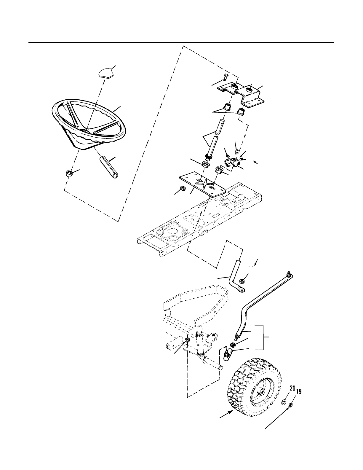
6
Steering
NOTE: Unless noted otherwise,
use the standard hardware
torque specification chart. See
the Table of Contents.
**51
13
9
2
19
18
3
6
7
12
11
17
1
2
10
2
15
4
5
16
8
2
16
Coat gear
teeth with grease.
Torque to
13-19 ft. lbs.
Torque to
17-23 ft. lbs.
See Front Wheels & Tires
for assy. parts &
mounting hardware
Torque to 50-55 ft. lbs.
NOTE NO. 1
loosen jam nut (Ref. No. 14)
and index drag link (Ref. No. 1)
to correct angle; torque jam nut
to 13 ft. lbs.
14
Page 9

1 1 LINK, Drag (Not Serviced Separately. See Ref. No. 14)
2 176440 5 BUSHING
3 1652743 1 BASE PLATE, Steering
4 1667513 1 TOP PLATE, Steering
5 1667622 1 KEY
6 1668927 1 LOCKNUT, Center, 3/8-24
7 1674076 1 ROD, Steering
8 1675388 1 GEAR, Steering
9 1686651 1 STEERING WHEEL, 13-1/2" (Incl. Ref. Nos. 13 & 19)
10 1701266 1 SHAFT ASSY., Steering
11 1705437 1 BALL JOINT ASSY., 1/2-20 Thrd. Stud.
12 1705914 1 LINK ASSY., Drag (Incl. Ref. Nos. 1, 13 & 16)
13 1714097 1 CAP, Steering Wheel
14 1919262 1 NUT, Jam, 1/2-20
15 1921332 4 CAPSCREW, 5/16-18 x 3/4
16 1928721 2 SETSCREW, 5/16-18 x 1/2
17 1930245 1 LOCKNUT, Center, 1/2-20
18 1935048 4 LOCKNUT, Flange, Whiz, 5/16-18
19 1960540 1 PIN, Spring, 5/16 x 2
7
REF. PART
NO. NO. QTY. DESCRIPTION
All Models
Steering
Page 10
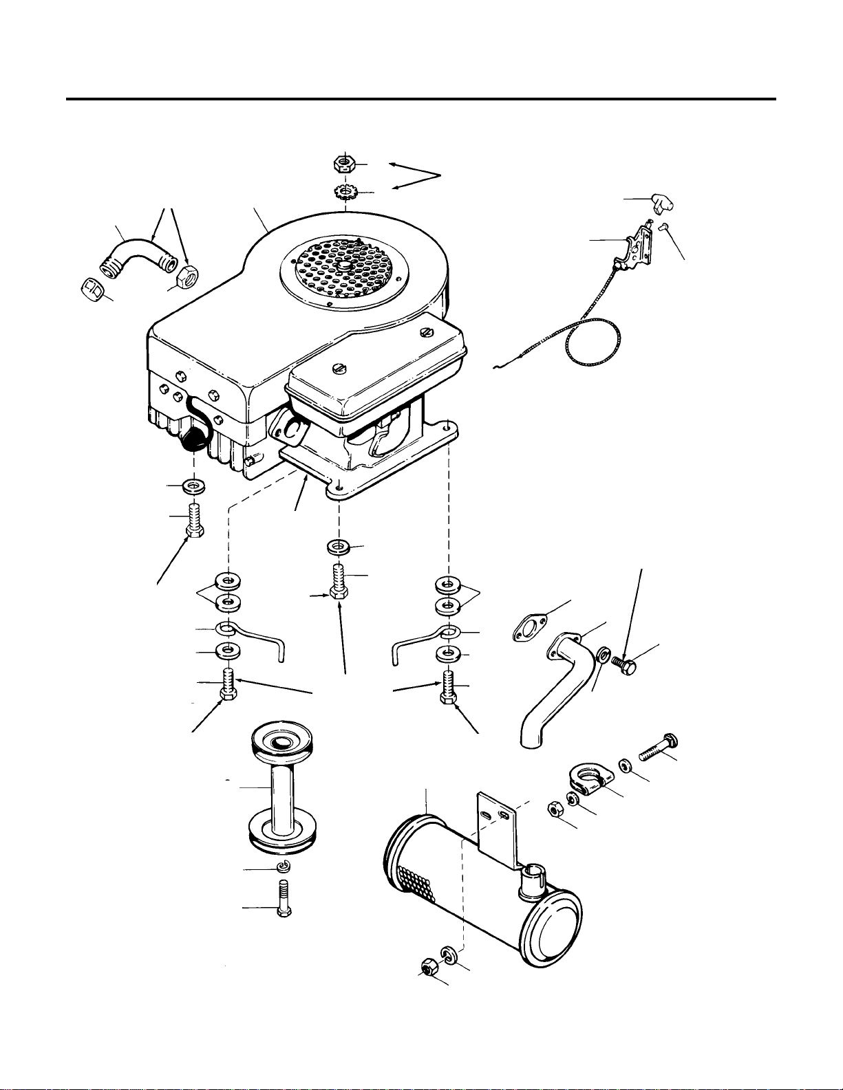
8
Engine
NOTE: Unless noted otherwise,
use the standard hardware
torque specification chart. See
the Table of Contents.
**271
Apply sealant to
threads. Locknut to
engine.
8
1
28
4
15
16
5
27
12
22
25
22
23
1 1, 13
19
24
18
17
18
17
14
20
26
17
21
10
7
22
25
22
25
23
2, 3
9
6, 25
2, 3
RH Rear on
Gear Models
(Zinc pltd. for
grounding); RH
Front on Hydro
Models.
RH Rear on
Gear Models
(Zinc pltd. for
grounding);
RH Front on
Hydro Models.
RH Front on
Gear Models;
RH Rear on
Hydro Models.
Torque to 7-11 ft. lbs. (2 places)
Coat with grease before assembly
LH Rear
Torque to
20-30 ft. lbs.
(4 places).
LH Front
Apply antiseize lubricant
to crankshaft.
Page 11

1 * 1 ENGINE, 12.5 HP
2 158499 2 STOP, Belt (Hydro models)
3 172844 2 STOP, Belt (Gear models)
4 920427 1 LOCKWASHER, Ext., 3/8, Zinc Pltd.
5 960241 2 RIVET, Pop, 1/4
6 960361 1 SCREW, Taptite, 3/8-16 x 2, Zinc Pltd. (Gear models)
7 1650670 1 GASKET, Muffler
8 1655405 1 PIPE, Oil Drain
9 1655848 1 MUFFLER
10 1655860 1 PIPE, Exhaust
11 1657118 1 PULLEY ASSY., Engine (Hydro models)
12 1667346 1 CAP, Pipe
13 1674163 1 PULLEY ASSY., Engine (Gear models)
14 1676183 1 CLAMP
15 1707388 1 CONTROL ASSY., Throttle
16 1713846 1 KNOB, Throttle
17 1917356 5 LOCKWASHER, 5/16
18 1917372 3 NUT, Hex, 5/16-18
19 1918199 1 LOCKWASHER, 7/16
20 1919326 1 WASHER
21 1921332 2 SCREW, Whizlock, 5/16-18 x 3/4
22 1924356 6 WASHER, Plain, 3/8
23 1924940 2 WASHER, 13/32
24 1928038 1 CAPSCREW, Hex, 7/16-20 x 1-1/4
25 1930598 3 SCREW, Taptite, 3/8-16 x 1-1/2
26 1931342 1 BOLT, Carriage, 5/16-18 x 2-3/4 Gr. 5
27 1932849 1 LOCKNUT
28 1960251 1 NUT, Hex Jam Lock, 3/8-16
* See your local Briggs & Stratton dealer for service parts.
NOTE: Use Simplicity engine oil as follows (check inside front cover for part number):
• SAE 30W SG/CC for temperature operating range of 32O F. and above.
• 5W30 SF/CD for temperature operating range of below 32O F.
9
REF. PART
NO. NO. QTY. DESCRIPTION
All Models
Engine
Page 12
10
NOTE: Unless
noted otherwise,
use the standard
hardware torque
specification chart.
See the Table of
Contents.
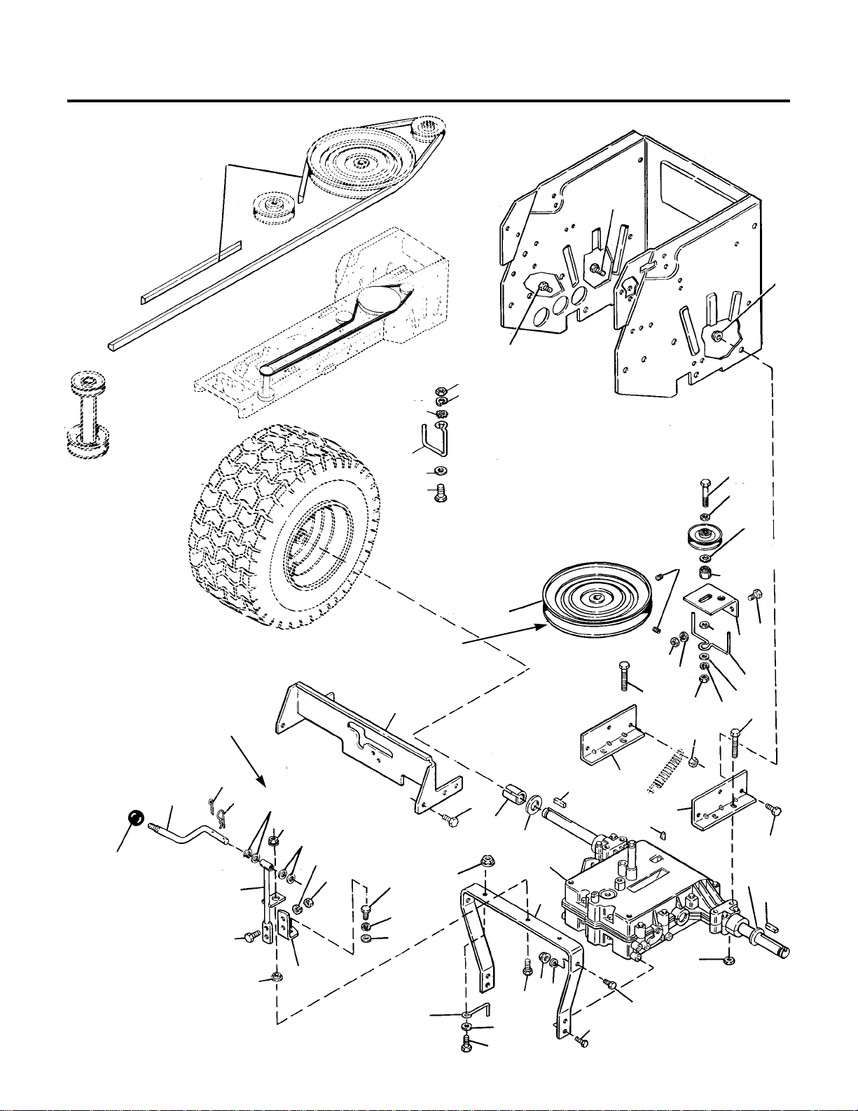
**2370
Gear Transaxle
16
31
24
30
9
28
33
41
35
37
42
15, 39
Attach to inside
of rear wrapper
31
18
37
17
37
23
21
23
21
34
8
34
44
6
6
49
4
47
12
46
27
26
20
19
14
45
46
24
25
36
22
2
32
7
13
33
40
41
5
31
48
49
38
31
3
1
21
33
28
31
43
Lubricate every
25 hours.
Use washers as req'd to
adjust shift lever to
neutral slot.
.25 ± .03 clearance
between pulley hub &
snap ring on trans.
Slide each bracket
(Ref. No. 6) towards
center of transaxle.
Torque to
14-21 ft. lbs.
Apply anti-seize lubricant to axles before
assembling wheels.
Torque to 11-17 ft. lbs.
(4 places).
10
23
Page 13

1 * 1 TRANSAXLE, 5 Speed, Peerless Model 930-039
2 158499 2 BELT STOP
3 905123 1 KEY, Woodruff, #9
4 1663180 1 SPACER
5 1666631 1 SUPPORT, Transmission, Front
6 1666632 2 SUPPORT, Transmission, Rear
7 1666638 1 LINK, Shift, Lower
8 1666693 1 PULLEY ASSY., Transmission
9 1666709 1 STOP, Belt
10 1676375 1 SPACER
12 1701555 1 QUADRANT, Shift
13 1705590 1 SPACER, Special
14 1708022 1 SHIFT LINK ASSY., Upper
15 1708029 1 PULLEY, Idler, "V"
16 1708114 1 “V” BELT
17 1708221 1 BELT STOP
18 1709864 1 BRACKET, Pulley
19 1713843 1 KNOB, Ball, Shift
20 1713850 1 ROD, Shift
21 1916950 5 NUT, Hex, 3/8-16
22 1916964 1 LOCKWASHER, 1/4
23 1916965 3 LOCKWASHER, 3/8
24 1917356 3 LOCKWASHER, 5/16
25 1917372 3 NUT, Hex, 5/16-18
26 1918196 1 PIN, Quick
27 1918447 1 PIN, Cotter
28 1919326 3 WASHER, 11/32
29 1920415 1 CAPSCREW, Hex, 3/8-16 x 1-1/4
30 1920427 1 LOCKWASHER, Ext.
31 1921210 9 CAPSCREW, Hex 3/8-16 x 1
32 1921319 1 WASHER, Plain
33 1921333 4 CAPSCREW, Hex, 5/16-18 x 1
34 1921719 4 CAPSCREW, Hex, 5/16-18 x 2-1/2
35 1921973 1 CAPSCREW, 3/8-16 x 2-3/4
36 1922234 1 CAPSCREW, Hex, 1/4-28 x 5/8
37 1922755 3 WASHER
38 1923362 4 LOCKNUT, 5/16-18
39 1924940 1 WASHER, 13/32
40 1925003 6 SCREW, Taptite, 1/4-20 x 3/8
41 1928352 6 LOCKNUT, Hex, Flange, 3/8-16
42 1930540 2 SETSCREW, 5/16-18 x 5/8
43 1930601 2 SCREW, Taptite, 5/16-18 x 5/8
44 1930651 1 LOCKNUT, Hex, 3/8-16
45 1935048 1 NUT, Hex, Flange Hd., 5/16-18
46 1960027 4 WASHER, Rev. Pinion
47 1960160 A/R WASHER
48 1960202 1 WASHER, 1/4
49 8221042 2 KEY, 3/16 x 3/16 x 1-1/2
* See your local Tecumseh/Peerless distributor for service parts. See Table of Contents for service
parts listing.
11
REF. PART
NO. NO. QTY. DESCRIPTION
Mfg. Nos. 1692401, 1692405, 1692409, 1692493
Gear Transaxle
Page 14
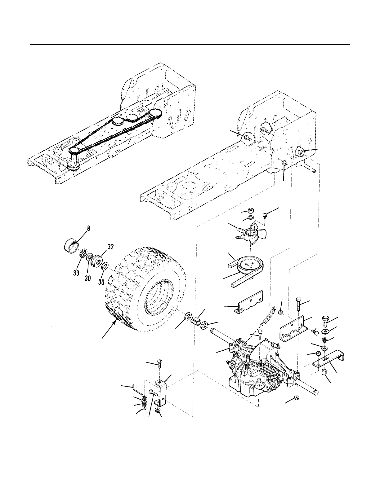
12
Hydro Transaxle - Group 1
NOTE: Unless noted otherwise,
use the standard hardware
torque specification chart. See
the Table of Contents.
**2566
20
26
29
30
16
8
2
27
21
5
19
23
24
9
12
30
32
31
1
10
5
22
6
4
7
11
28
4
3
17
14
15
20
28
13
See Rear Wheels & Tires
for assy. parts &
mounting hardware
Page 15

1 157127 1 SPRING, Conical
2 170164 1 V-BELT
3 172844 1 BELT STOP
4 960202 8 WASHER, Plain, 3/4 x 1-5/8 x 1/8
5 1666632 2 SUPPORT, Transmission, Rear
6 1667191 2 SPACER
7 1686613* 1 TRANSMISSION, Hydro
Hydro Gear Model 318-0500
8 1707933 1 FAN
9 1709271 1 LEVER, Tow Valve
10 1709786 1 PULLEY ASSY.
11 1709790 1 STRAP, Torque
12 1709901 1 SPACER
13 1916966 1 LOCKWASHER, 1/2
14 1917356 1 LOCKWASHER, 5/16
15 1917372 1 NUT, Hex, 5/16-18
16 1919262 1 NUT, Hex, Jam, 1/2-20
17 1919381 1 WASHER, 11/32 X 1 X 3/16
18 1920415 1 CAPSCREW, Hex Hd., 3/8-16 x 1-1/4
19 1921210 3 CAPSCREW, Hex Hd., 3/8-16 x 1
20 1921332 1 CAPSCREW, Hex Hd., 5/16-18 x 3/4
21 1921719 4 CAPSCREW, Hex Hd., 5/16-18 x 2-1/2
22 1921977 1 CAPSCREW, Hex Hd., 5/16-18 x 1-1/4
23 1922611 1 WASHER, Plain
24 1923358 1 NUT, Hex, Full Lock, 1/4-20
25 1928352 4 LOCKNUT, Hex, Flange, 3/8-16
26 1930645 1 NUT, Hex, Flange, 3/8
27 1930651 1 LOCKNUT, Hex, 3/8-16
28 1931277 1 NUT, Hex, Whiz Lock, 5/16-18
29 1931335 1 CARRIAGE BOLT, 5/16-18 x 1
30 1933958 3 SCREW, Taptite, 1/4-20 x 1-1/64
31 1935048 4 NUT, Hex, Flange Lock, 5/8-18
32 1960151 1 WASHER, Plain, 1/4 x 1-11/32 x 1/16
33 1960509 1 SCREW, Taptite, Hex Hd., 10-24 x 1-1/4
* See pages 52 - 53 for service parts.
13
REF. PART
NO. NO. QTY. DESCRIPTION
Mfg. Nos. 1692403, 1692407, 1692412, 1692495
Hydro Transaxle - Group 1
Page 16
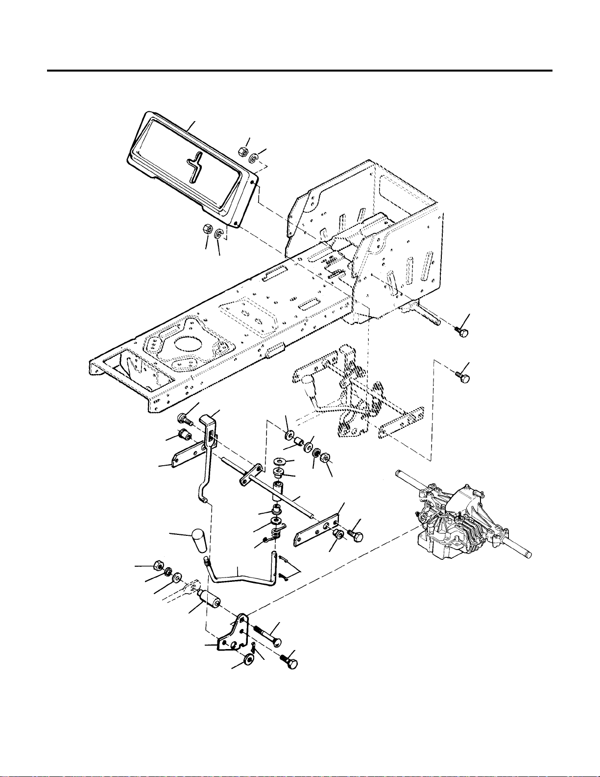
14
Hydro Transaxle - Group 2
NOTE: Unless noted otherwise,
use the standard hardware
torque specification chart. See
the Table of Contents.
**2567
10
13
12
13
12
21
19
16
8
22
15
24
12
21
5
21
2
14
2
18
2
7
1
3
6
23
17
14
20
9
4
15
12
13
11
5
2
Page 17

1 1666697 1 SPACER
2 1704428 4 BUSHING
3 1707424 1 SPRING, Torsion
4 1709227 1 SPACER
5 1709775 2 BRACE, Shift Panel
6 1709776 1 ROD, Shift
7 1709777 1 SHIFT ROD ASSY.
8 1709782 1 ROD, Control
9 1709784 1 CONTROL LEVER
10 1709824 1 PANEL, Shift
11 1713843 1 KNOB, Large
12 1917356 3 LOCKWASHER, Spring, 5/16
13 1917372 3 NUT, Hex, 5/16-18
14 1918447 3 COTTER PIN, 15/16 X 3/4
15 1919326 4 WASHER, Plain, 11/32 x 3/4 x 1/16
16 1919381 1 WASHER, 11/32 x 1 x 1/8
17 1921333 1 CAPSCREW, Hex Hd., 5/16-18 x 1
18 1924361 1 WASHER, Plain, 1/2 x 1-1/4 x 5/64
19 1924856 4 SCREW, Taptite, 1/4-20 x 1/2
20 1924940 1 WASHER, Plain, 13/32 x 7/8 x 5/64
21 1925003 4 SCREW, Taptite, 5/16-18 x 1/2
22 1931335 1 CARRIAGE BOLT, 5/16-18 x 1
23 1931337 1 CARRIAGE BOLT, 5/16-18 x 1-1/2
24 1960170 1 WASHER, Plain, 1/2 x 1 x 3/32
15
REF. PART
NO. NO. QTY. DESCRIPTION
Mfg. Nos. 1692403, 1692407, 1692412, 1692495
Hydro Transaxle - Group 2
Page 18
16
Brake & Clutch - Gear Models
NOTE: Unless noted otherwise,
use the standard hardware
torque specification chart. See
the Table of Contents.
**50
Between frame & head
of stud (Ref. No. 2)
21
20
2
22
23
25
26
4
14
22
23
10
28
19
18
13
27
15
12
32
30
1
9
31
16
24
11
17
7
24
3
Idler Assy. must pivot
freely with .015" maximum end play.
Clutch Rod
Grease
Grease
Brake Rod
A minimum of two full
threads must extend thru nut
after assembly
8
5
6
29
Install in uper
hole on clutch
pedal assy. arm.
Install in lower
brake cam lever
hole.
Grease pedal shaft
and insert damper
(Ref. No. 8) into pedal
groove before assembling
pedal (Ref. No 5).
Small end of spring
Spring
(Ref. No. 12) in frame
Page 19

1 157041 1 SPRING, Compression
2 157273 1 STUD
3 159106 1 SPRING, Tension
4 1653076 1 IDLER ASSY.
5 1656852 1 PEDAL, Foot
6 1656854 1 PLATE, End
7 1657222 1 GUIDE ASSY., Rod
8 1659907 1 DAMPER, Rubber
9 1663138 1 GUIDE, Rod
10 1666294 1 SPACER
11 1666656 1 ROD, Brake
12 1666759 1 SPRING, Return
13 1677135 1 GUARD, Spring
14 1685150 1 PULLEY ASSY. (Incl. Ref. No. 10)
15 1702156 1 ROD, Clutch
16 1708226 1 SPRING
17 1708228 1 SPACER
18 1916950 1 NUT, Hex, 3/8-16
19 1916965 1 LOCKWASHER, 3/8
20 1918199 1 LOCKWASHER, 7/16
21 1918213 1 NUT, Hex, 7/16-14
22 1918447 2 PIN, Cotter
23 1919326 2 WASHER, 11/32
24 1919438 2 LOCKNUT, 5/16-18
25 1921969 1 CAPSCREW, 3/8-16 x 1-1/2
26 1922755 1 WASHER, Plain
27 1924058 1 LOCKNUT, Hex, 7/16-14
28 1924940 1 WASHER, Plain, 5/16
29 1927429 2 SCREW, Taptite, 1/4-20 x 5/8
30 1928804 1 SETSCREW, 1/4-20 x 3/8
31 1935048 1 LOCKNUT, Hex, Flange, 5/16-18
32 8191022 1 COLLAR, Set
17
REF. PART
NO. NO. QTY. DESCRIPTION
Mfg. Nos. 1692401, 1692405, 1692409, 1692493
Brake & Clutch - Gear Models
Page 20

18
Brake & Clutch - Hydro Models
NOTE: Unless noted otherwise,
use the standard hardware
torque specification chart. See
the Table of Contents.
**2568
18
20
2
12
10
13
1
24
19
21
9
14
16
17
22
23
27
29
29
11
15
26
7
26
28
25
26
19
21
5
4
3
26
28
4
Transmission
Brake Arm
Apply anti-seize lubricant to
Ref. No. 5 before assy.
8
Hook in center slot rear of steering sump
6
Lubricate bushings (Ref.
No. 4) with grease.
Page 21

1 156302 1 SPRING, External
2 159106 1 SPRING, External
3 1666759 1 SPRING
4 1663114 2 BUSHING, Plastic
5 1674669 2 SPACER
6 1707289 1 PULLEY, Idler
7 1708029 1 PULLEY, "V"
8 1709097 1 SPRING
9 1709780 1 ROD, Clutch
10 1709783 1 ROD, Return
11 1709789 1 IDLER ARM ASSY.
12 1709791 1 ROD, Brake
13 1709793 1 BRAKE ARM ASSY.
14 1709810 1 ACTUATOR, Switch
15 1709863 1 BELT STOP
16 1917356 3 LOCKWASHER, Spring, 3/8
17 1917372 3 NUT, Hex, 3/8-16
18 1918447 2 COTTER PIN, 3/32 x 3/4
19 1918447 2 COTTER PIN, 3/32 x 3/4
20 1919326 2 WASHER, Plain, 11/32 x 3/4 x 1/16
21 1919326 2 WASHER, Plain, 11/32 x 3/4 x 1/16
22 1919438 1 NUT, Hex, Esna, Lock, 3/8-16
23 1919439 1 NUT, Hex, Esna, Lock, 3/8-16
24 1921332 1 CAPSCREW, Hex Hd., 5/16-18 x 3/4
25 1923903 1 CAPSCREW, Hex Hd., 3/8-16 x 3
26 1924940 7 WASHER, 13/32 X 7/8 X 5/64
27 1928352 3 NUT, Flange, Whizlock, 3/8-16
28 1928352 3 NUT, Flange, Whizlock, 3/8-16
29 1931353 2 CARRIAGE BOLT, 3/8-16 x 1-3/4
Brake Linkage Adjustment
1. Perform parking brake adjustment in Operator’s Manual.
2. With brake/clutch pedal depressed and parking brake licked, adjust brake spring (Ref. No. 8) to have an
overall length of 2-7/8"- 3".
19
REF. PART
NO. NO. QTY. DESCRIPTION
Mfg. Nos. 1692403, 1692407, 1692412, 1692495
Brake & Clutch - Hydro Models
Page 22

20
Electrical - Gear Models
NOTE: Unless
noted otherwise,
use the standard
hardware torque
specification
chart. See the
Table of Contents.
**2413
14
31
10
20
27
28
13
18
22
34
17
35
3
35
23
16
34
9
8
16
2
26
24
25
17
6
4
11
5
1
29
30
29
7
19
21
33
12
Slide boot over terminal after securing to
battery.
Place end of
hose through
hole in frame.
Mount in
frame
To Operator
Present Seat Switch
Zinc. Pltd.
To Neutral Start
Switch
To PTO Switch
Engine ground
To Alternator
Mounts to
lower RH hood
hinge away from
pivot pinch point
and muffler
To Magneto.
Tie wrap wires
together using
Ref. No. 6
To Starter
Motor
Zinc Pltd.
NOTE: Apply
grease to ignition
switch terminals
(Ref. No. 14) and
wire harness plug
before connecting.
32
30
36
Page 23

1 122023 1 COVER, Terminal
2 122184 1 SWITCH, Headlight
3 165073 1 CLIP
4 172434 1 CLIP, Cable
5 930222 1 CLIP, Wire
6 932747 1 TIE, Self-Locking
7 1603618 1 CABLE, Ground
8 1665237 1 WIRE ASSY.
9 1665238 1 CIRCUIT BREAKER
10 1669831 1 HOLD DOWN, Battery
11 1674358 1 WIRE ASSY., Headlights
12 1677296 1 BOOT, Insulator
13 1685215 1 BATTERY
14 1700472 2 ROD, Battery Hold Down
15 1685290 1 SOLENOID
16 1701522 1 CABLE
17 1701580 2 SWITCH, PTO and Neutral
18 1703484 1 CABLE, Ground
19 1704349 2 NUT, Retainer, 1/4-20
20 1704581 1 VENT CAP, Battery
21 1704583 1 HOSE, Drain
22 1707755 1 MODULE, DSI Interlock, Seat Switch
23 1707757 1 HARNESS, Wiring
24 1686637 1 SWITCH (Incl. Ref. Nos. 26, 27 & 36)
25 1714054 1 KEY SET (2 keys)
26 1714055 1 ADAPTER, Nut
27 1916622 2 NUT, Hex, 1/4-20
28 1916964 2 LOCKWASHER, 1/4
29 1917356 2 LOCKWASHER, 5/16
30 1920263 2 NUT, Hex, 5/16-24
31 1921319 2 WASHER, 9/32
32 1921319 2 WASHER, 1/4 I.D.
33 1923341 2 CAPSCREW, Hex Hd., 1/4-20 x 3/4
34 1927429 2 SCREW, Taptite, 1/4-20 x 5/8, Zinc Pltd.
35 1929477 4 SCREW, Taptite, #10-24 x 1/2
36 1960547 1 LOCKWASHER, Internal Tooth, 5/8 (Thin)
21
REF. PART
NO. NO. QTY. DESCRIPTION
Mfg. Nos. 1692401, 1692405, 1692409, 1692493
Electrical - Gear Models
Page 24

22
Electrical - Hydro Models
9
15
32
19
22
12
29
28
30
6
33
32
21
11
**2412
NOTE: Unless
noted otherwise,
use the standard
hardware torque
specification
chart.
Place end of
hose thru
hole in
frame.
31
23
18
20
25
10
5
17
35
24
4
3
26
27
2
13
34
16
30
31
7
1
8
Apply grease to ignition
switch terminals (Ref.
No. 14) and wire harness plug before connecting.
Zinc Pltd.
To Neutral
Start Switch
To Alternator
Engine ground
Mounts to lower
R.H. hood hinge
away from pivot
pinch point and
muffler.
To Magneto
To
Starter
Motor
Tie wrap wires
together using
Ref. No. 5.
Mount in
frame.
To Operator
Present Seat
Switch.
Slide boot over terminal after securing
to battery.
Maximum torque
of 22 in.-lbs.
Ground
34
14
36
Page 25

1 122023 1 COVER, Terminal
2 122184 1 SWITCH, Headlight
3 165073 1 CLIP, Wire
4 172434 1 CLIP, Wire
5 932747 1 TIE, Cable (Qty. 3 used on hydro models)
6 1603618 1 CABLE (Positive)
7 1665237 1 WIRE ASSY.
8 1665238 1 CIRCUIT BREAKER
9 1669831 1 HOLD DOWN, Battery
10 1674358 1 WIRE ASSY., Headlights
11 1677296 1 BOOT, Insulator
12 1685215 1 BATTERY
13 1685290 1 SOLENOID
14 1686637 1 SWITCH, Ignition (Incl. Ref. Nos. 26, 27 & 36)
15 1700472 2 ROD, Battery Hold Down
16 1701522 1 CABLE
17 1701580 1 SWITCH, PTO
18 1703484 1 CABLE, Ground (Negative)
19 1704349 2 NUT, Retainer, 1/4-20
20 1704379 1 SWITCH, Transmission Interlock
21 1704581 1 VENT CAP, Battery
22 1704583 1 HOSE, Battery Drain
23 1707755 1 MODULE, Interlock, Seat Switch
24 1707757 1 HARNESS, Wiring
25 1709849 1 ADAPTOR, Wire
26 1714054 1 KEY SET ( 2 keys)
27 1714055 1 ADAPTOR NUT
28 1916622 2 NUT, Hex, 1/4-20
29 1916964 2 LOCKWASHER, 1/4
30 1917356 2 LOCKWASHER, 5/16
31 1920263 2 NUT, Hex, 5/16-24
32 1921319 4 WASHER, 1/4
33 1923341 2 CAPSCREW, Hex Hd., 1/4-20 x 3/4
34 1927429 2 SCREW, Taptite, 1/4-20 x 5/8, Zinc Pltd.
35 1929477 2 SCREW, Taptite, #10-24 x 1/2
36 1960547 1 LOCKWASHER, Internal Tooth, 5/8 (Thin)
23
REF. PART
NO. NO. QTY. DESCRIPTION
Mfg. Nos. 1692403, 1692407, 1692412, 1692495
Electrical - Hydro Models
Page 26

24
Hood, Grille, Dash & Fuel Tank
NOTE: Unless noted otherwise,
use the standard hardware
torque specification chart. See
the Table of Contents.
**2424
2
27
45
37
36
12
18
15
35
24
17
13
14
26
29
33
44
33
32
34
28
22
38
19
21
20
3
43
10
42
41
9
7
42
39
1
23
6
8
44
11
16
44
30
25
Torque to
20-30 in. lbs.
31
5
Torque to
20-30 in lbs.
(4 places)
40
4
31
Brace (Ref.
No. 6) must
be assembled
parallel to this
surface.
Page 27

1 1 FUEL TANK (See Ref. No. 11)
2 171252 1 CAP, Fuel Tank
3 173206 1 FILTER, Fuel
4 1654930 1 BUSHING
5 1664897 1 WASHER, Foam
6 1665301 1 BRACE
7 1666447 1 FITTING
8 1676861 1 HOSE, Fuel (Cut to 12" long)
9 1667248 4 CLIP, Canoe
10 1672123 2 EDGING, Lower Dash
11 1685297 1 TANK ASSY., Fuel
(Incl. Ref. Nos. 1, 4, 7, 8 & qty. 1 of 44)
12 1677370 2 SOCKET, Bulb, Headlight
13 1677371 2 BULB, Headlight, 12.8V
14 1703248 1 LENS, Headlight
15 1703249 1 BEZEL, Headlight
16 1703292 1 GRILLE
17 1703945 1 HEADLIGHT ASSY. (Incl. Ref. Nos. 13, 14, 15, 16 & 19)
18 1703946 2 HEAT SHIELD, Headlight
19 1704626 2 SPACER, Hood
20 1704628 2 CLIP, Hairpin
21 1705248 2 PIVOT, Hood
22 1705249 2 SPACER
23 1707393 1 DASHBOARD, Bottom
24 1708750 1 HOOD, Orange
41708750 1 HOOD, Red
25 1708751 1 SIDE PANEL, LH, Orange
41708751 1 SIDE PANEL, LH, Red
26 1708752 1 SIDE PANEL, RH, Orange
41708752 1 SIDE PANEL, RH, Red
27 1708753 1 DASHBOARD, Top
28 1708754 1 HINGE, LH
29 1708755 1 HINGE, RH
30 1708756 1 BAR-TIE, Hood
31 1713337 5 PAD
32 1917356 2 LOCKWASHER, 5/16
33 1917372 2 NUT, Hex, 5/16-18
34 1919326 2 WASHER, Plain 5/16
35 1920397 12 NUT, Hex, Nylon-lock, 1/4 -20
36 1921319 8 WASHER, 1/4,std.
37 1921961 2 CAPSCREW, Hex, 1/4-20 x 1-1/4
38 1921977 2 CAPSCREW, Hex Hd., 5/16-18 x 1-1/4
39 1923358 2 LOCKNUT, Hex, 1/4-20
40 1925592 2 SCREW, Taptite, 1/4-20 x 3/4
41 1929783 4 SCREW, Taptite, 1/4-20 x 1
42 1931704 6 LOCKWASHER, Dish, 1/4
43 1960112 2 CLAMP, Hose
44 1960295 12 SCREW, Hex, Whizlock, 1/4 -20 x 5/8
45 1960498 2 SCREW, Hex , Washer Hd., 1/4-20 x 5/8
25
REF. PART
NO. NO. QTY. DESCRIPTION
All Models
Hood, Grille, Dash & Fuel Tank
Page 28

26
Seat & Deck
NOTE: Unless noted otherwise, use the standard hardware torque specification
chart. See the Table of
Contents.
**1307
15
17
21
18
1
1
8
24
29
5
30
7
19
20
27
23
9
14
28
27
11
27
22
23
10
25
28
13
4
12
3
2
16
18
Hydro Models
29
Seat supports must
pivot freely when
assembled
21
21
23
26
6
23
Gear Models
Page 29

1 930222 2 CLIP
2 1666690 2 SPRING, Seat
3 1666691 2 COVER, Wire
4 1668839 1 PANEL, Shift (Gear models)
5 1678415 2 HINGE, Lower
6 1701229 1 BUSHING, Snap
7 1701252 2 SEAT LATCH ASSY.
8 1701560 2 HINGE, Upper
9 1701736 1 SUPPORT, Seat, RH
10 1701737 1 SUPPORT, Seat, LH
11 1701742 2 BUMPER, Plug
12 1702690 1 DECK, Seat, Orange
41702690 1 DECK, Seat, Red
13 1709775 2 BRACE, Shift Panel (Hydro models)
14 1709824 1 PANEL, Shift (Hydro models)
15 1713839 1 SEAT (Incl. Ref. No. 17)
16 1714320 1 SWITCH, Seat
17 1714482 1 SEAT COVER
18 1714494 1 PUSH NUT, 27/64
19 1917356 2 LOCKWASHER, 5/16
20 1917372 2 NUT, Hex, Full, 5/16-18
21 1919326 4 WASHER, Plain, 5/16
22 1919438 2 LOCKNUT, Hex, 5/16-18
23 1921332 10 CAPSCREW, Hex, 5/16-18 x 3/4
24 1923701 2 CAPSCREW, Hex, 3/8-16 x 2
25 1924856 4 SCREW, Taptite, 1/4-20 x 3/8 (Hydro models)
26 1925205 4 CAPSCREW, Hex Hd., 5/16-18
27 1927557 8 NUT, Hex, Flange, Whizlock, 5/16-18
28 1928729 2 SCREW, Hex, Taptite, 5/16-18 x 3/8 (Gear models)
29 1930651 2 LOCKNUT, Hex, 3/8-16
30 1931333 2 CARRIAGE BOLT, 5/16-18 x 3/4
27
REF. PART
NO. NO. QTY. DESCRIPTION
All Models
Seat & Deck
Page 30

28
Front Wheels & Tires
NOTE: Unless noted otherwise,
use the standard hardware
torque specification chart. See
the Table of Contents.
Grease front
wheel assemblies.
10
9
9
7
2
8
1
5
11
6
3
4
Page 31

1 172353 2 VALVE STEM & CAP
2 912808 2 FITTING, Grease
3 960202 2 WASHER, 3/4
4 1611710 2 KLIP RING, 3/4
5 1664090 2 TUBE, Front Wheel, 4.10/3.50-6
6 1673333 2 HUB CAP (AGCO & Massey Ferguson models only)
7 1709856 2 FRONT WHEEL & TIRE ASSY., Metallic Gray, 15 x 6.00-6
(Incl. Ref.Nos. 1, 8 & 10)
8 1713166 2 TIRE, Front Wheel, 15 x 6.00-6
9 1713167 4 BEARING
10 1713168 2 FRONT WHEEL ASSY., Metallic Gray,
(Incl. Ref. Nos. 2 & 9)
11 1714428 2 HUB CAP, 6" (Simplicity models only)
29
REF. PART
NO. NO. QTY. DESCRIPTION
All Models
Front Wheels & Tires
Page 32

30
Rear Wheels & Tires
NOTE: Unless noted otherwise,
use the standard hardware
torque specification chart. See
the Table of Contents.
5
6
7
1
9
3
4
9
2
8
Qty. 1 or 2
(As required left
wheel only)
Page 33

1 172353 2 VALVE STEM & CAP
2 927794 2 E-RING
3 1676519 2 HUB CAP (AGCO & Massey Ferguson models)
4 1701435 2 RETAINER, Hub Cap (AGCO & Massey Ferguson models)
5 1709857 2 REAR WHEEL & TIRE ASSY., Metallic Gray, 18 x 8.50-8 (Incl. Ref.
Nos. 1, 5 & 6)
6 1713170 2 TIRE, Rear Wheel, 18 x 8.50-8
7 1713171 2 REAR WHEEL ASSY., Metallic Gray, 18 x 8.50-8
8 1714429 2 HUB CAP, 8" (Simplicity models)
9 1960114 2 WASHER, 3/4 (Simplicity models)
31
REF. PART
NO. NO. QTY. DESCRIPTION
All Models
Rear Wheels & Tires
Page 34

32
Decals - Simplicity Models
NOTE: Unless noted otherwise, use the standard hardware torque specification
chart. See the Table of
Contents.
11
14
13
6
3
2
17, 18, 19
17, 18, 20
12
4
10
9
8
7
1
5
Located on LH side
of wrapper to the right
of the release lever.
Located on LH side
of wrapper above
transmission fan.
Located underneath hood
16
Page 35

1 1 DECAL, OPEI (Not Serviced)
2 1656855 1 DECAL, Mower Height
3 1668202 1 DECAL, Simplicity
4 1701270 1 DECAL, Warning, Fan (Hydro models)
5 1704276 1 DECAL, Danger, Rotating Blade
6 1702944 1 DECAL, Decibel (Export)
7 1704277 1 DECAL, Danger, Deflector in Place
8 1704910 2 DECAL, Cutting Width, 36"
9 1708277 1 DECAL, Shift Pattern (Gear models)
10 1708918 1 DECAL, Release Valve, (Hydro models)
11 1708927 1 DECAL, USA
12 1709061 1 DECAL, Touch-up Paint
13 1709371 1 DECAL, Dash, RH Side
14 1709387 1 DECAL, Dash, LH Side
15 1709861 1 DECAL, Shift Pattern (Hydro models)
16 1713550 1 DECAL, Drive Belt
17 1713966 2 DECAL, Hood, 5-Speed 12
18 1713967 1 DECAL, Hood, Regent 12.5 Hydro
19 1713968 1 DECAL, Hood, Simplicity, RH
20 1713969 1 DECAL, Hood, Simplicity, LH
33
REF. PART
NO. NO. QTY. DESCRIPTION
Simplicity Models
Decals
Page 36

34
Decals - AGCO Allis Models
NOTE: Unless noted otherwise, use the standard hardware torque specification
chart. See the Table of
Contents.
14
17
16
13
2
6
5
1
4
8, 10, 17
9, 11,16
15
3
12
7, 18
Located on LH side
of wrapper to the right
of the release lever.
Located on LH side
of wrapper above
transmission fan.
Located underneath hood
19
Page 37

1 1 DECAL, OPEI (Not Serviced)
2 1656855 1 DECAL, Mower Height
3 1701270 1 DECAL, Warning, Fan, (Hydro models)
4 1701270 1 DECAL, Danger, Rotating Blade
5 1704277 1 DECAL, Danger, Deflector in Place
6 1704910 2 DECAL, Cutting Width, 36"
7 1708276 1 DECAL, Shift Pattern (Gear models)
8 1708820 1 DECAL, Hood, 512H, AGCO ALLIS, LH
9 1708821 1 DECAL, Hood, 512H AGCO ALLIS, RH
10 1708823 1 DECAL, Hood, 512G AGCO ALLIS, LH
11 1708824 1 DECAL, Hood, 512G AGCO ALLIS, RH
12 1708918 1 DECAL, Release Valve, (Hydro models)
13 1708926 2 DECAL, AGCO Allis
14 1708927 1 DECAL, USA
15 1709061 1 DECAL, Touch-up Paint
16 1709371 1 DECAL, Dash, RH
17 1709387 1 DECAL, Dash, LH
18 1709861 1 DECAL, Shift Pattern (Hydro models)
19 1713550 1 DECAL, Drive Belt
35
REF. PART
NO. NO. QTY. DESCRIPTION
AGCO Allis Models
Decals
Page 38

36
Decals - Massey Ferguson Models
NOTE: Unless noted otherwise, use the standard hardware torque specification
chart. See the Table of
Contents.
9
11
10
14
14
2
6
5
1
4
16, 18
15, 17
3
8
7, 13
Located on LH side
of wrapper to the right
of the release lever.
Located on LH side
of wrapper above
transmission fan.
Located underneath hood
13
Page 39

1 1 DECAL, OPEI (Not Serviced)
2 1656855 1 DECAL, Mower Height
3 1701270 1 DECAL, Warning, Fan, (Hydro models)
4 1704276 1 DECAL, Danger, Rotating Blade
5 1704277 1 DECAL, Danger, Deflector in Place
6 1704910 2 DECAL, Cutting Width, 36"
7 1708277 1 DECAL, Shift Pattern (Gear models)
8 1708918 1 DECAL, Release Valve, (Hydro models)
9 1708927 1 DECAL, USA
10 1709371 1 DECAL, Dash, RH
11 1709387 1 DECAL, Dash, LH
12 1709861 1 DECAL, Shift Pattern (Hydro models)
13 1713550 1 DECAL, Drive Belt
14 1714363 2 DECAL, Massey Ferguson
15 1714368 1 DECAL, Hood, 2512G Massey Ferguson, LH
16 1714369 1 DECAL, Hood, 2512G Massey Ferguson, RH
17 1714370 1 DECAL, Hood, 2512H, Massey Ferguson, LH
18 1714371 1 DECAL, Hood, 2512H Massey Ferguson, RH
37
REF. PART
NO. NO. QTY. DESCRIPTION
Massey Ferguson Models
Decals
Page 40

38
36" Mower Deck - Deck, Arbor & Blades
NOTE: Unless noted otherwise, use the standard hardware torque specification
chart. See the Table of
Contents.
**54
32
33
47
31
48
45
40
26
34
49
35
25
6
16
10
8
39
38
13
48
51
42
15
19
46
14
48
51
51
4
29
3
2
21
28
46
27
1
22
20
46
42
46
17
37
46
42
41
11
37
46
46
7
43
44
36
50
18
12
5
30
1
9
24
Torque to 50-70
ft. lbs.(2 places)
Apply gasket
former to this
surface, unless
foam gasket
(Ref. No. 30) is
used.
Torque to
50-70 ft. lbs.
(2 places).
Torque to
15-19 ft. lbs.
(2 places).
Torque to
50-70 ft. lbs.
Page 41

1 108202 4 BEARING
2 927793 1 E-RING
3 960171 1 WASHER, Nylon
4 1603205 1 SHAFT, Roller, Center
5 1655729 2 ARBOR HOUSING, Top
6 1655777 2 ADAPTOR, Blade
7 1655839 1 PULLEY ASSY.
8 1656916 2 WASHER, Cup
9 1656927 2 WASHER, Spline
10 1657589 2 BLADE, 36"
11 1657660 1 STOP, Belt
12 1657969 2 SHIELD, Bearing, Upper
13 1668500 1 BRACKET, Mower
14 1668513 1 ROLLER
15 1671577 1 BAFFLE
16 1672132 2 COLLAR, Arbor
17 1673106 1 STOP, Belt
18 1673109 1 PULLEY ASSY.
19 1678100 1 WASHER, Wave
20 1678339 1 BRACKET, Lift
21 1685102 1 HOUSING, 36", Orange (Incl. safety decals)
61685102 1 HOUSING, 36", Black, (Incl. safety decals)
22 1685245 2 SHAFT, Arbor (Incl. Ref. No. 16)
23 1685251 2 SHAFT & BEARING ASSY.
(Incl. Ref. Nos. 1 (Qty. 2), 16, 22 & 30)
24 1700229 2 SHIELD, Grass
25 1700230 2 WASHER, Shim
26 1702190 1 DEFLECTOR, Orange
61702190 1 DEFLECTOR, Black
27 1703273 2 ARBOR HOUSING ASSY., Bottom (Incl. Ref. No. 28)
28 1704314 2 GREASE FITTING
29 1705953 1 BRACKET, Center, Roller
30 1707335 2 GASKET, Foam
31 1707992* 1 BAFFLE, Mulching
32 1916622* 1 NUT, Hex, 1/4-20
33 1916964* 1 LOCKWASHER, 1/4
34 1917356* 2 LOCKWASHER, 5/16
35 1917372* 2 NUT, Hex, 5/16-18
36 1918199 2 LOCKWASHER, 7/16
37 1919326 2 WASHER, 11/32
38 1921332 2 CAPSCREW, Hex Hd., 5/16-18 x 3/4
39 1923491 2 CAPSCREW, Hex Hd., 7/16-14 x 1
40 1924940 2 WASHER, 13/32
41 1925690 1 CAPSCREW, Hex Hd., 5/16-18 x 3-1/2
42 1927557 4 NUT, Hex , Flange, Whizlock, 5/16-18
*Optional
Ref. Nos. 43 - 51 are on the following page.
39
REF. PART
NO. NO. QTY. DESCRIPTION
All Models
36" Mower Deck - Deck, Arbor & Blades
Page 42

40
36" Mower Deck - Deck, Arbor & Blades
NOTE: Unless noted otherwise, use the standard hardware torque specification
chart. See the Table of
Contents.
**54
32
33
47
31
48
45
40
26
34
49
35
25
6
16
10
8
39
38
13
48
51
42
15
19
46
14
48
51
51
4
29
3
2
21
28
46
27
1
22
20
46
42
46
17
37
46
23
42
41
11
37
46
46
7
43
44
36
50
18
12
5
30
1
9
24
Torque to 50-70
ft. lbs.(2 places)
Apply gasket
former to this
surface, unless
foam gasket
(Ref. No. 30) is
used.
Torque to
50-70 ft. lbs.
(2 places).
Torque to
15-19 ft. lbs.
(2 places).
Torque to
50-70 ft. lbs.
Page 43

43 1930584 1 CAPSCREW, Hex Hd., 7/16-14 x 2-3/4
44 1930585 2 CAPSCREW, Hex Hd., 7/16-14 x 3-1/2
45 1931211 2 NUT, Hex, Flange, Whizlock, 3/8-16
46 1931277 9 NUT, Hex, Flange, Whizlock, 5/16-18
47 1931317 1 CARRIAGE BOLT, 1/4-20 x 3/4
48 1931333* 6 CARRIAGE BOLT, 5/16-18 x 3/4
49 1931348 2 CARRIAGE BOLT, 3/8-16 x 3/4
50 1933263 2 WASHER, 29/64 x 1-1/4 x 1/4
51 1960373 12 SCREW, Hex, Wash. Hd., Taptite, 5/16-18 x 1
Not Shown
1686609* 1 LEAF SHREDDER KIT, Used with optional mulching baffle, Ref. No.
31 (Incl. Qty. 8-1707684, leaf shredders, Qty. 8-1919438, lock nuts)
* Optional
Ref. Nos. 1 - 42 are on the preceding page.
41
REF. PART
NO. NO. QTY. DESCRIPTION
All Models
36" Mower Deck - Deck, Arbor & Blades
Page 44

42
36" Mower Deck - Clutch & Roller Support
NOTE: Unless noted otherwise,
use the standard hardware
torque specification chart. See
the Table of Contents.
**55
53
29
44
31
43
30
19
23
10
16
53
50
20
19
37
49
21
39
9
37
47
17
8
38
2
45
53
6
35
39
46
28
5
5
55
42
42
36
12
38
2
56
24
45
3
56
39
13
41
54
27
7
32
11
34
14
41
54
26
40
48
33
15
52
53
36
39
51
57
4
56
25
18
1
Grease
22
Minimum .03" clearance
between items 33 and 34
when brake is engaged.
Coat O.D. with
anti-seize lubricant.
54
P.T.O. Rod
(see 36" roller
& misc. group)
44
Grease
Page 45

1 1 QUADRANT (See Ref. No. 21)
2 108157 2 CLEVIS, Adjusting
3 108512 1 PIVOT
4 108662 1 GUIDE ASSY., Rod
5 108717 2 SPACER
6 154177 1 SPACER
7 159159 2 SPRING
8 163103 1 SPRING
9 171320 1 ROD, Clutch
10 176933 1 GRIP, Handle
11 910542 3 RIVET, Tubular, 3/16 x 5/16
12 924356 2 WASHER
13 1653768 1 CLAMP, Adjusting, Wheel Support
14 1654655 1 STRAP
15 1655811 1 ROD, Bolt
16 1656412 1 LEVER, Control
17 1656991 1 ARM, Pivot
18 1657242 1 SPACER
19 1663114 2 BUSHING, Universal
20 1663222 1 SPRING, Flat
21 1663223 1 QUADRANT ASSY. (Includes Ref. Nos. 1, 11 & 20)
22 1664004 4 CLIP, Brake Rod
23 1666294 1 SPACER
24 1668098 1 SUPPORT ASSY., Roller, LH
25 1668099 1 SUPPORT ASSY., Roller, RH
26 1669232 1 UP-STOP, R.H.
27 1669233 1 UP-STOP, L.H.
28 1674011 1 ARM ASSY., Rocker
29 1677135 1 GUARD, Spring
30 1677750 1 LEVER ASSY., Clutch (Incl. Ref. No. 16, Qty. 2)
31 1685150 1 PULLEY ASSY.
32 1701532 1 SUPPORT, Brake
33 1701535 1 ROD, Brake
34 1701536 1 ROD, Brake
35 1702341 1 SUPPORT ASSY., Mower
36 1702502 2 ROD, Height Adjustment
37 1707563 1 ROD, Brake
38 1916950 4 NUT, Hex, Full, 3/8-16
39 1918447 4 PIN, Cotter, 3/32 x 3/4
40 1918452 1 COTTER PIN
Ref. Nos. 41 - 57 are on the following page.
43
REF. PART
NO. NO. QTY. DESCRIPTION
All Models
36" Mower Deck - Clutch & Roller Support
Page 46

44
36" Clutch & Roller Support Group
NOTE: Unless noted otherwise,
use the standard hardware
torque specification chart. See
the Table of Contents.
**55
53
29
44
31
43
30
19
23
10
16
53
50
20
19
37
49
21
39
9
37
47
17
8
38
2
45
53
6
35
39
46
28
5
5
55
42
42
36
12
38
2
56
24
45
3
56
39
13
41
54
27
7
32
11
34
14
41
54
26
40
48
33
15
52
53
36
39
51
57
4
56
25
18
1
Grease
22
Minimum .03" clearance
between items 33 and 34
when brake is engaged.
Coat O.D. with
anti-seize lubricant.
54
P.T.O. Rod
(see 36" roller
& misc. group)
44
Grease
Page 47

41 1919326 4 WASHER, Plain
42 1920564 6 CARRIAGE BOLT, 5/16-18 x 1-1/4
43 1921971 1 CAPSCREW, Hex Hd., 3/8-16 x 1-3/4
44 1922755 2 WASHER, Plain
45 1923087 2 PIN, Clevis
46 1923220 2 CARRIAGE BOLT, 3/8-16 x 1-1/4
47 1923362 1 LOCKNUT, Hex, 5/16-18
48 1924856 4 SCREW, Hex Hd., Taptite, 5/16-18 x 1/2
49 1924940 1 WASHER, 13/32
50 1924940 1 WASHER, Plain, 13/32
51 1928804 1 SETSCREW, 1/4-20 x 3/8
52 1928957 1 CAPSCREW, Hex Hd., 3/8-16 x 2-3/4
53 1930645 4 NUT, Hex Flange, 3/8-16
54 1931277 14 NUT, Hex, Flange, Whizlock, 5/16-18
55 1931333 8 CARRIAGE BOLT, 5/16-18 x 3/4
56 1960074 3 CLIP, Hair Pin
57 8191022 1 COLLAR, Set
Ref. Nos. 1 - 40 are on the preceding page.
45
REF. PART
NO. NO. QTY. DESCRIPTION
All Models
36" Mower Deck - Clutch & Roller Support
Page 48

46
36" Mower Deck - Roller & Misc. Group
NOTE: Unless noted otherwise,
use the standard hardware
torque specification chart. See
the Table of Contents.
**56
16
5
11
1
15
15
15
15
15
1
1
15
15
15
1
4
4
4
3
2
2
14
6
13
7
8
12
9
16
10
Assemble rolllers
with ribs to inside
as shown.
Attach chain
to right side
of mower lift
arm.
4
Page 49

1 153124 4 RING, Retaining
2 156306 2 PIN
3 176012 2 CLIP, Safety
4 1668487 4 ROLLER
5 1668744 1 ROD, P.T.O.
6 1669241 1 CHAIN, Lift 4 Links
7 1673574 1 PIN, Rivet
8 1673575 1 CLEVIS, Pin
9 1685243 1 ROD, Lift
10 1713549 1 V-BELT, Mower Drive
11 1918448 1 PIN, Cotter, 3/32 x 1
12 1920161 1 NUT, Jam, 5/16-18
13 1921333 1 CAPSCREW, Hex Hd., 5/16-18 x 1
14 1935048 1 LOCKNUT, Hex, Flange, 5/16-18
15 1960020 8 WASHER, Plain, 5/8
16 1960074 2 CLIP, Hairpin
47
REF. PART
NO. NO. QTY. DESCRIPTION
All Models
36" Mower Deck - Roller & Misc. Group
Page 50

48
Gear Transaxle Service Parts - Peerless Model 930-039
NOTE: Unless noted otherwise,
use the standard hardware
torque specification chart. See
the Table of Contents.
1
85
65
53
49
67
8
10
29
34
68
7
9
8
5
31
34
29
81
4
69
11
58
59
60
63
29
34
48
31
13
26
17
14
14
15
26
90
150
3
45
37
39
41
40
46
42
13
31
47
23
6
31
50
25
27
22
21
20
71
72A
85
2
66
32
29
12
28
2
MODEL and SERIAL
NUMBERS HERE
83
30
30
52
64
34
33
38
29
Page 51

1 772107B 1 Transaxle Cover (Incl. 85)
2 780086 2 Needle Bearing
3 770102A 1 Transaxle Case
4 776260 1 Countershaft
5 776219A 1 Output Shaft & Pinion
6 778139 1 Output Gear (35 teeth)
7 778136 1 Spur Gear (15 teeth)
8 792136A 4 Shift Key
9 784352 1 Shift Collar
10 784354 1 Shift Rod & Fork
11 778229 1 Bevel Gear (42 teeth)
12 778113A 1 Input Bevel Pinion
13 778221 2 Bevel Gear (16 teeth)
14 778068 2 Differential Pinion
15 778260 1 Ring Gear
16 786150 1 Bearing Strip
17 786139 1 Drive Pin
18 786102 1 Spacer
20 792077 1 Steel Ball, 5/16" dia.
21 792078 1 Set Screw, 3/8-16 x 3/8"
22 792079 1 Spring
23 788061 2 Seal Ring
25 792073 17 Screw, 1/4-20 x 1-1/4"
26 792125 4 Retaining Ring (pkg. of 2)
27 792035 1 Retaining Ring
28 788040 1 Retaining Ring
29 780072 5 Washer
30 780108 4 Washer
31 780001 4 Washer
32 792001 1 "O" Ring
33 788051 1 Square Cut Ring
34 780105A 4 Flanged Bushing
35 780118A 2 Flanged Bushing
36 790003 1 Brake Disk
37 790007 1 Brake Pad Plate
38 799021 2 Brake Pad (pkg of 2)
39 786026 2 Dowel Pin
40 792076A 1 Washer
Ref. Nos. 41 - 150 are on the following page.
NOTE: Refer to I.D. Plate on transaxle to determine model.
See an authorized Tecumseh/Peerless distributor for parts and service.
49
REF. PART
NO. NO. QTY. DESCRIPTION
Mfg. Nos. 1692401, 1692405, 1692409, 1692493
Gear Transaxle Service Parts - Peerless Model 930-039
Page 52

50
Gear Transaxle Service Parts - Peerless Model 930-039
NOTE: Unless noted otherwise,
use the standard hardware
torque specification chart. See
the Table of Contents.
1
85
65
53
49
67
8
10
29
34
68
7
9
8
5
31
34
29
81
4
69
11
58
59
60
63
29
34
48
31
13
26
17
14
14
15
26
90
150
3
45
37
39
41
40
46
42
13
31
47
23
6
31
50
25
27
22
21
20
71
72A
85
2
66
32
29
12
28
2
MODEL and SERIAL
NUMBERS HERE
83
30
30
52
64
34
33
38
29
Page 53

41 790019 1 Brake Lever
42 792073 1 Screw, 1/4-20 x 1-1/4"
42A 792085A 1 Screw, 1/4-20 x 2-1/4"
43 792075 1 Locknut, 5/16-24
44 790025 1 Brake Pad Holder
45 786066 1 Spacer
46 786086 1 Brake Lever Bracket
47 774927 1 Axle (11-5/32" long)
48 774869 1 Axle (16-13/16" long)
49 778191 1 Spur Gear (37 teeth)
50 778124A 1 Spur Gear (30 teeth)
51 778123A 1 Spur Gear (25 teeth)
52 778122A 1 Spur Gear (22 teeth)
53 778209 1 Spur Gear (19 teeth)
56 778230 1 Spur Gear (12 teeth)
57 778126A 1 Spur Gear (20 teeth)
58 778127A 1 Spur Gear (25 teeth)
59 778128A 1 Spur Gear (28 teeth)
60 778163 1 Spur Gear (31 teeth)
63 786071 1 Countershaft Spacer
64 786072 1 Output Shaft Spacer
65 780109 1 Washer
66 776135 1 Input Shaft
67 776315A 1 Shifter & Brake Shaft
68 786116 1 Disk
69 780051 2 Washer
70 786118 1 Spacer
71 788069 1 Square Cut Ring
72 792165 1 Threaded Plug, 9/16-18
72A 788091 1 "O" Ring
76 780090 1 Washer
77 788078A 2 Inverted Retaining Ring (pkg. of 2)
81 786062A 1 Roller Chain (No. 41 chain, 22 links)
82 786061 1 Sprocket (10 teeth)
83 786124 1 Reverse Sprocket (14 teeth)
85 792137 2 Lubrication Fitting
90 788067B 1 Grease (32 oz. btl. Bentonite grease)
150 510334 1 Gasket Eliminator (Loctite #515)
Ref. Nos. 1 - 40 are on the preceding page.
NOTE: Refer to I.D. Plate on transaxle to determine model.
See an authorized Tecumseh/Peerless distributor for parts and service.
51
REF. PART
NO. NO. QTY. DESCRIPTION
Mfg. Nos. 1692401, 1692405, 1692409, 1692493
Gear Transaxle Service Parts - Peerless Model 930-039
Page 54

52
Hydro Transaxle Service Parts - Hydro Gear Model 318-0500
NOTE: Unless noted otherwise,
use the standard hardware
torque specification chart. See
the Table of Contents.
17
17
16
15
1
18
14
13
2
3
4
5
9
3
6
7
8
19
10
11
12
Page 55

1 1709907 1 ARM, Bypass
2 1709908 1 SEAL
3 1709909 2 PUCK, Dampener
4 1709910 1 SETSCREW
5 1709911 1 ARM, Control
6 1709912 1 SPRING
7 1709913 1 CUP WASHER
8 1709914 1 SCREW, Socket Hd.
9 1709915 2 ACTUATOR PIN
10 1709917 1 WASHER, 7/16 x 7/8 x 1/16
11 1709918 1 LOCKING STRAP
12 1709919 1 NUT, Hex, Lock, 5/16 x 24
13 1709920 1 SEAL, Lip
14 1709921 1 SEAL, Lip
15 1709922 1 RING, Retaining
16 1713322 1 VENT TUBE
17 1713323 1 VENT PLUG
18 1713324 1 FITTING, Vent Plug
19 1713617 1 ARM, Brake
53
REF. PART
NO. NO. QTY. DESCRIPTION
Mfg. Nos. 1692403, 1692407, 1692412, 1692495
Hydro Transaxle Service Parts - Hydro Gear Model 318-0500
Page 56

INDEX
Part No. Ref. No.
& Page No.
Part No. Ref. No.
& Page No.
Part No. Ref. No.
& Page No.
Part No. Ref. No.
& Page No.
A-1
108157 2-43
108202 1-39
108512 3-43
108662 4-43
108717 5-43
122023 1-21
122023 1-23
122184 2-21
122184 2-23
153124 1-47
154177 6-43
156302 1-19
156306 2-47
157041 1-17
157127 1-13
157273 2-17
158499 2-11
159106 3-17
159106 2-19
159159 7-43
163103 8-43
165073 3-21
165073 3-23
170164 2-13
171252 2-25
171320 9-43
172353 1-29
172353 1-31
172434 4-21
172434 4-23
172844 3-13
173206 3-25
176012 3-47
176933 10-43
510334 150-51
770102A 3-49
772107B 1-49
774869 48-51
774927 47-51
776135 66-51
776219A 5-49
776260 4-49
776315A 67-51
778068 14-49
778113A 12-49
778122A 52-51
778123A 51-51
778124A 50-51
778126A 57-51
778127A 58-51
778128A 59-51
778136 7-49
778139 6-49
778163 60-51
778191 49-51
778209 53-51
778221 13-49
778229 11-49
778230 56-51
778260 15-49
780001 31-49
780051 69-51
780072 29-49
780086 2-49
780090 76-51
780105A 34-49
780108 30-49
780109 65-51
780118A 35-49
784352 9-49
784354 10-49
786026 39-49
786061 82-51
786062A 81-51
786066 45-51
786071 63-51
786072 64-51
786086 46-51
786102 18-49
786116 68-51
786118 70-51
786124 83-51
786139 17-49
786150 16-49
788040 28-49
788051 33-49
788061 23-49
788067B 90-51
788069 71-51
788078A 77-51
788091 72A-51
790003 36-49
790007 37-49
790019 41-51
790025 44-51
792001 32-49
792035 27-49
792073 25-49
792073 42-51
792075 43-51
792076A 40-49
792077 20-49
792078 21-49
792079 22-49
792085A 42A-51
792125 26-49
792136A 8-49
792137 85-51
792165 72-51
799021 38-49
905123 3-11
910542 11-43
912808 2-29
924356 12-43
927793 2-39
927794 2-31
930222 5-21
930222 1-27
932747 6-21
932747 5-23
960171 3-39
960202 4-13
960202 3-29
1603205 4-39
1603618 7-21
1603618 6-23
1611710 4-29
1653076 4-17
1653768 13-43
1654655 14-43
1654930 4-25
1655729 5-39
1655777 6-39
1655811 15-43
1655839 7-39
1656412 16-43
1656852 5-17
1656854 6-17
1656855 2-33
1656855 2-35
1656855 2-37
1656916 8-39
1656927 9-39
1656991 17-43
1657222 7-17
1657242 18-43
1657589 10-39
1657660 11-39
1657969 12-39
1659907 8-17
1663114 4-19
1663114 19-43
1663138 9-17
1663180 4-11
1663222 20-43
1663223 21-43
1664004 22-43
1664090 5-29
1664897 5-25
1665237 8-21
1665237 7-23
1665238 9-21
1665238 8-23
1665301 6-25
1666294 10-17
1666294 23-43
1666447 7-25
1666631 5-11
1666632 6-11
1666632 5-13
1666638 7-11
1666656 11-17
1666690 2-27
1666691 3-27
1666693 8-11
1666697 1-15
1666709 9-11
1666759 12-17
1666759 3-19
1667191 6-13
1667248 9-25
1668098 24-43
1668099 25-43
1668202 3-33
1668487 4-47
1668500 13-39
1668513 14-39
1668744 5-47
1668839 4-27
1669232 26-43
1669233 27-43
1669241 6-47
1669831 10-21
1669831 9-23
1671577 15-39
1672123 10-25
1672132 16-39
1673106 17-39
1673109 18-39
1673333 6-29
1673574 7-47
1673575 8-47
1674011 28-43
1674358 11-21
Page 57

INDEX
Part No. Ref. No.
& Page No.
Part No. Ref. No.
& Page No.
Part No. Ref. No.
& Page No.
Part No. Ref. No.
& Page No.
A-2
INDEX
1674358 10-23
1674669 5-19
1676375 10-11
1676519 3-31
1676861 8-25
1677135 13-17
1677135 29-43
1677296 12-21
1677296 11-23
1677370 12-25
1677371 13-25
1677750 30-43
1678100 19-39
1678339 20-39
1678415 5-27
1685102 21-39
1685150 14-17
1685150 31-43
1685215 13-21
1685215 12-23
1685243 9-47
1685245 22-39
1685251 23-39
1685290 15-21
1685290 13-23
1685297 11-25
1686609 *-41
1686613 7-13
1686637 24-21
1686637 14-23
1700229 24-39
1700230 25-39
1700472 14-21
1700472 15-23
1701229 6-27
1701252 7-27
1701270 4-33
1701270 3-35
1701270 4-35
1701270 3-37
1701435 4-31
1701522 16-21
1701522 16-23
1701532 32-43
1701535 33-43
1701536 34-43
1701555 12-11
1701560 8-27
1701580 17-21
1701580 17-23
1701736 9-27
1701737 10-27
1701742 11-27
1702156 15-17
1702190 26-39
1702341 35-43
1702502 36-43
1702690 12-27
1702944 6-33
1703248 14-25
1703249 15-25
1703273 27-39
1703292 16-25
1703484 18-21
1703484 18-23
1703945 17-25
1703946 18-25
1704276 5-33
1704276 4-37
1704277 7-33
1704277 5-35
1704277 5-37
1704314 28-39
1704349 19-21
1704349 19-23
1704379 20-23
1704428 2-15
1704581 20-21
1704581 21-23
1704583 21-21
1704583 22-23
1704626 19-25
1704628 20-25
1704910 8-33
1704910 6-35
1704910 6-37
1705248 21-25
1705249 22-25
1705590 13-11
1705953 29-39
1707289 6-19
1707335 30-39
1707393 23-25
1707424 3-15
1707563 37-43
1707755 22-21
1707755 23-23
1707757 23-21
1707757 24-23
1707933 8-13
1707992 31-39
1708022 14-11
1708029 15-11
1708029 7-19
1708114 16-11
1708221 17-11
1708226 16-17
1708228 17-17
1708276 7-35
1708277 9-33
1708277 7-37
1708750 24-25
1708751 25-25
1708752 26-25
1708753 27-25
1708754 28-25
1708755 29-25
1708756 30-25
1708820 8-35
1708821 9-35
1708823 10-35
1708824 11-35
1708918 10-33
1708918 12-35
1708918 8-37
1708926 13-35
1708927 11-33
1708927 14-35
1708927 9-37
1709061 12-33
1709061 15-35
1709097 8-19
1709227 4-15
1709271 9-13
1709371 13-33
1709371 16-35
1709371 10-37
1709387 14-33
1709387 17-35
1709387 11-37
1709775 5-15
1709775 13-27
1709776 6-15
1709777 7-15
1709780 9-19
1709782 8-15
1709783 10-19
1709784 9-15
1709786 10-13
1709789 11-19
1709790 11-13
1709791 12-19
1709793 13-19
1709810 14-19
1709824 10-15
1709824 14-27
1709849 25-23
1709856 7-29
1709857 5-31
1709861 15-33
1709861 18-35
1709861 12-37
1709863 15-19
1709864 18-11
1709901 12-13
1709907 1-53
1709908 2-53
1709909 3-53
1709910 4-53
1709911 5-53
1709912 6-53
1709913 7-53
1709914 8-53
1709915 9-53
1709917 10-53
1709918 11-53
1709919 12-53
1709920 13-53
1709921 14-53
1709922 15-53
1713166 8-29
1713167 9-29
1713168 10-29
1713170 6-31
1713171 7-31
1713322 16-53
1713323 17-53
1713324 18-53
1713337 31-25
1713549 10-47
1713550 16-33
1713550 19-35
1713550 13-37
1713617 19-53
1713839 15-27
1713843 19-11
1713843 11-15
1713850 20-11
1713966 17-33
1713967 18-33
1713968 19-33
1713969 20-33
1714054 25-21
1714054 26-23
Page 58

INDEX
Part No. Ref. No.
& Page No.
Part No. Ref. No.
& Page No.
Part No. Ref. No.
& Page No.
Part No. Ref. No.
& Page No.
A-3
1714055 26-21
1714055 27-23
1714320 16-27
1714363 14-37
1714368 15-37
1714369 16-37
1714370 17-37
1714371 18-37
1714428 11-29
1714429 8-31
1714482 17-27
1714494 18-27
1916622 27-21
1916622 28-23
1916622 32-39
1916950 21-11
1916950 18-17
1916950 38-43
1916964 22-11
1916964 28-21
1916964 29-23
1916964 33-39
1916965 23-11
1916965 19-17
1916966 13-13
1917356 24-11
1917356 14-13
1917356 12-15
1917356 16-19
1917356 29-21
1917356 30-23
1917356 32-25
1917356 19-27
1917356 34-39
1917372 25-11
1917372 15-13
1917372 13-15
1917372 17-19
1917372 33-25
1917372 20-27
1917372 35-39
1918196 26-11
1918199 20-17
1918199 36-39
1918213 21-17
1918447 27-11
1918447 14-15
1918447 22-17
1918447 18-19
1918447 19-19
1918447 39-43
1918448 11-47
1918452 40-43
1919262 16-13
1919326 28-11
1919326 15-15
1919326 23-17
1919326 20-19
1919326 21-19
1919326 34-25
1919326 21-27
1919326 37-39
1919326 41-45
1919381 17-13
1919381 16-15
1919438 24-17
1919438 22-19
1919438 22-27
1919439 23-19
1920161 12-47
1920263 30-21
1920263 31-23
1920397 35-25
1920415 29-11
1920415 18-13
1920427 30-11
1920564 42-45
1921210 31-11
1921210 19-13
1921319 32-11
1921319 31-21
1921319 32-21
1921319 32-23
1921319 36-25
1921332 20-13
1921332 24-19
1921332 23-27
1921332 38-39
1921333 33-11
1921333 17-15
1921333 13-47
1921719 34-11
1921719 21-13
1921961 37-25
1921969 25-17
1921971 43-45
1921973 35-11
1921977 22-13
1921977 38-25
1922234 36-11
1922611 23-13
1922755 37-11
1922755 26-17
1922755 44-45
1923087 45-45
1923220 46-45
1923341 33-21
1923341 33-23
1923358 24-13
1923358 39-25
1923362 38-11
1923362 47-45
1923491 39-39
1923701 24-27
1923903 25-19
1924058 27-17
1924361 18-15
1924856 19-15
1924856 25-27
1924856 48-45
1924940 39-11
1924940 20-15
1924940 28-17
1924940 26-19
1924940 40-39
1924940 49-45
1924940 50-45
1925003 40-11
1925003 21-15
1925205 26-27
1925592 40-25
1925690 41-39
1927429 29-17
1927429 34-21
1927429 34-23
1927557 27-27
1927557 42-39
1928352 41-11
1928352 25-13
1928352 27-19
1928352 28-19
1928729 28-27
1928804 30-17
1928804 51-45
1928957 52-45
1929477 35-21
1929477 35-23
1929783 41-25
1930540 42-11
1930584 43-41
1930585 44-41
1930601 43-11
1930645 26-13
1930645 53-45
1930651 44-11
1930651 27-13
1930651 29-27
1931211 45-41
1931277 28-13
1931277 46-41
1931277 54-45
1931317 47-41
1931333 30-27
1931333 48-41
1931333 55-45
1931335 29-13
1931335 22-15
1931337 23-15
1931348 49-41
1931353 29-19
1931704 42-25
1933263 50-41
1933958 30-13
1935048 45-11
1935048 31-13
1935048 31-17
1935048 14-47
1960020 15-47
1960027 46-11
1960074 56-45
1960074 16-47
1960112 43-25
1960114 9-31
1960151 32-13
1960160 47-11
1960170 24-15
1960202 48-11
1960295 44-25
1960373 51-41
1960498 45-25
1960509 33-13
1960547 36-21
1960547 36-23
8191022 32-17
8191022 57-45
8221042 49-11
41702690 12-27
41708750 24-25
41708751 25-25
41708752 26-25
61685102 21-39
61702190 26-39
Page 59

Page 60

Torque Specification Chart
FOR STANDARD MACHINE HARDWARE (Tolerance ± 20%)
Hardware
Grade
SAE Grade 2 SAE Grade 5 SAE Grade 8
Size Of
in/lbs in/lbs
in/lbs
Hardware ft/lbs Nm. ft/lbs Nm. ft/lbs Nm.
8-32
19
2.1
30
3.4
41
4.6
8-36
20
2.3
31
3.5
43
4.9
10-24
27
3.1
43
4.9
60
6.8
10-32
31
3.5
49
5.5
68
7.7
1/4-20
66
7.6 8 10.9 12 16.3
1/4-28
76
8.6 10 13.6 14 19.0
5/16-18 11 15.0 17 23.1 25 34.0
5/16-24 12 16.3 19 25.8 27 34.0
3/8-16 20 27.2 30 40.8 45 61.2
3/8-24 23 31.3 35 47.6 50 68.0
7/16-14 30 40.8 50 68.0 70 95.2
7/16-20 35 47.6 55 74.8 80 108.8
1/2-13 50 68.0 75 102.0 110 149.6
1/2-20 55 74.8 90 122.4 120 163.2
9/16-12 65 88.4 110 149.6 150 204.0
9/16-18 75 102.0 120 163.2 170 231.2
5/8-11 90 122.4 150 204.0 220 299.2
5/8-18 100 136 180 244.8 240 326.4
3/4-10 160 217.6 260 353.6 386 525.0
3/4-16 180 244.8 300 408.0 420 571.2
7/8-9 140 190.4 400 544.0 600 816.0
7/8-14 155 210.8 440 598.4 660 897.6
1-8 220 299.2 580 788.8 900 1,244.0
1-12 240 326.4 640 870.4 1,000 1,360.0
NOTES
1. These torque values are to be used for all hardware
excluding: locknuts, self-tapping screws, thread forming
screws, sheet metal screws and socket head setscrews.
2. Recommended seating torque values for locknuts:
a. for prevailing torque locknuts - use 65% of grade 5
torques.
b. for flange whizlock nuts and screws - use 135% of
grade 5 torques.
3. Unless otherwise noted on assembly drawings, all torque
values must meet this specification.
Hardware Identification & Torque Specifications
Common Hardware Types
Screw, 1/2 x 2
Body
Diameter
Body
Length
Inside
Diameter
Nut, 1/2”
No
Marks
3/8” Bolt or Nut
Wrench—9/16”
3/8
5/16” Bolt or Nut
Wrench—1/2”
5/16
1/4” Bolt or Nut
Wrench—7/16”
1/4
1/2” Bolt or Nut
Wrench—3/4”
1/2
DIA.
7/16
DIA.
7/16” Bolt or Nut
Wrench (Bolt)—5/8”
Wrench (Nut)—11/16”
Wrench & Fastener Size Guide
Standard Hardware Sizing
When a washer or nut is identified as 1/2”, this is the
Nominal size
, meaning the
inside diameter
is 1/2 inch; if a
second number is present it represent the
threads per inch
When bolt or capscrew is identified as 1/2 - 16 x 2”, this
means the
Nominal size
, or
body diameter
is 1/2 inch; the
second number represents the
threads per inch
(16 in this
example, and the final number is the
body length
of the
bolt or screw (in this example 2 inches long).
The guides and ruler furnished below are designed to
help you select the appropriate hardware and tools.
0
1/4 3/4
1/2
1
1/4 3/4
1/2
2
1/4 3/4
1/2
3
1/4 3/4
1/2
4
Hex Head Capscrew
Carriage Bolt
Washer
Lockwasher
Hex Nut
 Loading...