

Page 1
Attachment
g
Illustrated
Parts List
Attachment
. No. Description
Mf
1695354 Catcher, Clean Sweep, Triple 44" & 50"
MANUFACTURING, INC.
500 N. Spring Street / PO Box 997
Port Washington, WI 53074-0997 USA
www.simplicitymfg.com
© Copyright Simplicity Manufacturing, Inc. All Rights Reserved. Printed In USA.2007
Rev.
1735616
10/2007
Part No.:
TP 400-4787-00-AT-SMA
Page 2

Page 3

Table Of Content
s
PRODUCT COMPONENTS PAGES
Triple Catcher Assembler 44" & 50" ....................................................................................................................
Torque Specification Chart ..................................................................... Inside Back Cover
4
Page 4
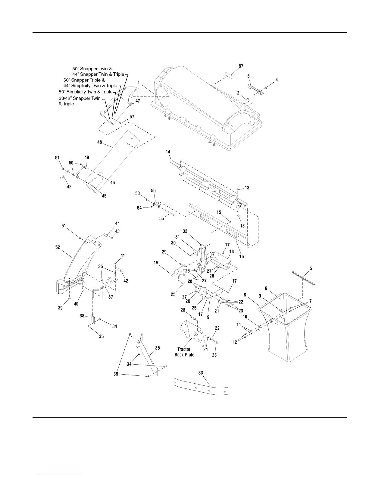
Triple Catcher Assembler 44" & 50"
NOTE: Unless noted otherwise,
use the standard hardware torque
specification chart.
1695354
The above parts group applies to the following Mfg. Nos.:
1695354 - Catcher
Briggs and Stratton Yard Power Products Group
Milwaukee, WI, USA. All rights reserved
2007Copyright © by Briggs and Stratton Corporation
4
TP 400-4787-00-AT-SMA
Page 5

Triple Catcher Assembler 44" & 50"
PART NO. DESCRIPTIONREF NO QTY.
COVER ASSEMBLY, Triple Catcher 1 1733546SM 1
SCREW, Truss Head Phillips, 10 - 24 x 3/4 2 1960404SM 6
HANDLE, Plastic 3 054537MA 2
NUT, Hex Lock, 10-24 w/Nylon Insert 4 1933896SM 6
CLIP, Tube Grass Bag 5 1733709SM 3
BAG, Triple Regular 6 1733695SM 3
BOLT, Carriage, 5/16 - 18 x 3/4, G5 7 1931333SM 6
HOOP, Triple 8 1733517SM 3
HANGER, Grass Bag 9 1703807ASM 3
CLAMP, Grass Bag Plain 10 1672023ASM 3
LOCKWASHER, Spring, 5/16 11 1917356SM 6
NUT, Hex, 5/16 - 18 12 1917372SM 6
SCREW, Hex Washer Head Taptite, 5/16 - 18 x 3/4 13 1664847SM 8
BRACKET, Tab Cross Support Triple 14 1733624ASM 1
NUT, Hex Whiz Lock Flange, 3/8 - 16 (Included in Ref. No. 68) 15 1928352SM 4
CHANNEL, Cross Support Triple 16 1733623ASM 1
CAPSCREW, Hex, 3/8 - 16 17 1921210SM 2
BRACKET, LOWER (Included in Ref. No. 68) 18 1703744ASM 1
SUPPORT, SIDE HITCH 19 1723067ASM 2
SPACER (Included in Ref. No. 68) 21 1668662SM 4
WASHER, Flat (Included in Ref. No. 68) 22 1924361SM 4
CAPSCREW, Hex Head, 1/2 - 13 x 2 1/2 (Included in Ref. No. 68) 23 1960462SM 4
PLATE, SIDE GRASS CATCHER 25 1723044ASM 2
LOCKWASHER, Spring, 3/8 (Included in Ref. No. 68) 26 1916965SM 2
NUT, Hex, 3/8-16 (Included in Ref. No. 68) 27 1916950SM 2
NUT, Hex, Lock 1/2-13 (Included in Ref. No. 68) 28 1960355SM 4
CAPSCREW, Hex Head, 3/8 - 16 x 1 1/4 29 1920415SM 2
CAPSCREW, Whiz, 3/8 - 16 x 1.00 (Included in Ref. No. 68) 30 1934654SM 4
PLATE, Reinforcement, Upright (Included in Ref. No. 68) 31 1733948ASM 1
SUPPORT, UPRIGHT 32 1734223ASM 1
BAFFLE, Blowout L.H. 50" Mower Deck 33 1716870ASM 1
BAFFLE, Blowout L.H. 44" Mower Deck 33 1716879ASM 1
BOLT, Carriage, 5/16 - 18 x 5/8 (Included in Ref. No. 68) 34 1931332SM 9
NUT, Hex Whiz Lock Flange, 5/16 - 18 (Included in Ref. No. 68) 35 1927557SM 9
BAFFLE, Blowout R.H. 50" Mower Deck 36 1726364ASM 1
BAFFLE, Blowout R.H. 44" Mower Deck 36 1731990ASM 1
ROD, Boot Mount, Deflector Prop, 44/50" 37 1733946SM 1
PLATE, Chute Rod (Included in Ref. No. 68) 38 1726578ASM 1
SCREW, Hex Head, 5/16 - 18 x 3/4 39 1960371SM 1
SCREW, Hex Whiz Lock Flange, 5/16 - 18 x 1-1/4 (Qty. of 2 included in Ref. No. 68) 40 1930595SM 3
NUT, Hex Flange Two-Way Lock, 5/16 - 18 41 1935048SM 1
STRAP, Hood 42 2171600SM 2
BOLT, Carriage, 1/4 - 20 x 5/8 43 1960252SM 1
PIN, Latch 44 054563MA 1
Footnotes
The above parts group applies to the following Mfg. Nos.:
1695354 - Catcher
Briggs and Stratton Yard Power Products Group
Milwaukee, WI, USA. All rights reserved
2007Copyright © by Briggs and Stratton Corporation
5
TP 400-4787-00-AT-SMA
Page 6

Triple Catcher Assembler 44" & 50"
NOTE: Unless noted otherwise,
use the standard hardware torque
specification chart.
1695354
The above parts group applies to the following Mfg. Nos.:
1695354 - Catcher
Briggs and Stratton Yard Power Products Group
Milwaukee, WI, USA. All rights reserved
2007Copyright © by Briggs and Stratton Corporation
6
TP 400-4787-00-AT-SMA
Page 7

Triple Catcher Assembler 44" & 50"
PART NO. DESCRIPTIONREF NO QTY.
SCREW, 1/4 - 20 x 1 45 004x71MA 1
SCREW, 1/4 - 20 x 1/2 46 004x24MA 1
ELBOW, Upper Tube Poly 47 1733885SM 1
TUBE, Clear Poly 48 1732552SM 1
HANDLE, Connect Tube 49 054416ZMA 1
NUT, Hex Keps, 1/4 - 20 50 1928372SM 2
NUT, Hex Flange Top-Lock, 1/4 - 20 51 1930642SM 2
TUBE, Boot Poly 52 1734327SM 1
CLIP, Hair Pin (Included in Ref. No. 68) 53 1960074SM 2
SCREW, Hex Washer Head Taptite, 1/4 - 20 x 1/2 54 1925003SM 4
PIN, Cover Hinge (Included in Ref. No. 68) 55 054407ZMA 2
PIVOT, Hinge 56 1733504ASM 2
SCREW, 1/4 x 3/4 (Included in Ref. No. 68) 57 26x239MA 1
STICKER, Serial w/Bar Code (Not Serviceable) 58 ----- 1
MYLAR OVERLAY 59 ----- 1
DECAL, Warning Thrown Objects 67 1732819SM 1
68 1660954SM 1
HARDWARE BAG (Not Shown. Includes Ref. Nos. 15, 18, 21, 22, 23, 26, 27, 30, 31, 34, 35,
38, 40, 53, 55 & 57)
Footnotes
The above parts group applies to the following Mfg. Nos.:
1695354 - Catcher
Briggs and Stratton Yard Power Products Group
Milwaukee, WI, USA. All rights reserved
2007Copyright © by Briggs and Stratton Corporation
7
TP 400-4787-00-AT-SMA
Page 8

Page 9

Page 10

Page 11

Hex Head Capscrew
Hex Nut
Lockwasher
Washer
Carriage Bolt
Hardware Identification & Torque Specifications
Screw, 1/2 x 2
Body
Diameter
Body
Length
Inside
Diameter
Nut, 1/2”
No
Marks
3/8” Bolt or Nut
Wrench—9/16”
3/8
5/16” Bolt or Nut
Wrench—1/2”
5/16
1/4” Bolt or Nut
Wrench—7/16”
1/4
1/2” Bolt or Nut
Wrench—3/4”
1/2
DIA.
7/16
DIA.
7/16” Bolt or Nut
Wrench (Bolt)—5/8”
Wrench (Nut)—11/16”
Wrench & Fastener Size Guide
0
1/4 3/4
1/2
1
1/4 3/4
1/2
2
1/4 3/4
1/2
3
1/4 3/4
1/2
4
Common Hardware Types
Torque Specification Chart
FOR STANDARD MACHINE HARDWARE (Tolerance ± 20%)
Hardware
Grade
Size Of
Standard Hardware Sizing
When a washer or nut is identified as 1/2”, this is the
Nominal size
second number is present it represent the
When bolt or capscrew is identified as 1/2 - 16 x 2”, this
means the
second number represents the
example, and the final number is the
bolt or screw (in this example 2 inches long).
, meaning the
Nominal size
inside diameter
, or
body diameter
threads per inch
is 1/2 inch; if a
threads per inch
is 1/2 inch; the
body length
(16 in this
of the
The guides and ruler furnished below are designed to
help you select the appropriate hardware and tools.
Hardware ft/lbs Nm. ft/lbs Nm. ft/lbs Nm.
8-32
8-36
10-24
10-32
1/4-20
1/4-28
5/16-18 11 15.0 17 23.1 25 34.0
5/16-24 12 16.3 19 25.8 27 34.0
3/8-16 20 27.2 30 40.8 45 61.2
3/8-24 23 31.3 35 47.6 50 68.0
7/16-14 30 40.8 50 68.0 70 95.2
7/16-20 35 47.6 55 74.8 80 108.8
1/2-13 50 68.0 75 102.0 110 149.6
1/2-20 55 74.8 90 122.4 120 163.2
9/16-12 65 88.4 110 149.6 150 204.0
9/16-18 75 102.0 120 163.2 170 231.2
5/8-11 90 122.4 150 204.0 220 299.2
5/8-18 100 136 180 244.8 240 326.4
3/4-10 160 217.6 260 353.6 386 525.0
3/4-16 180 244.8 300 408.0 420 571.2
7/8-9 140 190.4 400 544.0 600 816.0
7/8-14 155 210.8 440 598.4 660 897.6
1-8 220 299.2 580 788.8 900 1,244.0
1-12 240 326.4 640 870.4 1,000 1,360.0
1. These torque values are to be used for all hardware
excluding: locknuts, self-tapping screws, thread forming
screws, sheet metal screws and socket head setscrews.
2. Recommended seating torque values for locknuts:
a. for prevailing torque locknuts - use 65% of grade 5
b. for flange whizlock nuts and screws - use 135% of
3. Unless otherwise noted on assembly drawings, all torque
values must meet this specification.
SAE Grade 2 SAE Grade 5 SAE Grade 8
in/lbs in/lbs
19
2.1
20
2.3
27
3.1
31
3.5
66
7.6 8 10.9 12 16.3
76
8.6 10 13.6 14 19.0
torques.
grade 5 torques.
30
31
43
49
NOTES
in/lbs
3.4
3.5
4.9
5.5
41
43
60
68
4.6
4.9
6.8
7.7
Page 12

 Loading...