

Page 1
TAKE-OFF KIT
311
POWER STAKE-OFF
For operation of Rotary Mower and Sickle Bar attach-
a power take-off attachment is required. This
consists of the power take-off assembly,
for bevel gear shaft, drive belt, belt guard, and belt
packaged in one carton.
For ease of attachment follow the step; outlined
below.
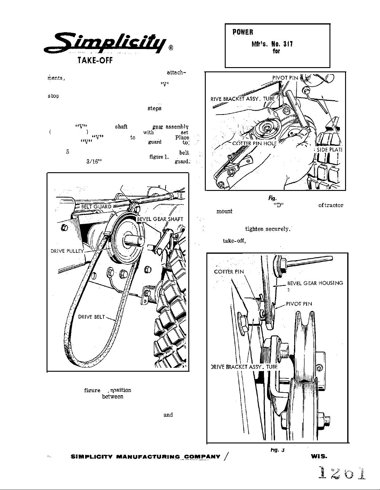
1. Mount
see figure 1
screw.
drive belt on
inside surface of side plate nearest drive pulley. See‘
figure
guard to the guard support as shown in
approximately
pulley to
and secure in place with key and
Hub of
for mounting bolt location.
pulley is
pulley and mount belt
clearance between belt and hard;:
BELT GUARD SUPPORT
of bevel
face inward.
pulley
support
Attach the
Allow
LANDLORD RIDING TRACTOR
BEVEL GEAR HOUSING SIDE PlqT’
4. Remove hex cap screw
and
See figure 4. Position the pivot bar assembly flush
against bottom of lift quadrant and re-install hex
cap screw and
drive pulley on bevel gear shaft, driven pulley of
power takg-off, and idler pulley, and adjust driving
pulley if necessary.
bracket in place under lift lever quadrant.
\
from frame
Check alignment of
Fig. I
2. Holding the power take-off assembly in left hand
as shown in
bracket assembly
side plates. Align the holes in side plates with the
hole in drive bracket assembly tube and insert
pivot pin through holes in side plates
bracket assembly tube.
3. Push pivot pin through the holes in bracket and
tube until the position of cotter pin hole in pivot
pin is as shown in figure 3. Secure in position with
cotter pin furnished.
the bevel gear housing
drive
SIDE PLATE
PORT WASHINGTON.
Page 2
POWER TAKE-OFF
Page 3

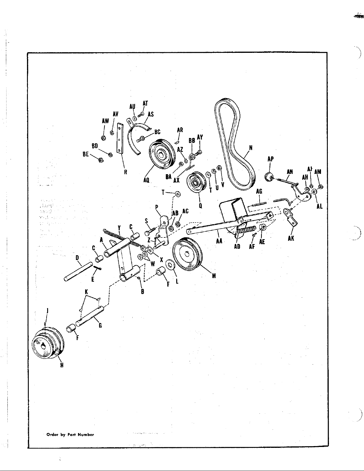
POWER TAKE-OFF
by
Reference
Letter
A 154228 Bracket Assembly, Drive
B 727006
C
D 154233 Rod, Pivot
E 122001 Pin, Cotter
F 154258 Bearing, Needle
G
J
L
N 106390
R
T 119002 Washer, Plain,
V
W
X 154368
Y
Z
AA
AB 119001 Washer, Plain,
AC 717510 Nut, Lock, Hex Hd., Full,
AD
AE 8191022
AF 113001 Screw, Set. Sq. Hd. Cup Pt.,
AG 154364
AH
AJ
AK
AL
AM 111510
AN
AR 8061081
AS
AT 105005
AU 719001 Washer, Plain,
AV
AW
Ax
AY 705031 Capscrew,
AZ 120002
BA
BB
BC
BE
Part NO. Description
8051038
157116
1.57116
113503 Screw, Set, Cup Point, Socket
108182
154308
154360
154534
157050
105016
120002
111003
119001
154369
122009
8191045
719002 Washer, Plain,
711511 Nut, Lock, Hex
154362
719001 Washer, Plain,
154356
122005
157121
157132
120002
111003
8021014
111003 Nut, Full, Hex,
119001
705007
720001
717001
Fitting, Grease
Bushing
Shaft, Power Take-Off
Pulley, Power Take-Off
Washer
Pulley
Belt, “V”, Power Take-Off
Lever Assembly, Idler
Pulley, Idler
Guard Support
Capscrew, Hex Hd.,
Washer, Lock,
Nut, Hex, Full,
Washer, Plain,
Clip, Spring
Spring, Tension
Pin, Cotter,
Guide Assembly, Rod
Spring
Collar, Set
Rod Assembly, Clutch
Pivot Bar Assembly
Nut, Lock, Hex Hd. Full,
Lever Assembly, Clutch
Knob
Pulley
Guard Assembly, Belt
Capscrew,
Washer, Lock,
Nut, Hex, Full,
Stop, Belt
Washer, Lock,
Washer, Plain,
Lockwasher, S/16”
Full,
16 N. C.
16 N. C.
- 16 N.C.
16 N. C.
16 N.C.
18 N. C.
- 16 N.C. x1-1/4" lg.
lg.
16 N.C.
- 20 N.C.
18 N. C.
- 16 N. C.
1” lg.
lg.
1"
lg.
lg.
Page 4

5. Mount “V” belt in place on driven
in figure 5 and attach spring
shown
hole in the
spring holder and hook other end of the spring to the
lever spring holder. Mount belt stop as shown
with
bolt, flat washer, lockwasher and hex nut.
When idler pulley is engaged, l/S” clearance between
belt stop nud back of
uode,r idler pulley. See figure 5.
required. Note: “V”
“RELEASE” POSITION
CLUTCH LEVER ASSEMBLY
“DRIVE”, POSITION
4
BELT GUARD SUPPORT MTG. BOLTS
PULLEY
SPRING
DRIVEN PULLEY
The power take-off is lubricated by means of one
grease fitting located
drive
‘bracket assembly. Occasionally apply grease by
of a standard grease gun loaded with auto-
type grease. Be sure to wipe dirt and grit
from grease fitting before applying grease gun. Lu-
bricate all pivot points and idler pulley bearings with
SAE 20 oil every few hours of operation.
OPERATION
Operation of the power take-off is controlled by
of the clutch lever assembly. See figure
4. When the clutch lever is in the forward raised
position, the clutch rod releases the tension holding
the idler pulley against the drive belt, and power
will not be
power take-off assembly. when the clutch
to the driven pulley of the
iS
the back, depressedposition, theclutchrodapplies
tension to the idler pulley and as the idler pulley
takes-up the slack in the drive belt, power is trans-
mitted from the drive pulley on bevel gear box shaft
to the
pulley of the power take-off. Figure 4
shows clutch lever in drive position.
Fig. 5
ADJUSTMENT
At points “A” and “B” of figure 4, check tightness of
hex nut to be
that clutch lever assembly and
clutch rod are free to pivot without binding.
Place clutch lever in “drive” position and observe
clearance between collar
bracket. This clearance should normally be ap-
proximately
inch; at this setting the idler pulley
should be snugly against the drive belt. If additional
tension is required, release clutch lever and loosen
set screw on collar
collar farther back on
clutch rod. Retighten set screw in collar and put
clutch lever in drive position. Recheck clearance.
The tension of the idler pulley against the drive belt
must be sufficient to operate whichever tractor at-
is being used. ,Any additional
iS
unnecessary and will
of belts and idler pulley bearings.
Form MF-49
 Loading...