

Page 1
Installation
2000 RPM Rear PTO
Mfg. No.
1692891
Instructions
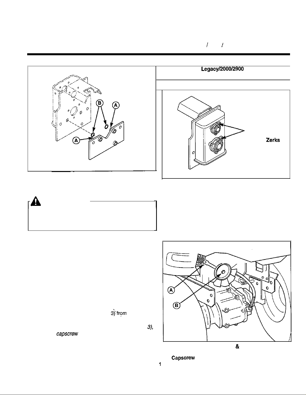
Figure 1. Install O-Rings
A. Mounting Plate Alignment Pins
B. O-Rings
For Legacy / 2000 / 2900 Series Garden Tractors
This kit equips
with a 2000 RPM rear PTO.
Figure 2. Grease Bearings
Series tractors
I
Grease Front
and Back
Bearing
Grease Zerks
WARNING
Before beginning installation, engage the parking
brake, shut the PTO off, turn the ignition off, and
remove the key.
ASSEMBLY
1. Install the two o-rings (B, Figure 1) on the mounting
plate alignment pins (A)
2. Grease the front and back bearing grease zerks
(see Figure 2).
INSTALLATION
install PTO Box
1. Remove the rear bumper and mounting hardware.
2. Remove the set screw (A, Figure
pump shaft and fan assembly.
NOTE: For easier access to the set screw (A, Figure 3),
remove the
remove the fan.
3. Remove the fan and shaft assembly from the output
shaft.
(B, Figure 3) retaining the fan, and
the hydro
Figure 3. Remove Hydro Fan
A. Setscrew
B.
Shaft Assembly
Page 2
Installation Instructions
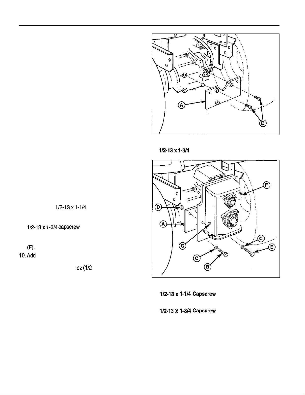
4. Attach the mounting plate (A, Figure 4) to the transmission using two socket-head capscrews (B) as
shown. Torque capscrews to 60-65 ft. Ibs. DO NOT
over-torque. Be sure the alignment pins and O-rings
are facing toward the back of the tractor.
5. Grease the hydro pump output shaft with lithium
grease.
6. Align the input shaft of the PTO box with the output
shaft of the hydro pump and slide the PTO box into
position (see Figure 5). Be sure to push the PTO box
fully into position so that the alignment pins support
the weight of the box; DO NOT allow the hydro pump
output shaft to support the full weight of the PTO box.
7. Secure the PTO box to the mounting plate (A, Figure
5) using two
ers (C), and nylon locknuts (D).
8. Secure the PTO box to the transmission using one
2000 RPM Rear PTO
Figure 4. Attach Mounting Plate
A. Mounting Plate
B.
Socket Head Capscrews
(C). Torque to 60-65 ft. Ibs. DO NOT over-torque.
9. Remove the fill level plug (G, Figure 5) and oil fill plug
runs out of the fill level hole. The PTO box oil capaci-
ty is approximately 16
11. Reinstall the fill level and oil fill plugs.
quart).
Figure 5. Mount and Secure PTO Box
A. Mounting Plate
B. 1/2-13x
C. Lo&washer
D. Locknut
E.
F. Fill Plug
G. Fill Level Plug
2
l-3/4
Page 3

2000 RPM Rear PTO
Install Rear PTO Switch
1. Using the template (A, Figure 6) and a scratch awl,
scribe the switch hole pattern into the lower left corner of the dashboard as shown.
2. Drill out the corners,of the area to be cut out.
3. Cut the plastic dashboard along the scribed pattern.
BE CAREFUL NOT TO CUT AWAY TOO MUCH
MATERIAL. If the hole is made too large, the switch
will pull out of the dashboard. Excess material can
be easily removed with a flat file.
NOTE:
material, the template can be used as a switch mounting
p/ate,
hole and secure the template to the dashboard using two
4. Install the switch into the dashboard. Test the fit by
Connect Wiring
1. Locate the rear PTO switch plug on the main wiring
2. Connect the rear electric PTO clutch to the plug (A,
you should accidentally remove too much
Remove an additional l/16” of material from the
truss head screws, washers, and nuts.
activating the,switch several times.
harness behind the dashboard. Remove the jumper
(A, Figure 7) from the harness plug and connect the
harness to the rear PTO switch.
Figure 8) located on the rear wire harness under the
right rear wheel well.
Figure 6. Switch Template
A. Switch Hole Template
Installation Instructions
Burnish PTO Clutch
After installing the PTO box and the attachment to be
used with the PTO box, the electric clutch must be burnished. The purpose of burnishing the electric clutch is
to burn off coatings on parts that are there to prevent
corrosion before initial use. Burnishing is necessary to
assure correct stopping times.
1. Select a safe area to operate the PTO. With the
parking brake engaged, the PTO switch disengaged,
and an operator in the seat, start the tractor engine.
Run the engine at full throttle.
2. Engage the PTO switch and run the attachment for
fifteen seconds. Disengage the PTO switch and wait
for the PTO to stop.
3. Repeat step 2 ten times.
Figure 7. Connect PTO Switch
A. Jumper
Seat Deck Removed
Figure 8. PTO Clutch Plug Location
A. PTO Clutch Plug
3
Page 4
2000 RPM Rear PTO
Page 5
2000 RPM Rear PTO
Installation Instructions
REFNO. PARTNO.
1716434
2
3
4
7
8
9
11
12
13
14
15
16
17
18
19
20
21
22
23
24
25
26
27
28
29
30
31
32
33
34
37
38
39
40
41
42
43
44
45
46
48
49
50
51
52
*
1960373
1717639
1717638
1716950
1716392
1717599
154096
1716401
1676829
1923362
1919326
156150
1921977
1921978
1933468
1678998
1676999
1921968
1678997
1709199
1718585
1716383
1704314
1716387
1929477
1927187
1716431
1717641
1717640
1716403
905856
1716427
1716393
1718475
1716955
1916951
1916966
1921176
1921535
1960597
176111
I673452
1673453
901652
1716402
1924856
1717078
1654930
1709905
1718938
1716332
1930531
1960096
1930627
QTY.
2
6
2
2
1
1
1
1
2
8
14
8
2
2
2
1
1
1
6
2
1
2
1
1
2
3
2
2
1
2
1
1
1
2
2
2
DESCRIPTION
Bearing
Taptite Screw, 5/l 6-l 8 x 1
O-Ring, 1.610 ID
ID
Sprocket Assy, 19 Tooth
x 46 Pitches
Shaft Assy
Flex Coupling
Locknut,
Washer,
Spacer
Capscrew, 5/l 6-l 8 x I
Capscrew, 5/i 6-18 x 2
Washer,
Bushing
Hub Assy
Capscrew,
Washer,
Electric Clutch
Spacer
Shaft Assy
Grease
Fan -
Taptite Screw,
Taptite Screw, 3/8-16x 1
Bearing-Flange
Shaft
Spacer
Sprocket Assy, 34 Tooth
Spring Lock Kit
Plate Assy
Nut,
Lockwasher,
Capscrew, 1/2-13x
Capscrew, 1/2-13x l-3/4
Socket Hd. Capscrew, 1/2-l 3 x l-3/4
O-Ring
Pipe Plug,
Elbow,
Pipe Plug,
Case Assy
Taptite Screw,
Bushing, Rubber
Breather Assy
Retaining Ring
Switch Mounting Template
Truss Hd. Screw, #IO-32 x
Washer
Nut, #IO-32
6
1.372 ID
NPT
NPT, Square Hd
x 2
x
*Not Shown
5
Page 6

Installation Instructions
2000 RPM Rear PTO
NOTES
MANUFACTURING, INC.
500 N Spring Street / PO BOX 997
Port Washington, WI 53074.0997 USA
Form No. 1719589-01
1998 Simplicity Manufacturing, Inc. All Rights Reserved
 Loading...