

Page 1
5100777
Rev. 07/2006
TP 200-7302-00-CI-S
WARNING
Before beginning any service work turn off the
PTO, set the parking brake, turn off the ignition,
and disconnect the spark plug wire(s).
1. Park the machine on a flat, level surface and engage
the parking brake. Disengage the PTO switch, turn
off the engine and remove the key from the ignition.
2. Save all the hardware that is being removed.
Remove the floor pan and the front shocks.
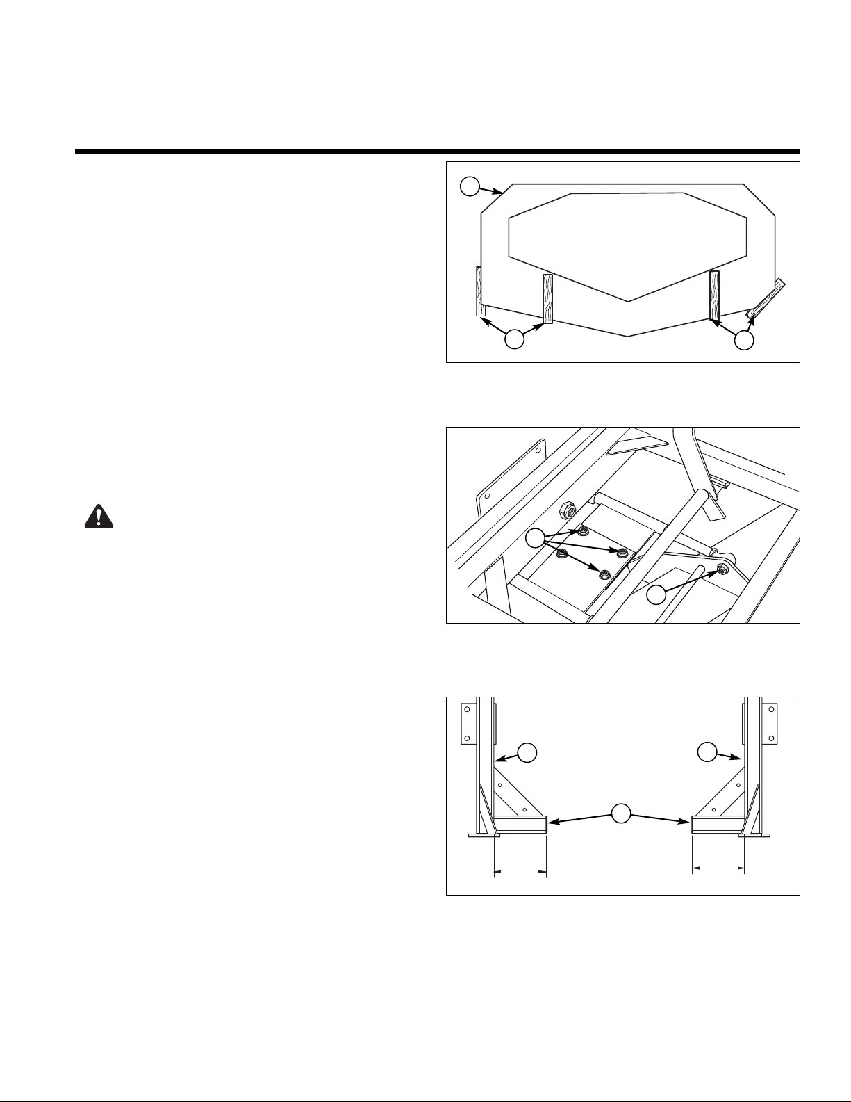
3. Refer to Figure 1. Place approximately 8” of wooden
blocking under the mower deck and lower the deck
onto the blocking. Position jack under the front of the
machine. Lift the front caster wheels off the ground
and place approximately 4” of wooden blocking
between the mower deck and the frame. Lower the
jack down until the frame rests on the blocking.
Remove the jack.
4. Cut the (3) existing black tie wraps that fasten the
headlight wire harness to the front of the frame.
Refer to Figure 9. Remove the 3/4” hardware holding
the caster pivot frame and remove the caster pivot
frame assembly.
5. Loosen the (4) deck puller bar adjustment bolts (A,
Figure 2). Remove the (4) mount hardware (B) that
connect the deck puller bar to the front end and the
deck. Remove the deck puller bar and set aside
6. Refer to Figure 3. Cut the front cross member (A)
within 4-1/4” to 4-1/2” from the inside of the frame rail
(B). NOTE: Keep the cut perpendicular to the top of
the frame rail.
Installation
Instructions
Front End Repair Kit
Part No. 5600079
For Simplicity Citation Models
Kit Contents:
Front end No. Qty. Description
5402029C 1 Front End Weldment
5402041C 2 Bracket, Bolt on
5022098 4 Cap, Plastic
5025156 10 Washer, 3/8” SAE
5025013X10 4 Bolt, 3/8-16 X 1-1/4”
5025013X20 4 Bolt, 3/8-16 X 2-1/2”
5025013X28 4 Bolt, 3/8-16 X 3-1/2”
5025394 10 Nut, 3/8-16 Hex Nylock Flange
5021072 2 Seal, Grease
5025203X10 2 Pin, Cotter
5047489 1 Spacer
5022852 1 Bearing
5100358 1 Bearing
5025265X52 1 Bolt, 3/4-16 X 6-1/2”
5025284 1 Nut, 3/4-16 Hex Nylon Lock
5025160 2 Washer, 3/4 SAE
5049949C 1 Caster Pivot Frame
5100772 1 Tie Wrap, 15” Long, UV Black
1
© Copyright 2006 Ferris Industries. All Rights Reserved.
Figure 1. Position of Wooden Blocks
A. Wooden Blocks
B. Mower Deck
A
B
Figure 2. Deck Puller Bar
A. Puller Bar Adjustment Bolts
B. Mount Hardware
A
B
4.50
4.25
4.50
4.25
Figure 3. Cut Front Cross Member
A. Front Cross Member
B. Frame Rail
4-1/4”
4-1/2”
B
B
A
4-1/4”
4-1/2”
A
Page 2
2
Installation Instructions
Kit Part No. 5600079
5100777
Rev. 07/2006
TP 200-7302-00-CI-S
© Copyright 2006 Ferris Industries. All Rights Reserved.
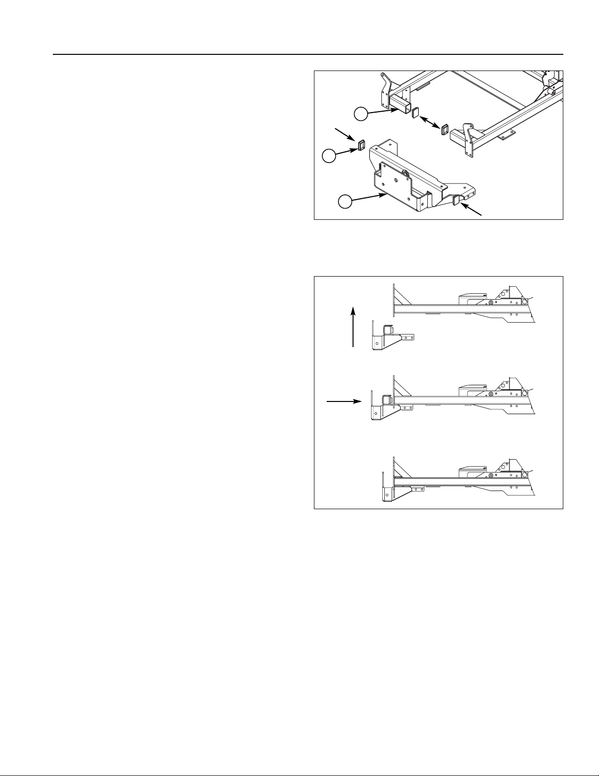
8. Position from the bottom the new front end against
the frame as shown in Figure 5. Then slide toward
the rear of the machine until the c-channel of the
new front end rests over the front cross member that
was cut.
Figure 5. Install New Front end
7. Install the plastic end caps (B, Figure 4) in the ends
of the cut cross member (A) and the new front end
(C).
C
B
A
Figure 4. Install Plastic End Caps
A. Cut Cross Member
B. Plastic End Cap
C. New Front end
Page 3

3
Installation Instructions
Kit Part No. 5600079
5100777
Rev. 07/2006
TP 200-7302-00-CI-S
© Copyright 2006 Ferris Industries. All Rights Reserved.
9. Loosely install the rear brackets (F, Figure 6) to the
new front end with the 3/8-16 X 1-1/4” bolts (C), 3/816 X 3-1/2” bolts (B), 3/8 SAE washers (D), and 3/816” nylon flange nuts (E). Snugly clamp the front of
the new front end to the cross member using (2) Cclamps (See Figure 7).NOTE: Do not over tighten the
clamps.
Figure 6. Loosely Install the Rear Brackets
A. 3/8-16 X 2-1/2 Bolt
B. 3/8-16 X 3-1/2 Bolt
C. 3/8-16 X 1-1/4 Bolt
D. 3/8” SAE Washer
E. 3/8-16 Nylon Flange Nut
F. Rear Bracket
B
A
C
F
E
E
D
D
Figure 7. C-Clamp Positions
9. Snugly clamp the top of bracket and the bottom of
the new front end to the frame rail using (2) more Cclamps. Tighten the bottom bracket bolts. Refer to
Figure 8. Using the front top hole as a guide drill a
3/8” hole through the frame and install 3/8-16 X 21/2” bolts and 3/8-16 flange nuts on both sides of the
frame. Tighten the bracket hardware (Do Not
Exceeds 35 ft lbs of Torque) and remove clamps that
were holding it.
10. Drill the front mounting holes: Use the holes in the
new front end as guide, drill the top holes from the
top and the bottom holes from the bottom to insure
the correct alignment. Install 3/8-16 X 3-1/2” bolts
(A, Figure 6) and 3/8-16 flange nuts (E, Figure 6).
Tighten the hardware and remove the clamps.
Bottom of Frame
Top & Side
Figure 8. Drill 3/8” Holes
Drill Holes
Here
FRONT
FRONT
Page 4

4
Installation Instructions
Kit Part No. 5600079
5100079
Rev. 07/2006
TP 200-7302-00-CI-S
© Copyright 2006 Ferris Industries. All Rights Reserved.
11. Remove the caster wheels yokes from the old front
end assembly. Refer to Figure 9, install the removed
yokes (G) and spacer (I) in to the new front end
assembly. If needed, clean and re-grease tapered
bearings before installation. Install the new caster
pivot frame (H) to the frame with the new 3/4”
hardware (J, K, L) provided.
21
22
23
23
Figure 9. Caster Pivot Frame Assembly
A. Cap
B. Slotted Nut
C. Cotter Pin
D. 3/4” SAE Washer
E. Bearing
F. Grease Seal
G. Caster Yoke
H. New Caster Pivot Frame
I. Spacer, .75 x 1.00 x 2.38
J. 3/4-16 x 6-1/2” Bolt
K. 3/4” SAE Washer
L. 3/4-16” Nylon Nut
A
B
C
E
E
F
G
I
H
D
Figure 10. Reinstall the Puller Bar
A. Bolt
B. Ball Joint
C. Washer
D. Frame
E. Nut
12. Refer to Figure 10. Reinstall the mower deck puller
bar (front of the puller bar install on the inside of the
new front end). Install hardware removed previously.
Tighten the puller bar adjustment bolts (A, Figure 2).
13. Reinstall the floor pan and the front shocks.
NOTE: Use the (3) 15” tie wraps to fasten the headlight
wire harness back to the frame.
J
K
L
B
A
C
E
D
 Loading...