

Page 1

How to use this file...(Operators Manuals)
————————————————————————————————————————————–––
Instructions for
Print Vendors (Paper Manuals)
Paper Size: * 11 x 17
* Body—50 lbs brilliant white offset or equivalent.
* Cover—on pre-printed two-tone “Swash” stock.
Press: * Body—1-color, 2-sided
* Cover imprint —1-color, 1-sided
Bindery: * Saddle Stitch, Face Trim, 3-Hole Drill
* Face Trim
COVERS: * This file contains several manuals, which differ only in their covers.
* Covers are all present at the beginning of this file.
* Back cover for a particular manual is the page IMMEDIATELY AFTER the front cover.
• Check the front cover for the individual part number (typically a 171xxxx number).
BODY: • The body of the manual is identical, regardless of the cover used.
* REMEMBER: ODD number pages are ALWAYS right hand pages, and EVEN number are ALWAYS
left hand pages.
General: * This instruction page is NOT part of the manual and must NOT be printed.
• Pages labeled with the text “THIS PAGE INTENTIONALLY BLANK” are placement pages ONLY,
and should NOT be printed.
————————————————————————————————————————————–––
If you have further questions on how to utilize this file, please contact
Simplicity Technical Publications Department at (414) 284-8650.
Page 2

THIS PAGE INTENTIONALLY BLANK
Page 3
Replacement
OPERATOR’S
MANUAL
SunStar / 1900 / 2900 Series
18HP Hydro Tractors
Mfg. No. Description
1692521 SunStar, 18HP Hydro
1692523 1918H, 18HP Hydro
1692525 2918H, 18HP Hydro
20HP Hydro Tractors
Mfg. No. Description
1692454 SunStar, 20HP Hydro
1692456 SunStar, 20HP Hydro
1692458 1920H, 20HP Hydro
1692460 1920H, 20HP Hydro
1692505 2920H, 20HP Hydro
1692507 2920H, 20HP Hydro
48” Mower Decks
Mfg. No. Description
1690986 48” Mower Deck
1691183 48” Mower Deck
60” Mower Decks
Mfg. No. Description
1691339 60” Mower Deck
1691344 60” Mower Deck
1714289-01
1714298-01
1714411-01
Rev 2/1995
TP 100-1424-01-SS-SMA
Note: This Replacement Operator’s Manual is a reprint of a manual no longer in production, but
contains the same information as the Operator’s Manual furnished with the original tractor.
Page 4

MANUFACTURING, INC.
500 N Spring Street / PO Box 997
Port Washington, WI 53074-0997
www.simplicitymfg.com
© Copyright 1998, Simplicity Manufacturing, Inc.
All Rights Reserved. Printed in USA.
Page 5

TRACTOR & MOWER IDENTIFICATION.....................2
SAFETY RULES............................................................3
SAFETY DECALS .........................................................5
FEATURES & CONTROLS...........................................6
Tractor Controls....................................................................6
Safety Interlock System........................................................7
OPERATION..................................................................8
General.................................................................................8
Mower Installation & Removal.............................................8
Checks Before Starting.......................................................10
Starting The Engine............................................................10
Selecting Axle Speed Range (20 HP Models Only) ...........10
Operation............................................................................11
Stopping the Tractor...........................................................11
Pushing the Tractor by Hand .............................................11
MOWING PATTERN & TIPS.......................................12
NORMAL CARE ..........................................................13
Schedule.............................................................................13
Raising the Hood ...............................................................13
Checking/Adding Gasoline .................................................13
Checking Tire Pressure......................................................13
Checking the Fuel Filter......................................................13
Lubrication..........................................................................14
Checking Transmission Fluid..............................................15
Changing Transmission Fluid & Filter.................................16
Battery Maintenance...........................................................16
Servicing the Mower Blades...............................................17
STORAGE ...................................................................18
Temporary Storage.............................................................18
Long Term Storage.............................................................18
Starting After Long Term Storage.......................................19
TROUBLESHOOTING & REPAIR...............................20
General...............................................................................20
Troubleshooting The Tractor ..............................................20
Troubleshooting The Mower...............................................21
Checking the Battery ..........................................................21
Charging A Completely
Discharged Battery..........................................................22
Jump Starting with
Auxiliary (Booster) Battery...............................................22
Bulb Replacement ..............................................................23
ADJUSTMENTS ..........................................................24
Seat Adjustment .................................................................24
Brake Adjustments .............................................................24
Front Clutch Adjustment.....................................................25
Leveling the Mower ............................................................25
Adjustments for the 60” Mower...........................................26
Blade Brake Adjustment.....................................................26
BELT REPLACEMENT................................................27
Tractor PTO Belt.................................................................27
Mower Belt..........................................................................27
SPECIFICATIONS.......................................................28
PARTS & ACCESSORIES ..........................................30
Common Replacement Parts..............................................30
Maintenance Items .............................................................30
Optional Accessories..........................................................31
Technical Literature............................................................31
INTERNATIONAL SYMBOLS.....................................32
1
Table Of Contents
NOTE: In this manual, “left” and “right” are referred to as seen
from the operating position.
WARNING
Engine exhaust from this product contains
chemicals known, in certain quantities, to cause
cancer, birth defects, or other reproductive
harm.
Page 6
2
Tractor & Mower Identification
Record your model number, manufacturer number and
engine serial number in the space provided for easy reference. The models and manufacturer numbers covered
in this manual are listed on the front cover.
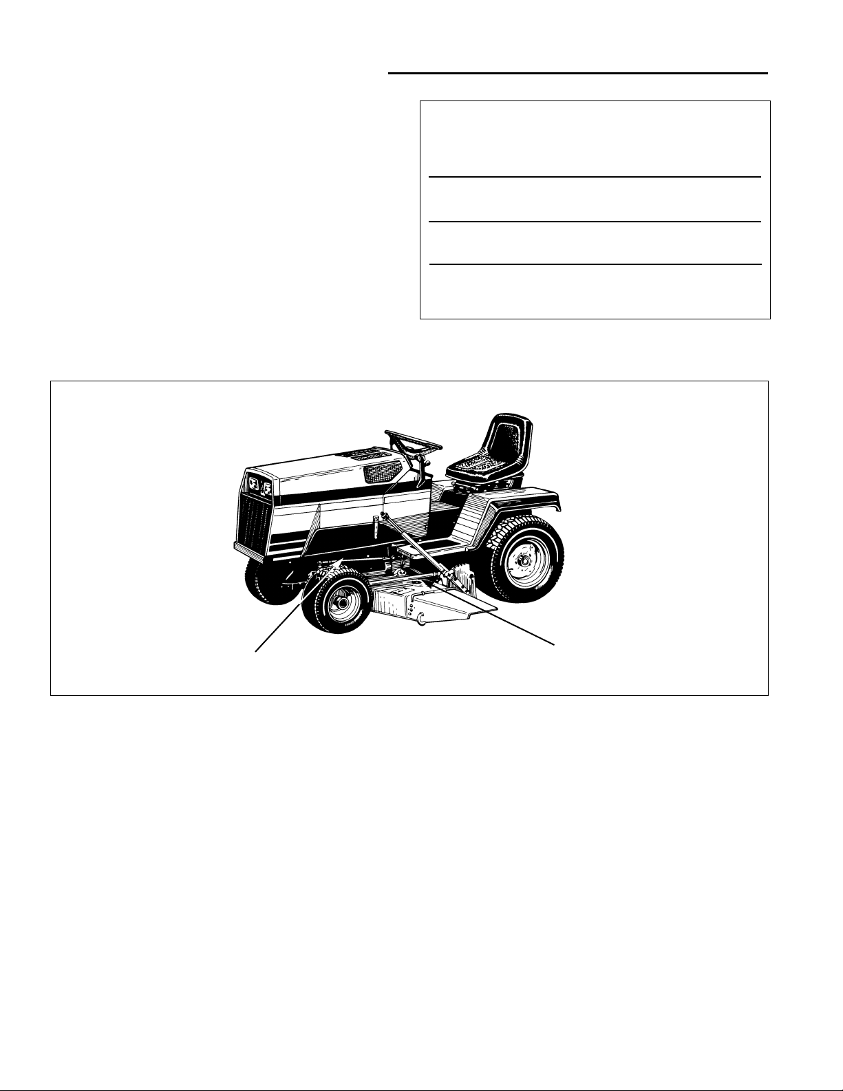
The tractor I.D. tag is located on the left-side, front of the
frame, as shown below. The mower deck I.D. tag is also
on the left side, on top of the mower deck, towards the
rear.
Refer to the engine Owner’s Manual for location of
engine serial number.
Be sure to fill out and return the Warranty Registration
Card supplied with your tractor.
MODEL REFERENCE
Model Number:
Manufacturer Number:
Engine I.D. Number:
Dealer Name/Date Purchased:
Figure 1. Tractor & Mower Identification Tags
Tractor
Identification Tag
Mower
Identification Tag
Page 7

GENERAL OPERATION
• Read, understand, and follow all instructions in the
manual and on the unit before starting.
• Only allow responsible adults, who are familiar with
the instructions, to operate the unit.
• Clear the area of objects such as rocks, toys, wire,
etc., which could be picked up and thrown by the
blade(s).
• Be sure the area is clear of other people before mowing. Stop unit if anyone enters the area.
• Never carry passengers.
• Do not mow in reverse unless absolutely necessary.
Always look down and behind before and while travelling in reverse.
• Be aware of the mower discharge direction and do
not point it at anyone. Do not operate the mower
without either the entire grass catcher or the deflector
in place.
• Slow down before turning.
• Never leave a running unit unattended. Always
disengage the PTO, set parking brake, stop engine,
and remove keys before dismounting.
• Turn off the PTO switch to disengage the blades
when not mowing.
• Stop engine before removing grass catcher or
unclogging chute.
• Mow only in daylight or good artificial light.
• Do not operate the unit while under the influence of
alcohol or drugs.
• Watch for traffic when operating near or crossing
roadways.
• Use extra care when loading or unloading the unit
into a trailer or truck.
SLOPE OPERATION
Slopes are a major factor related to loss-of-control and
tip-over accidents, which can result in severe injury or
death. All slopes require extra caution. If you cannot
back up the slope or if you feel uneasy on it, do not mow it.
Do
• See your authorized dealer for recommendations of
wheel weights or counterweights to improve stability.
• Mow up and down slopes, not across.
• Remove obstacles such as rocks, tree limbs, etc.
• Watch for holes, ruts, or bumps. Uneven terrain could
overturn the unit. Tall grass can hide obstacles.
• Use slow speed. Choose a low gear so that you will
not have to stop or shift while on the slope.
• Use extra care with grass catchers or other attachments. These can change the stability of the unit.
• Keep all movement on the slopes slow and gradual.
Do not make sudden changes in speed or direction.
Do Not
•
Do not
start or stop on a slope. If tires lose traction,
disengage the blade(s) and proceed slowly straight
down the slope.
•
Do not
turn on slopes unless necessary, and then,
turn slowly and gradually downhill, if possible.
•
Do not
mow near drop-offs, ditches, or embankments. The mower could suddenly turn over if a
wheel is over the edge of a cliff or ditch, or if an edge
caves in.
•
Do not
mow on wet grass. Reduced traction could
cause sliding.
•
Do not
try to stabilize the unit by putting your foot on
the ground.
•
Do not
use grass catcher on steep slopes.
3
Safety Rules
Read these safety rules and follow them closely. Failure to obey these rules could result in loss of control of
rider, severe personal injury or death to you, or bystanders, or damage to property or equipment. This
mowing deck is capable of amputating hands and feet and throwing objects. The triangle in text
signifies important cautions or warnings which must be followed.
WARNING - SLOPE OPERATION
Never operate on slopes greater than 30 percent
(16.7°) which is a rise of three feet vertically in 10 feet
horizontally. When operating on slopes that are
greater than 15 percent (8.5°) but less than 30 percent
use front counterweights and rear wheel weights (see
your dealer). Select slow ground speed before driving
onto slope. In addition to front and rear weights, use
extra caution when operating on slopes with rearmounted grass catcher. Mow UP and DOWN the slope,
never across the face, use caution when changing
directions and DO NOT START OR STOP ON SLOPE.
Page 8

4
CHILDREN
Tragic accidents can occur if the operator is not alert to
the presence of children. Children are often attracted to
the unit and the mowing activity. Never assume that children will remain where you last saw them.
• Keep children out of the mowing area and under the
watchful care of another responsible adult.
• Be alert and turn unit off if children enter the area.
• Before and when backing, look behind and down for
small children.
• Never carry children. They may fall off and be seriously injured or interfere with safe unit operation.
• Never allow children to operate the unit.
• Use extra care when approaching blind corners, shrubs,
trees, or other objects that may obscure vision.
TRANSPORTING AND STORAGE
• Always observe safe refueling and fuel handling practices when refueling the tractor after transportation or
storage.
• Always follow the engine manual instructions for
storage preparations before storing the tractor for
both short and long term periods.
• Always follow the engine manual instructions for
proper start-up procedures when returning the unit to
service.
• Never store the unit or fuel container inside where
there is an open flame or pilot light, such as in a
water heater. Allow unit to cool before storing.
SERVICE AND MAINTENANCE
• Use extra care in handling gasoline and other fuels.
They are flammable and vapors are explosive.
a) Use only an approved container.
b) Never remove gas cap or add fuel with the engine
Safety Rules
running. Allow engine to cool before refueling. Do
not smoke.
c) Never refuel the unit indoors.
• Never run a unit inside an enclosed area.
• Keep nuts and bolts, especially blade attachment
bolts, tight and keep equipment in good condition.
• Never tamper with safety devices. Check their proper
operation regularly.
• Keep unit free of grass, leaves, or other debris buildup. Clean up oil or fuel spillage.
• Stop and inspect the equipment if you strike an
object. Repair, if necessary, before restarting.
• Never make adjustments or repairs with the engine
running unless spedified otherwise in the engine
manufacturer’s manual.
• Grass catcher components are subject to wear, damage, and deterioration, which could expose moving
parts or allow objects to be thrown. Frequently check
components and replace with manufacturer’s recommended parts, when necessary.
• Mower blades are sharp and can cut. Wrap the
blade(s) or wear gloves, and use extra caution when
servicing them.
• Check brake operation frequently. Adjust and service
as required.
• Use only factory authorized replacement parts when
making repairs.
• Always comply with factory specifications on all
settings and adjustments.
• Only authorized service locations should be utilized
for major service and repair requirements.
• Never attempt to make major repairs on this unit
unless you have been properly trained. Improper service procedures can result in hazardous operation,
equipment damage and voiding of manufacturer’s
warranty.
Page 9
5
Safety Decals
This unit has been designed and manufactured to provide you with the safety and reliability you would expect
from an industry leader in outdoor power equipment
manufacturing.
Although reading this manual and the safety instructions
it contains will provide you with the necessary basic
knowledge to operate this equipment safely and effectively, we have placed several safety labels on the unit to
remind you of this important information while you are
operating your tractor.
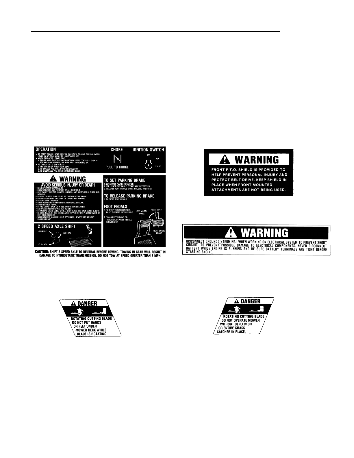
All WARNING, CAUTION and instructional messages on
your tractor and mower should be carefully read and
obeyed. Personal bodily injury can result when these
instructions are not followed. The information is for your
safety and it is important! The safety decals shown below
are on your tractor and mower.
If any of these decals are lost or damaged, replace them
at once. See your local dealer for replacements.
These labels are easily applied and will act as a constant
visual reminder to you, and others who may use the
equipment, to follow the safety instructions necessary for
safe, effective operation.
Decal - Console (20 HP Model shown)
Part No. 1714633 - 18 HP Model
Part No. 1714160 - 20 HP Model
Decal - Danger
Part No. 1704276
Decal - Danger
Part No. 1704277
Decal - PTO Shield
Part No. 1679117
Decal - Battery Warning
Part No. 1679675
Page 10
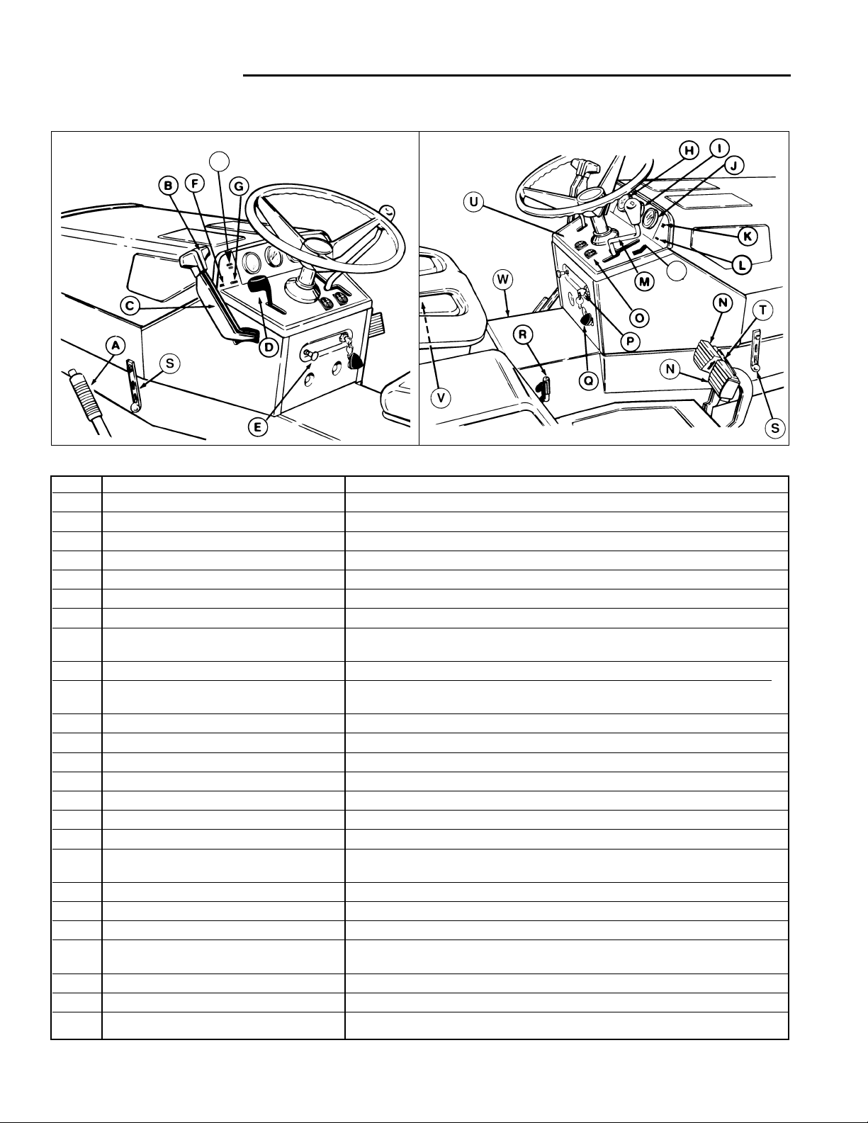
REF NAME FUNCTION
A Mower Height Control Lever Controls mower cutting height.
B Lift Lever, Hydraulic Lifts and lowers attachments.
C Lift Lever, Dual (Optional) Allows use of second hydraulic function.
D Engine Speed Controls engine speed.
E Choke Engages/disengages engine choke for starting.
F Oil Light (Red) Lights up to indicate low oil pressure.
G Neutral Light (Green) Lights up to indicate when ground speed control lever is in neutral
H Voltmeter With engine stopped, shows voltage of battery. With engine running, shows
voltage of charging system. (20 HP models only.)
I Hourmeter Records running time.
J Fuel Gauge On 20 HP models, dash mounted gauge shows amount of fuel in tank. On 18
HP models, the fuel gauge is built into the fuel tank cap.
K Front PTO Light (Red) Lights up to indicate when front PTO is engaged.
L Seat Light (Green) Lights up to indicate when operator is present in seat.
M Ground Speed Control Lever Controls forward and reverse ground speeds.
N Brake Pedals Stops tractor.
O PTO Switch Engages and disengages power to attachments.
P Ignition Switch & Key Starts and stops engine.
Q Parking Brake Holds tractor in stationary position.
R Two-Speed Axle Shift (20 HP) Selects high, neutral or low gear range. Neutral position used to push tractor
manually with engine off.
S Hood Latch One on each side of hood. Pull down and out to release and raise hood.
T Pedal Lock Locks pedals together.
U Rear PTO Switch (Optional) Engages and disengages power to rear attachment.
V Seat Switch Shuts off engine if operator leaves seat when hydrostatic control lever is in
forward or reverse slot.
W Release Valve (18 HP) Allows tractor to be pushed manually with engine off.
X Headlight Switch Turns headlight on or off.
Y Rear PTO Light (Red) (Optional) Lights to indicate when rear PTO is engaged.
6
TRACTOR CONTROLS
Features & Controls
Figure 2. Tractor Controls
*1322
*1323
Left Side
Right Side
X
Y
Page 11
7
Features & Controls
*2374
SAFETY INTERLOCK SYSTEM
Your tractor is equipped with a seat switch safety system
that will automatically shut the engine off when the operator leaves the seat with the ground speed control lever
in gear or with the PTO engaged. Once the engine has
stopped, the electric PTO switch must be turned off after
operator returns to the seat in order to start the engine.
Check operation of dash safety lights. With operator in
seat and ignition switch turned to ON (engine not running):
A. Neutral Indicator Light (G, figure 2) should go on with
ground speed control lever in neutral gate and should
go out when lever is moved to either the forward or
reverse gate.
B. Front PTO Indicator Light (K, figure 2) should go on
and off with operation of PTO switch.
C. Oil Pressure Indicator Light (F, figure 2) should be on
and should go out immediately after engine starts.
D. Operator Seated Indicator Light (L, figure 2) should
go on when operator is present in the seat and
should go off as operator rises out of the seat.
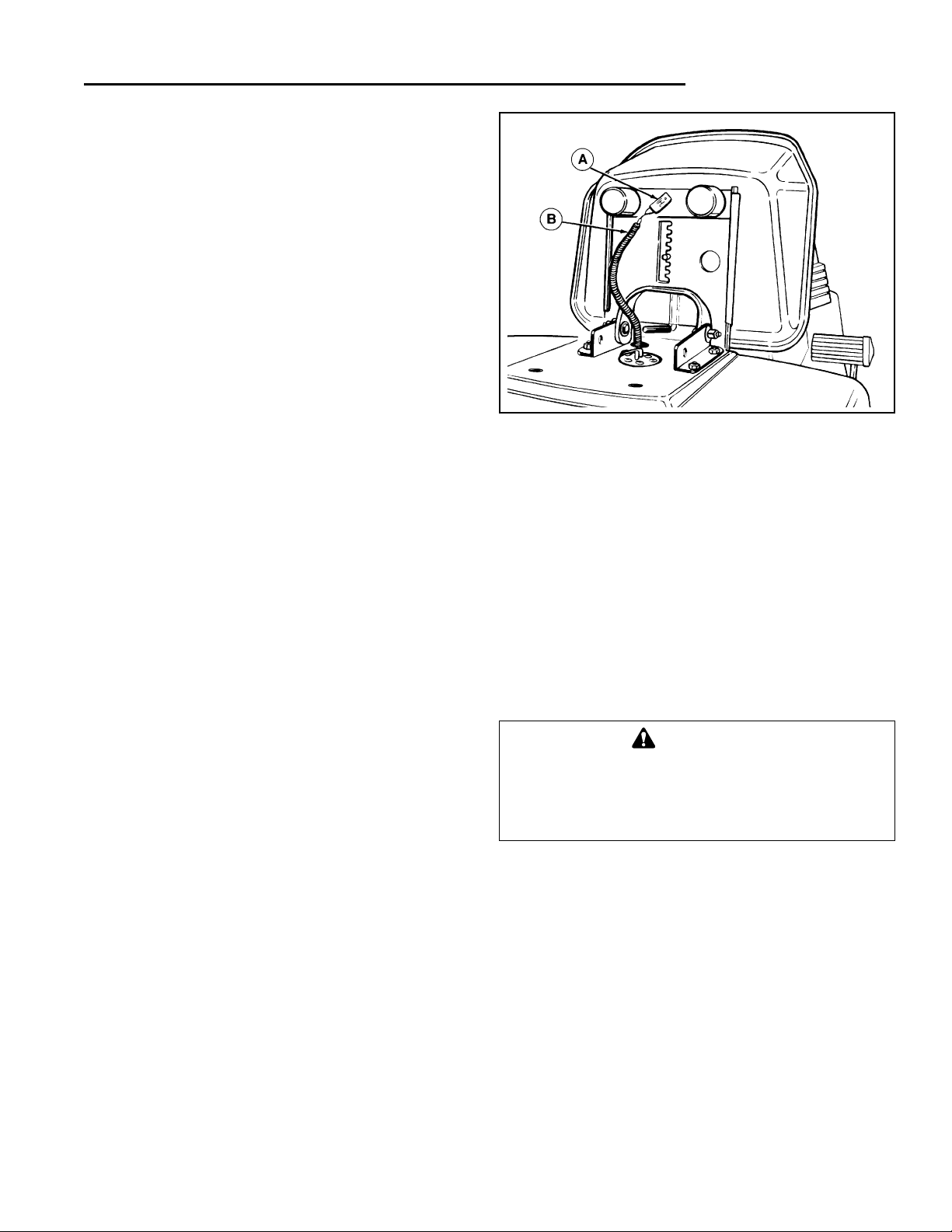
Check the seat switch (A, figure 3) every fall and spring
with the following four tests:
Test 1 - Engine should NOT crank if:
A. seat is not occupied or
B. ground speed control lever out of neutral or
C. PTO switch engaged.
Test 2 - Engine should crank if:
A. seat is occupied and
B. ground speed control lever is in neutral and
C. PTO switch is disengaged.
Test 3 - Engine should shut off if:
A. operator rises off seat with ground speed control
lever in gear
.
B. operator rised off seat with PTO engaged.
NOTE: If operator returns to seat before engine stops,
the engine will re-start and PTO clutch will re-engage.
Test 4 - PTO will disengage if:
A. operator rises off seat with engine running.
NOTE: If operator returns to seat before engine stops,
the engine will re-start and PTO clutch will re-engage.
Figure 3. Seat Switch
A. Switch B. Wiring Harness
WARNING
If the tractor does not pass the test, do not operate tractor. See your authorized dealer. Under no
circumstances should you attempt to defeat the
purpose of the safety system.
Page 12
8
Operation
GENERAL
Before operating this tractor for the first time, the owner
should operate in an open area without mowing, to
become accustomed to the unit. The left side of the
mower can be used to trim close to objects. Be sure to
read all information in the Safety and Operation sections
before attempting to operate this tractor and mower.
MOWER INSTALLATION & REMOVAL
NOTE: Perform mower installation and removal on a
hard, level surface such as a concrete floor.
NOTE: The size and weight of the 60” mower makes it
difficult to slide under tractor. To install or remove 60”
mower, raise front of tractor.
Installation
1. Place mower in low cut position and slide mower
under left side of tractor. Note that the frame is
notched to allow clearance. Turn the wheels fully to
the right and lift hitch arms over wheel as necessary.
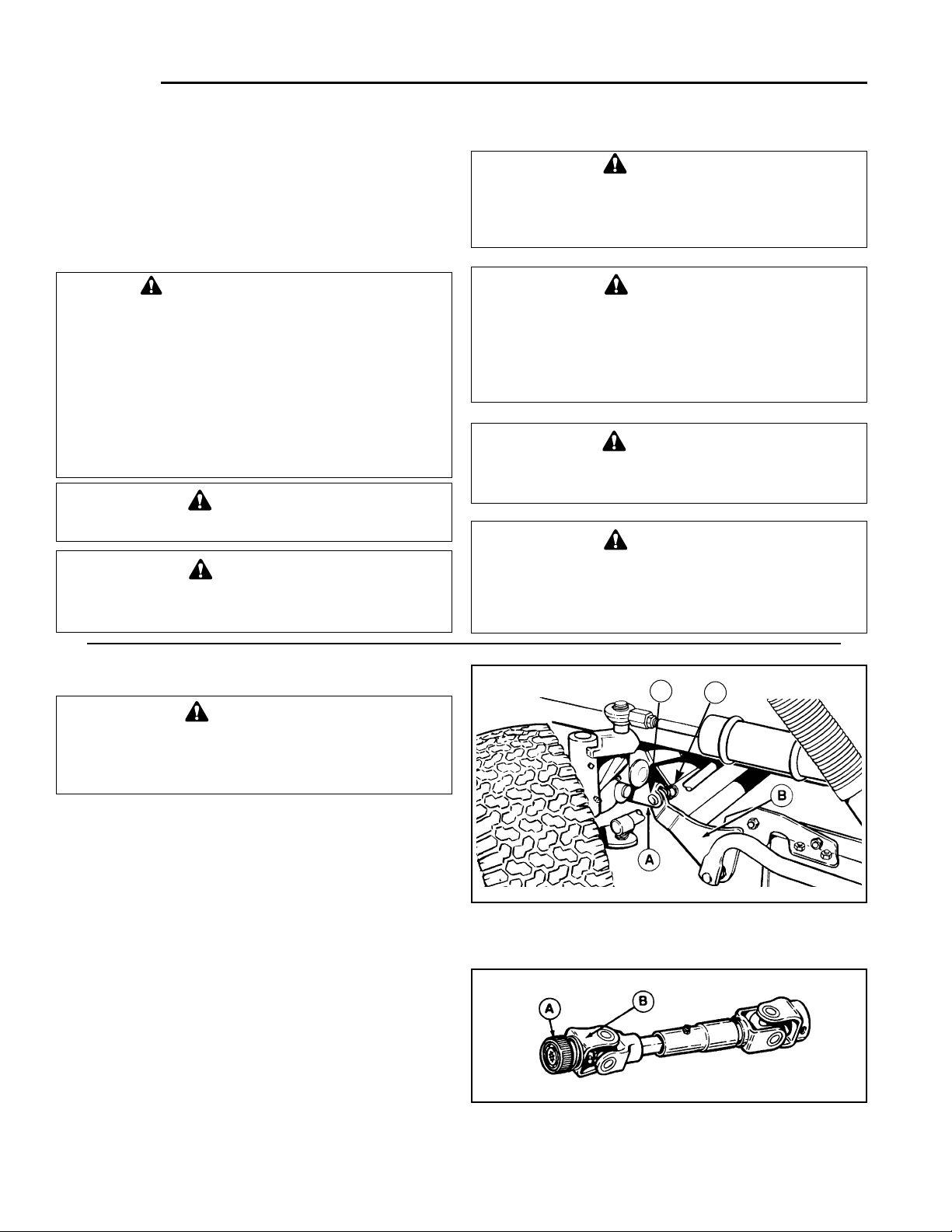
2. For now, align the mower hitch with the tractor hitch
as shown in figure 4. Connecting the hitch comes
later in the installation.
WARNING
Never allow passengers to ride on the unit.
WARNING
To reduce fire hazard, keep the engine and
mower free of grass, leaves and excess grease.
WARNING
Stop engine and remove key. Do not engage PTO
until mower is completely installed or removed
and operator is seated.
WARNING
The interlock safety switches are for your safety.
Do not attempt to bypass them.
CAUTION
Do not attempt to move the ground speed control lever when the parking brake is engaged or
the service brakes are being applied. Equipment
damage will occur.
CAUTION
ON 18 HP MODELS, towing the tractor will cause
transmission damage. Do not use another vehicle to push or pull tractor.
CAUTION
ON 20 HP MODELS, shift 2-speed axle to neutral
before towing. Do not tow faster than 8 mph,
maximum vehicle speed. Towing in gear will
result in damage to the hydrostatic transmission.
Figure 4. Mower Hitch
A. Tractor Hitch C. Pin
B. Mower Hitch Arm D. Hairpin Clip
Figure 5. Mower Drive Shaft
A. Locking Ring B. Coupler
*2528
*1384
WARNING - SLOPE OPERATION
Never operate on slopes greater than 30 percent
(16.7°) which is a rise of three feet vertically in 10 feet
horizontally. When operating on slopes that are
greater than 15 percent (8.5°) but less than 30 percent
use front counterweights and rear wheel weights (see
your dealer). Select slow ground speed before driving
onto slope. In addition to front and rear weights, use
extra caution when operating on slopes with rearmounted grass catcher. Mow UP and DOWN the slope,
never across the face, use caution when changing
directions and DO NOT START OR STOP ON SLOPE.
C
D
Page 13
9
3. The mower drive shaft connects to the tractor drive
shaft by a series of retracting balls located under the
locking ring (A, figure 5). When the locking ring is
released, the balls lock into a groove on the tractor
drive shaft. To connect the drive shaft, proceed as
follows:
A. Place the mower drive shaft barely onto the tractor
drive shaft. Turn the coupler (B, figure 5) to align
the splines.
B. Pull the locking ring (A, figure 5) back, then push
the mower drive shaft onto the tractor drive shaft,
past the groove.
C. Grasp the coupler and pull back. The locking ring
will snap forward into the locked position when the
balls are seated in the groove.
D. Test the connection by pulling back on the coupler.
You should not be able to pull it off.
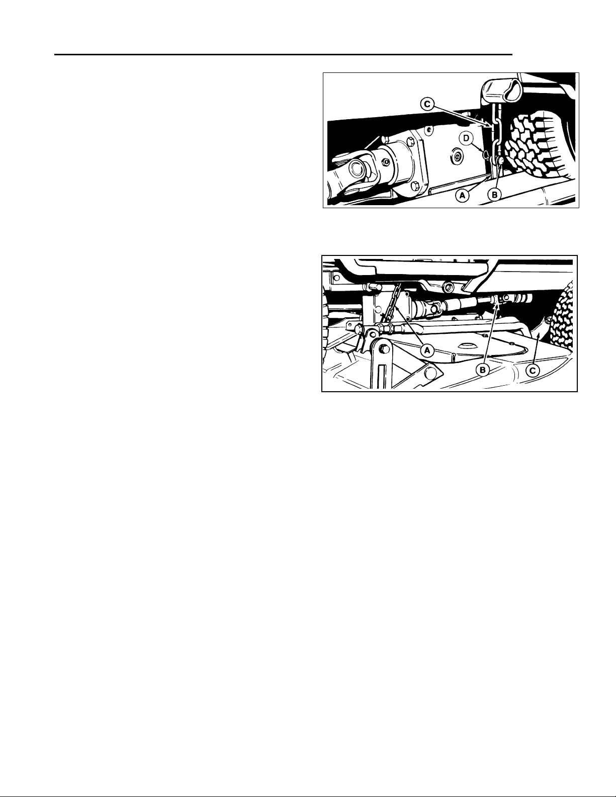
4. Raise mower to mid-cut position. See figure 6. Hook
the chains (C) to the clevis (A) on each side of the
gear box. Insert pin (B) through clevis and chain, then
install hairpin clip (D) in pin. Hairpin clip should be
installed towards the inside as shown.
NOTE: When connecting mower deck to tractor, use 3
links of chain.
5. Start the engine and turn the front wheels straight
ahead. Using the hydraulic lift lever (B, figure 2),
raise the mower to full transport position, then shut
off the engine.
6. Use the following procedure to connect the hitch
arms (B, figure 4).
A. Place the mower height control lever (A, figure 2) in
the second notch from high cut position. This
should align the hitch.
B. Use your right hand to apply pressure on the
mower height control quadrant brace in order to
maneuver mower hitch arm(B, figure 4) into the
tractor hitch (A, figure 4). When aligned, use your
left hand to insert pins through mower hitch arms
and tractor hitch. Insert pins so the hole is vertical
to aid in hairpin clip installation. Install hairpin clips
in both pins.
NOTE: Align holes by applying rearward pressure on the
mower height control lever.
7. Figure 7 shows mower installed, as viewed from the
right side.
**1384
Figure 7. Mower Installed -Viewed From Right Side
A. Chain C. Hitch
B. Drive Shaft
Operation
Figure 6. Lift Chains
A. Clevis C. Chain
B. Pin D. Hairpin clip
*1681
Removal
1. Use the mower height control lever (A, figure 2) and
place mower in the 2nd notch from the high cut position.
2. With the engine running, use the hydraulic lift lever
(B, figure 2) to raise the mower to the transport position, then shut off the engine and remove the key to
prevent accidental starting.
3. Remove the pins and clips from hitch (figure 5). Push
back on height control lever to aid removal of pins
and to maneuver mower.
4. Move the lift lever (B, figure 2) forward to lower the
mower.
5. Disconnect the drive shaft by pulling back on the
locking ring and pulling coupler toward the rear.
6. With mower in high cut position, disconnect the
chains (figure 7).
7. Place mower in low cut position and turn wheels fully
right. Mower can be removed. Tractor frame is
notched for gear box clearance.
Page 14
10
CHECKS BEFORE STARTING
1. Make sure you have proper wheel or counterweights
if required. See SLOPE OPERATION in the Safety
Rules section. Make sure any slopes are within
required limits.
2. Check that crankcase is filled to full mark on dipstick.
See the engine Operator’s Manual for instructions
and oil recommendations.
3. Make sure all nuts, bolts, screws and pins are in
place and tight.
4. Make sure you can reach all controls from operator’s
positions. If not, see SEAT ADJUSTMENT.
5. Fill the gasoline tank with fresh gasoline. Fill to bottom of filler neck to avoid spillage and overflow. DO
NOT mix oil with gasoline. Refer to engine manual for
gasoline recommendations.
STARTING THE ENGINE
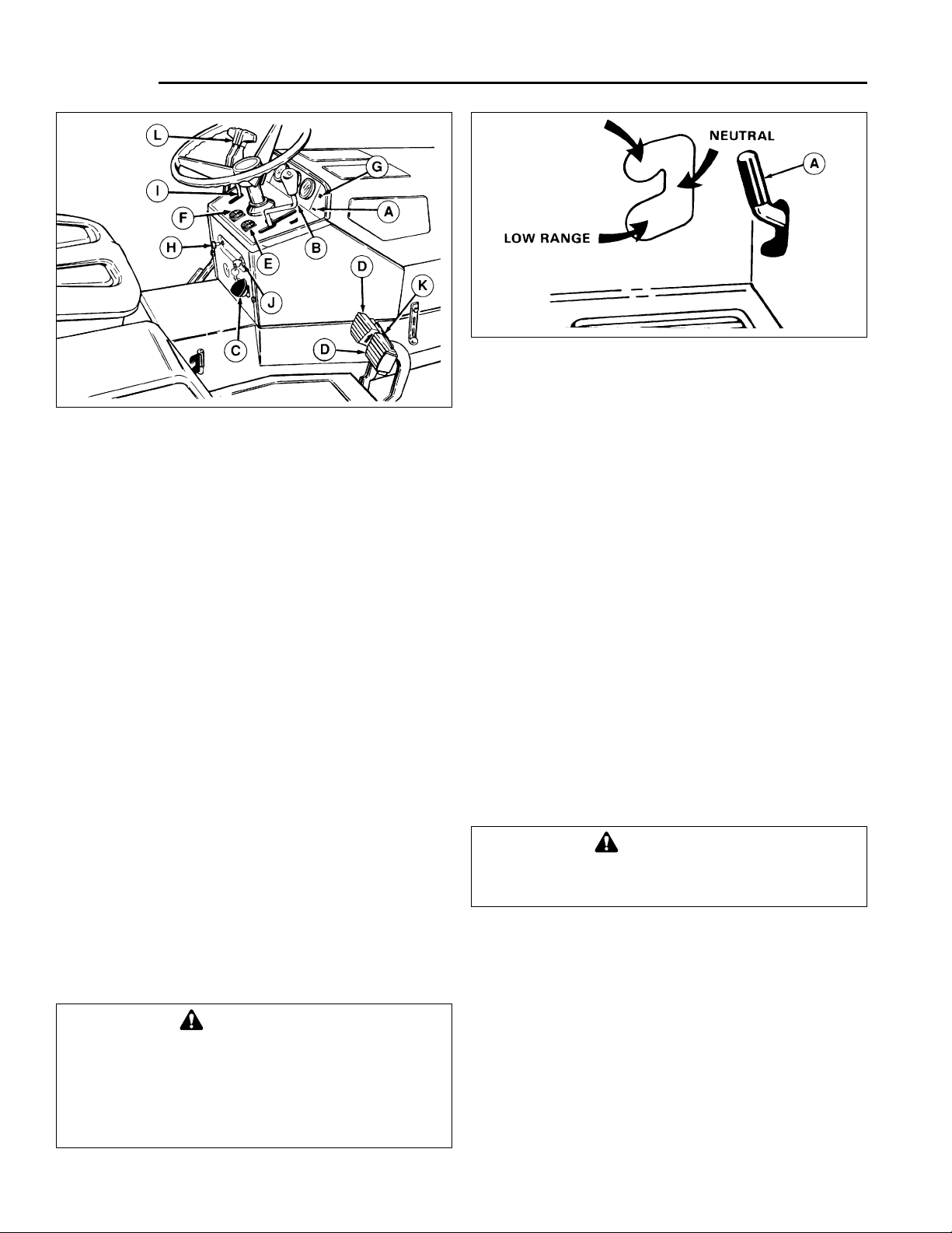
Refer to figure 8.
1. Operator must be seated. Seat light (A) will light up
when key is turned on.
2. Place ground speed control lever (B) in neutral. Set
parking brake. To set, lock brake pedals together
with the pedal lock (K), depress pedals, pull parking
brake knob (C) out, then release pedals.
3. PTO switch(es) (E & F) must be in OFF position.
PTO light (G) will not be on.
4. On a cold engine, pull out choke knob (H). On a
warm engine, push choke knob in.
5. Place throttle lever (I) midway between slow and fast
(Start/Stop position).
6. Turn key (J) to start engine. Push choke in as engine
warms up.
7. Allow engine to warm up for a couple of minutes
before applying load. Do not idle engine for prolonged periods or carbon buildup may occur.
SELECTING AXLE SPEED RANGE
(20 HP Models Only)
1. The axle shift lever (figure 9) is designed to fit very
flush with the rear foot deck panel to avoid accidental
shifting. Select low speed (bottom position) for heavy
work or high speed (upper position) for traveling to
work areas.
2. Rock the tractor back and forth slightly to make
shifting easier.
Operation
WARNING
Gasoline is highly flammable and must be handled with care. Never fill the tank when the
engine is still hot from recent operation. Do not
allow open flame, smoking or matches in the
area. Avoid over-filling and wipe up any spills.
Figure 8. Tractor Controls
A. Seat Light G. Front PTO Light
B. Ground Speed H. Choke Knob
Control Lever I. Throttle Lever
C. Parking Brake Knob J. Ignition Switch Key
D. Brake Pedals K. Brake Pedal Lock
E. Front PTO Switch L. Lift Lever, Hydraulic
F. Rear PTO Switch
(Optional)
WARNING
Make sure desired direction of travel is clear of
objects, people and animals.
*1323
Figure 9. Two-Speed Axle Shift (20 HP Models)
A. Axle Shift Lever
Page 15

4. To set parking brake depress brake pedals, pull parking brake knob (C) out, then release pedals.
5. Push hydraulic lift lever forward to lower attachment.
6. Turn ignition off and remove key to prevent unauthorized use.
PUSHING THE TRACTOR BY HAND
18 HP Models
Release lever is located just ahead of left rear fender.
1. To actuate release lever, push lever down firmly and
hold for a few seconds before releasing.
2. Push tractor by hand with the engine off.
20 HP Models
1. Set the axle shift lever (figure 9) to the neutral position.
2. Push tractor by hand with the engine off.
3. Make sure lever is firmly seated all the way in the low
range or high range slot before operating tractor.
OPERATION
Refer to figure 8.
1. Press pedals (D) to release parking brake.
2. Move ground speed control lever (B) to forward or
reverse to start into motion. The farther lever is
moved, the faster the ground speed. Place throttle
lever in forward (fast) position.
3. Push the hydraulic control lever (L) forward to lower
the attachment. Pull lever back to raise the attachment.
4. Use the PTO switch(es) (E & F) to engage or disengage the attachment. Lift switch to engage.
5. The brake pedals can be used to help make sharp
turns. Press the right pedal to aid a right-hand turn;
press the left pedal to aid in making a left-hand turn.
When driving at high speed, such as traveling to a
work site, keep the brake pedals locked together.
Forward ground speed is reduced by 1/2 when
depressing one pedal.
STOPPING THE TRACTOR
Refer to figure 8.
1. Move ground speed control lever (B) to neutral and
depress brake pedals.
2. Switch PTO to off.
3. Move throttle midway between slow and fast position
before shutting off engine.
11
Operation
WARNING
Before leaving operator’s position for any reason, engage the parking brake, disengage the
PTO(s), stop the engine and remove the key.
WARNING
Do not tow the tractor. Damage will result to the
transmission/transaxle.
Page 16

12
Mowing Patterns & Tips
For the first use of the mower, choose a smooth level
area. Cut long straight strips overlapping slightly.
The size and type of area to be mowed determines the
best mowing pattern to use. Obstructions such as trees,
fences and buildings must also be considered. Where
possible, make one or two passes in a counterclockwise
direction around the outside of the area to keep the cut
grass off fences and walks. The remainder of the mowing should be done in a clockwise direction so the clippings are dispersed on the cut area.
Keep in mind the following lawn care and mowing tips:
• Too much maintenance is as detrimental to your lawn
as neglect.
• Mow when grass is 3-5 inches tall. Don’t cut shorter
than 2 to 2-1/2 inches. Cut only the top one-third of the
grass blade. Cutting below this level can lead to thatch
problems. Your mower has a cutting height adjustment
that can help you maintain a proper length.
• For extremely tall grass, set the cutting height at
maximum for the first pass, and then reset to the
desired height and mow again.
• Mow often. Short clippings of an inch or less decompose more quickly than longer blades.
• Keep the blades on your mower sharp for finer clippings.
• Let grass grow a bit longer when it is hot to reduce
heat build-up and protect grass from heat damage.
• Use slow-release fertilizer for slow, even growth.
• Don’t cover grass surface with a heavy layer of clippings. Consider using a grass collection system and
starting a compost pile.
• Aerate lawn in spring, consider renting an aerator
which removes cores of soil from the lawn. This
increases the speed of clipping decomposition and
deep root growth by opening up the soil and permitting
greater movement of water, fertilizer and air.
• Don’t over-water. Too much water can encourage
disease development.
• Mow when the grass is dry, preferably in the late
afternoon when the temperatures are cooler.
• Where possible, change patterns occasionally to
eliminate matting, graining or a corrugated appearance.
• For wet grasses, grasses prone to wheel tracking and
for collecting clippings:
a. Use sharp blades.
b. Raise deck 1/4” higher in front than in rear.
c. Run at maximum engine speed but slow ground
speed.
d. Clean deck of built-up material/caked-on grass.
e. Check for free movement of mower idler pulley.
• For dry conditions where grass blow-out is a problem:
a. Use sharp blades.
b. Raise deck so the front is even with, or 1/8” lower
than, rear.
c. Use 3/4 engine speed.
d. Clean deck of built-up material/caked-on grass.
Page 17
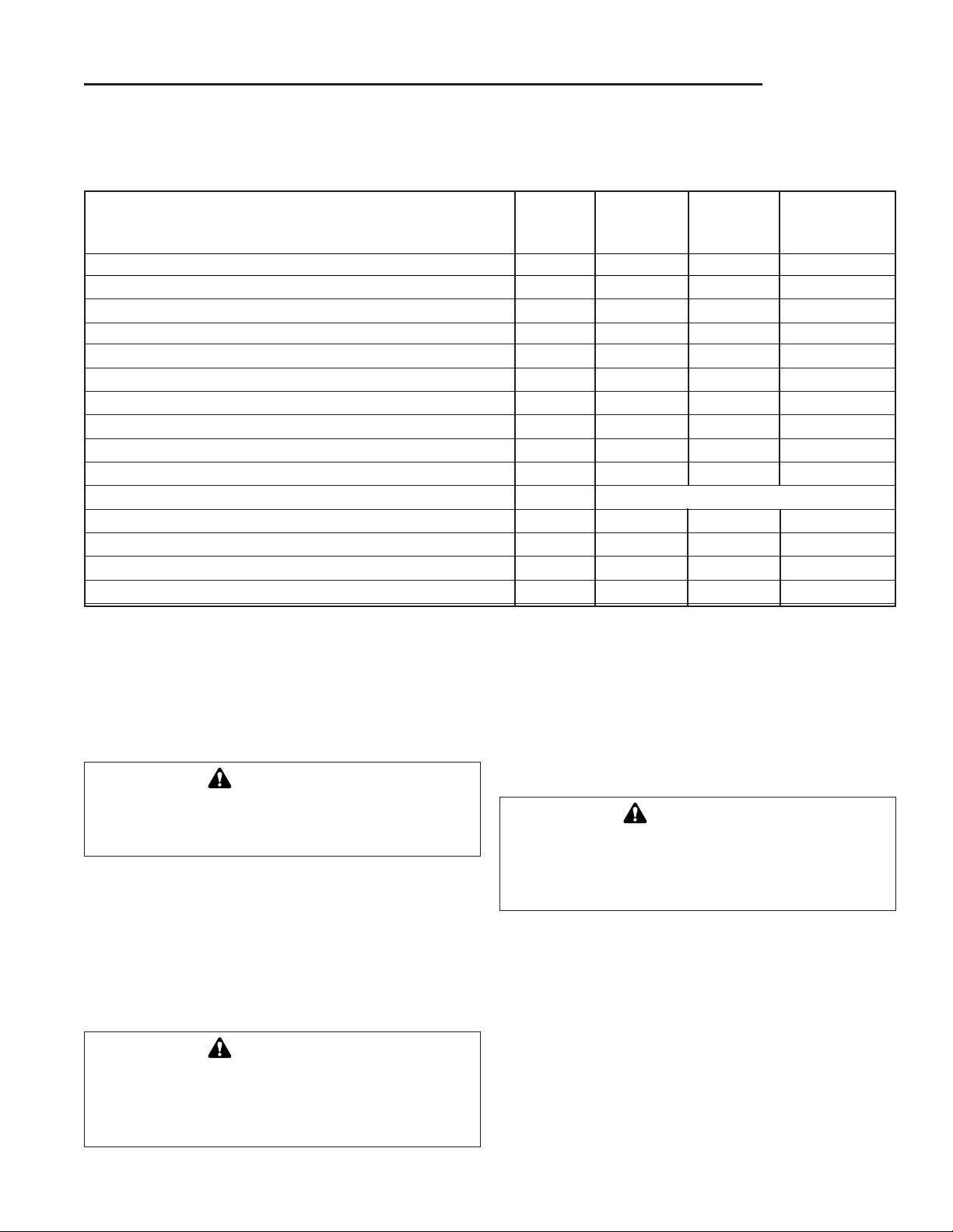
See Every Every Every
Safety Items Page 5 Hours 25 Hours 100 Hours
*Or Yearly
Check safety interlock system. 7 ●
Check tractor brakes. 24 ●
Normal Care Items
Check tractor & mower for loose hardware. – ●
Clean heat exchanger. - ●
Clean hydrostatic cooling fins with compressed air. - ●
Check tires. 13 ●
Lubricate tractor and mower. 14 ●
Oil Pivot points. 15 ●
Check transmission fluid. 15 ●
Change transmission fluid & filter. 16 Trans. service only or every 400 hours.
Check and clean battery. 16 ●
Clean, sharpen and balance blades. 17 ●
Clean and repack front wheel bearings. - ●
See engine manual for engine care & maintenance.
* or as needed.
13
RAISING THE HOOD
To gain access to the engine compartment, release the
rubber strap (S, figure 2) on each side of the hood and
raise the hood.
CHECKING/ADDING GASOLINE
Check the gas gauge/cap to be sure there is enough
gasoline to complete the job. To add gasoline, remove
the gas gauge/cap. Do not overfill. Leave room in the
tank for fuel expansion. Refer to your engine manual for
gasoline recommendations. Install and hand tighten the
gas gauge/cap.
CHECKING TIRE PRESSURE
Front tire pressure should be 12 to 15 psi (82 to 103 kPa).
Rear tire pressure should be 6 to 8 psi (41 to 55 kPa).
CHECKING FUEL FILTER
The fuel filter is located in fuel line between fuel tank and
carburetor. If filter is dirty or clogged, replace as follows.
Place a container below filter to catch spilled gasoline.
1. Using a pliers, open and slide hose clamps from fuel
filter.
2. Remove hoses from filter.
3. Install new filter in proper flow direction in fuel line.
Secure with hose clamps. See warning at beginning
of procedure.
Normal Care
SCHEDULE
The following schedule should be followed for normal care of your tractor and mower. You will need to keep a record
of your operating time.
CAUTION
Do not run the engine with the hood raised.
Engine heat will cause damage to the headlight
bezel and hood.
CAUTION
Never use gasoline containing METHANOL, gasohol containing more than 10% ethanol, gasoline
additives, premium gasoline, or white gas because
engine/fuel system damage could result.
WARNING
Do not remove fuel filter when engine is hot, as
spilled gasoline may ignite. DO NOT spread hose
clamps further than necessary. Ensure clamps
grip hoses firmly over filter after installation.
Page 18
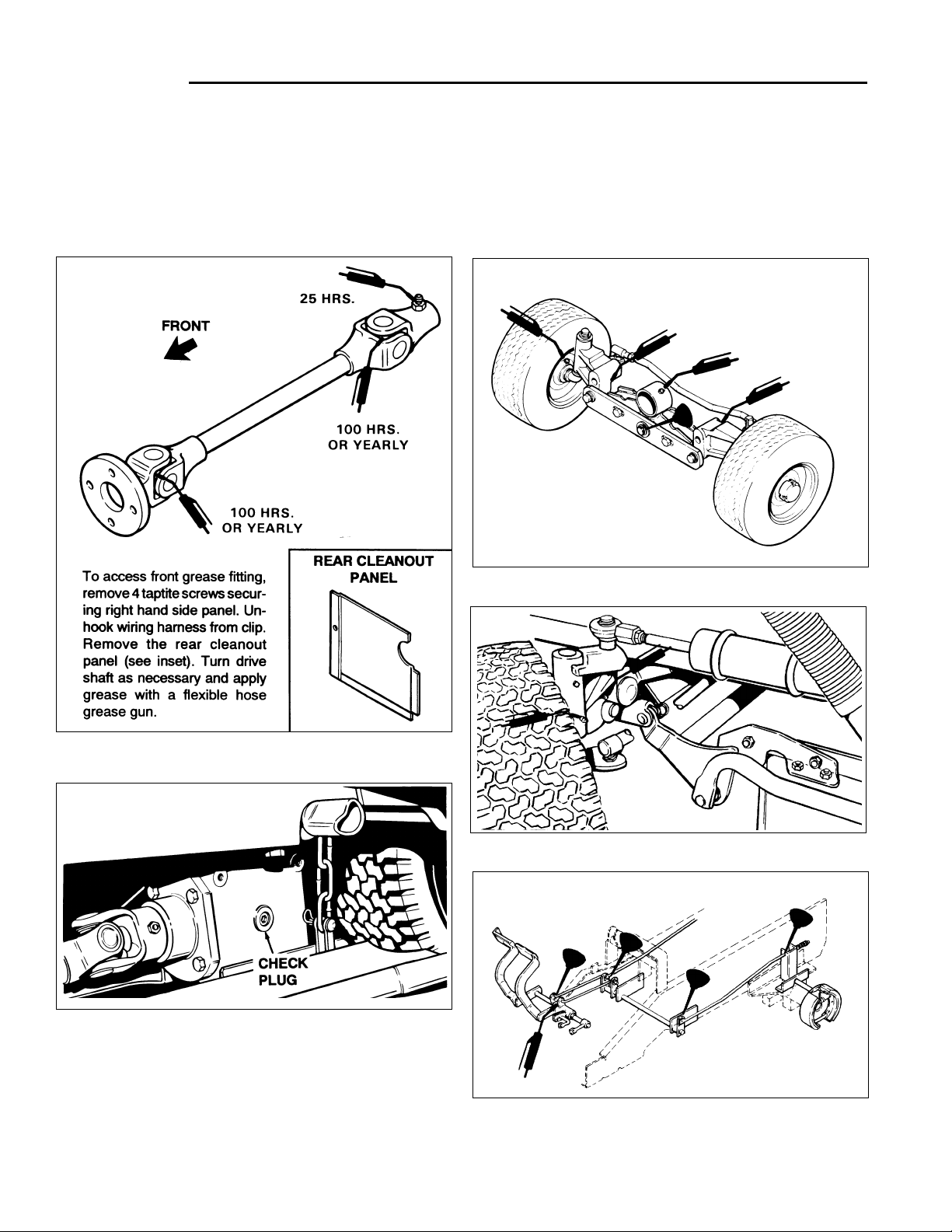
14
LUBRICATION
Tractor & Mower Lubrication
Lubricate the tractor and mower as shown in figures 10 -
18. When a grease gun is shown, wipe the fitting clean,
apply two or three shots of lithium base automotive
Normal Care
*1873 *1875
Figure 11. Gear Box Fluid Check
Figure 10. Engine Drive Shaft
Figure 12. Center Front Axle and Wheels
*1681
Figure 13. Front Axle and Spindle
*2528
Figure 14. Foot Pedal Assembly
*1874
grease, and wipe off excess grease. When an oil can is
shown, wipe the area clean, apply a few drops of oil
(SAE 30), then wipe up drips or spills.
Page 19
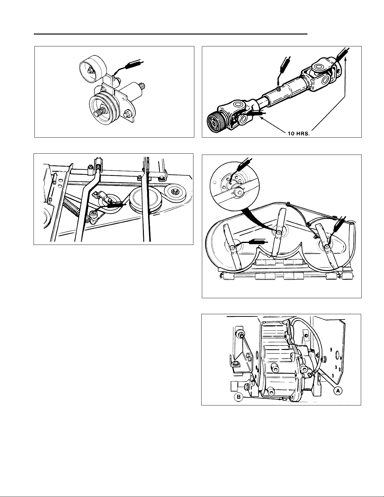
15
Normal Care
Figure 16. Mower Belt Idler (Grease fitting located
under rubber plug on arbor cover)
*1684
Figure 18. Mower Arbor
*1606
Figure 17. Mower Drive Shaft
*1384
Figure 19. Transmission Fluid Check
A. Hydraulic Tube B. Drain Plug
*1648
Figure 15. PTO Idler Assembly
*1872
Checking Mower Gear Box Fluid
1. See figure 11. Remove check plug on left-hand side
of gear box.
2. Fluid should be at bottom of hole when mower is
level. Add SAE 85W-90 gear oil as necessary.
3. Install check plug.
Oil Pivot Points
A few drops of engine oil should be placed on the pivot
points and moving parts of the tractor and mower. Keep
oil off belts and pulleys to prevent belt damage. Place oil
at all points where metal parts rub together, such as rods
and rod guides, levers, etc. Oil all shaft splines.
CHECKING TRANSMISSION FLUID
Check with the engine off. See figure 19. fluid should be
visible in tube at rear of tractor with rear access panel
removed. Fluid should not extend more than 1” above fitting.
To add fluid, raise hood and add at fill tube (D, figure 20).
Fill with Type F transmission fluid.
Page 20
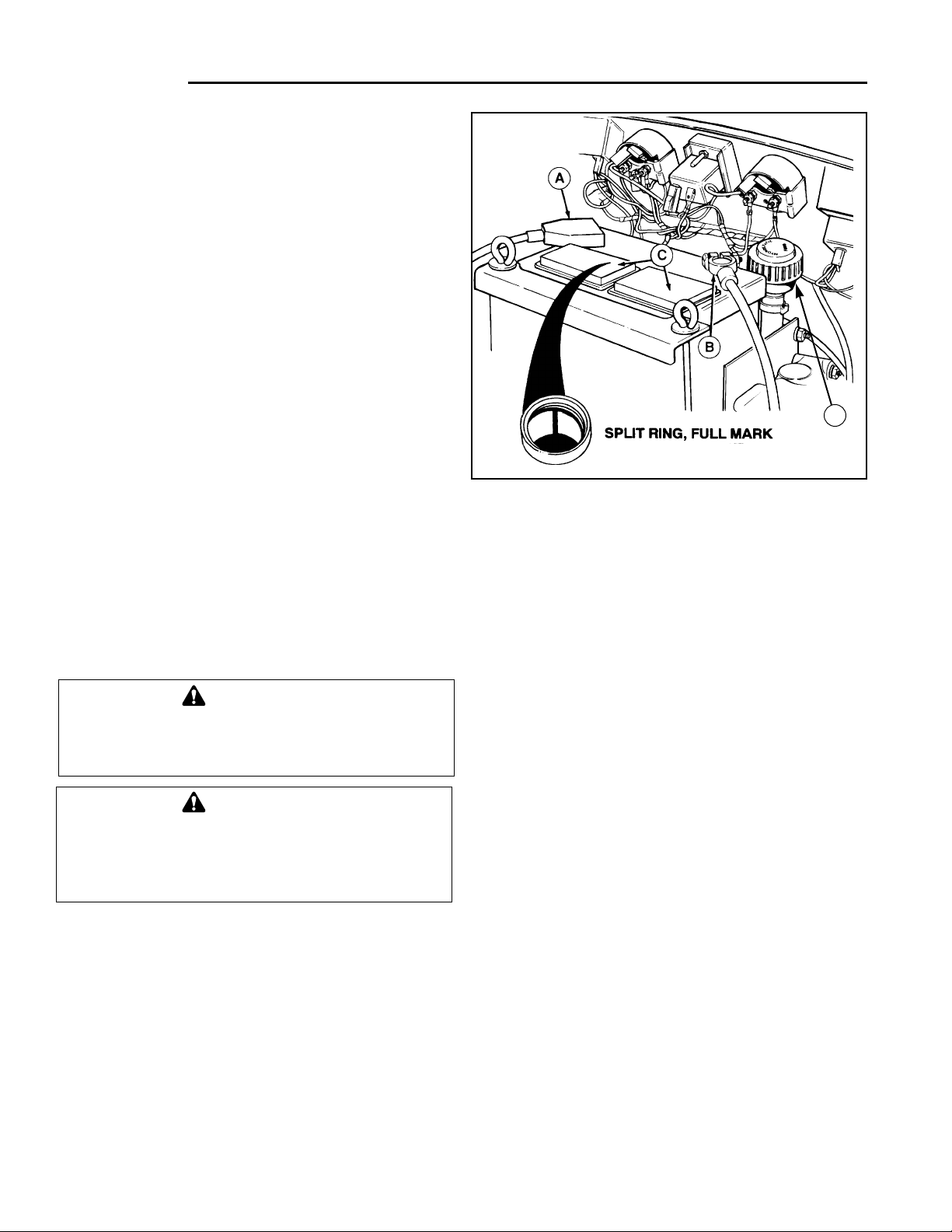
16
Cleaning the Battery and Cables
1. Disconnect the cables from the battery, negative
cable first (B, figure 22).
2. Remove the battery clamp, then remove the battery.
3. Scrub the battery, cables and battery compartment
with baking soda and water. 4. Clean the battery terminals and cable clamps with a wire brush
and battery post terminal cleaner.
5. Reinstall battery and clamp.
6. Connect cables, positive cable first.
7. Coat cable clamps and terminals with grease or
petroleum jelly.
*2519
Figure 20. Battery Compartment
A. Positive Battery Terminal C. Filler Caps
B. Negative Battery Terminal D. Transmission Fill
Tube
Normal Care
CHANGING TRANSMISSION FLUID
& FILTER
Transmission fluid and filter should be changed only
when performing repair work or if fluid has become discolored from overheating or contamination. Perform fluid
change every 400 hours of operation if no other transmission service has been done.
Replace the transmission filter whenever changing transmission fluid. Make sure filter base and surrounding area
is absolutely clean before removing old filter.
1. Drain hydrostatic system by removing drain plug (B,
figure 19). Drain fluid into a suitable container.
2. Clean base and replace filter using an appropriate filter wrench. Reinstall drain plug.
3. Add Type F transmission fluid. Capacity is 6 quarts
(5.7 L).
4. Run tractor for several minutes until transmission is
warm and check fluid level in tube (A, figure 19).
BATTERY MAINTENANCE
Checking the Battery Fluid
1. Raise the hood.
2. Remove battery filler cap. Fluid must be even with split
ring full mark. If not, add distilled water.
3. Reinstall filler cap.
WARNING
Be careful when handling the battery. Avoid
spilling electrolyte. Keep flames and sparks
away from the battery.
WARNING
When removing or installing battery cables, disconnect the negative cable FIRST and reconnect
it LAST. If not done in this order, the positive terminal can be shorted to the frame by a tool.
D
Page 21
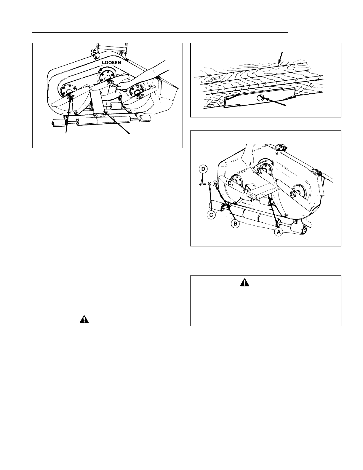
SERVICING THE MOWER BLADES
1. Remove mower from the tractor.
2. Blades should be sharp and free of nicks and dents.
If not, sharpen blades as described in following steps.
3. To remove blade for sharpening, use wooden block
to hold blade while removing the blade mounting capscrew (figure 21).
4. Use a file to sharpen blade to fine edge. Remove all
nicks and dents in blade edge. If blade is severely
damaged, it should be replaced.
5. Balance the blade as shown in figure 22. Center the
blades’ hole on a nail lubricated with a drop of oil. A
balanced blade will remain level.
6. Reinstall each blade with the tabs pointing up toward
deck as shown in figure 23. Secure with a capscrew
(D), cup washer (C) and spline washer (B). Use a
wooden block to prevent blade rotation and torque
capscrews to 50-70 ft.lbs. (67-95 Nm.).
17
Normal Care
*1687
Figure 21. Removing The Blade
Figure 22 Balancing The Blade
Figure 23. Installing The Blade
A. Wooden Block C. Cup Washer
B. Spline Washer D. Capscrew
*169
WARNING
For your personal safety, blade mounting capscrews must each be installed with a cup washer
and spline washer, then securely tightened.
Torque blade mounting capscrew to 50-70 ft.lbs.
(67-95 N.m.)
WARNING
For your personal safety, do not handle the
sharp mower blades with bare hands. Careless
or improper handling of blades may result in
serious injury.
*1688
Blade Mounting
Capscrew
Wooden Block
Loosen
Thin Finishing Nail
Workbench
Tighten
Page 22

18
Storage
TEMPORARY STORAGE
(30 Days Or Less)
Remember, the fuel tank will still contain some gasoline,
so never store the tractor indoors or in any other area
where fuel vapor could travel to any ignition source. Fuel
vapor is also toxic if inhaled, so never store the tractor in
any structure used for human or animal habitation.
Here is a checklist of things to do when storing your tractor temporarily or in between uses:
• Keep the tractor in an area away from where children
may come into contact with it. If there’s any chance of
unauthorized use, remove the spark plug (s) and put
in a safe place. Be sure the spark plug opening is
protected from foreign objects with a suitable cover.
• If the tractor can’t be stored on a reasonable level
surface, chock the wheels.
• Clean all grass and dirt from the mower.
NOTE: If storing your tractor between winter snow
removal jobs in a cold area, we suggest that you fill the
fuel tank at the completion of each job to prevent water
condensation in the fuel tank. Wait for engine to cool
before filling tank.
LONG TERM STORAGE
(Longer Than 30 Days)
Before you store your tractor for the off-season, read the
Maintenance and Storage instructions in the Safety
Rules section, then perform the following steps:
1. Drain crankcase oil while engine is hot and refill with
a grade of oil that will be required when tractor is
used again.
2. Prepare the mower deck for storage as follows:
a. Remove mower deck from the tractor.
b. Clean underside of mower deck.
c. Coat all bare metal surfaces with paint or light coat
of oil to prevent rusting.
3. Clean external surfaces and engine.
4. Prepare engine for storage. See engine owner’s
manual.
5. Clean any dirt or grass from cylinder head cooling
fins,engine housing and air cleaner element.
6. Cover air cleaner and exhaust outlet tightly with plastic or other waterproof material to keep out moisture,
dirt and insects.
7. Completely grease and oil tractor as outlined in the
Normal Care section.
8. Clean up tractor and apply paint or rust preventative
to any areas where paint is chipped or damaged.
9. Be sure the battery is filled to the proper level with
water and is fully charged. Battery life will be
increased if it is removed, put in a cool, dry place and
fully charged about once a month. If battery is left in
tractor, disconnect the negative cable.
10.Drain fuel system completely or add a gasoline stabilizer to the fuel system. If you have chosen to use a
fuel stabilizer and have not drained the fuel system,
follow all safety instructions and storage precautions
in this manual to prevent the possibility of fire from
the ignition of gasoline fumes. Remember, gasoline
fumes can travel to distant sources of ignition and
ignite, causing risk of explosion and fire.
NOTE: Gasoline, if permitted to stand unused for extended periods (30 days or more), may develop gummy
deposits which can adversely affect the engine carburetor and cause engine malfunction. To avoid this condition, add a gasoline stabilizer to the fuel tank or drain all
fuel from the system before placing unit in storage.
WARNING
Never store the tractor, with gasoline in engine or fuel tank, in a heated shelter or in enclosed, poorly
ventilated enclosures. Gasoline fumes may reach an open flame, spark or pilot light (such as a furnace,
water heater, clothes dryer, etc.) and cause an explosion.
Handle gasoline carefully. It is highly flammable and careless use could result in serious fire damage to
your person or property.
Drain fuel into an approved container outdoors away from open flame or sparks.
Page 23

19
11.Transport the tractor to a suitable, dry, indoor location. If the tractor is to be stored 6 months or longer,
block the tractor up off the wheels to relieve weight
and also to keep the tires off a damp floor. Protect
tires from prolonged exposure to direct sunlight.
STARTING AFTER
LONG TERM STORAGE
Before starting the tractor after it has been stored for a
long period of time, perform the following steps.
1. Remove the blocks from under the tractor.
2. Install the battery if it was removed.
3. Unplug the exhaust outlet and air cleaner.
4. Fill the fuel tank with fresh gasoline. See engine
manual for recommendations.
5. Check crankcase oil level and add proper oil if
necessary.
6. Inflate tires to proper pressure. Check fluid levels.
7. Start the engine and let it run slowly. DO NOT run at
high speed immediately after starting. Be sure to run
engine only outdoors or in well ventilated area.
Storage
Page 24

GENERAL
This section of the manual provides troubleshooting and
repair instructions for the more common and easily
corrected problems. For other problems, it is recommended that you contact your dealer.Locate the problem
that best describes the trouble that you have encountered. Check the possible causes one at a time, in the
order that they are listed.
TROUBLESHOOTING THE TRACTOR
Engine will not turnover or start.
1. Ground speed control lever not in neutral-start position.
Shift into neutral.
2. PTO (electric clutch) switch(es) in ON position. Place in
OFF position.
3. Out of fuel. If engine is hot, allow it to cool, then refill the
fuel tank.
4. Engine flooded. Push choke knob in (twin cylinder models) or move throttle control out of CHOKE position.
5. Circuit breaker tripped. Wait one minute for automatic
reset. Replace if defective (see your dealer).
6. Battery terminals require cleaning. See Normal Care
section.
7. Battery discharged or dead. Recharge or replace.
8. Wiring loose or broken. Visually check wiring & replace
broken or frayed wires. Tighten loose connections.
9. Solenoid or starter motor faulty. Repair or replace.
10.Safety interlock switch or module faulty. Replace if
needed (see your dealer.)
11.Operator not in seat.
Engine cranks but will not start.
1. Out of gasoline.
2. Engine flooded. Push in choke and attempt to start.
Hold throttle wide open.
3. Crankcase oil too heavy. See engine manual.
4. Water in gasoline or gasoline is stale. Drain and fill
with fresh gasoline.
5. Faulty engine electrical or fuel system. See engine
manual or your dealer.
Engine starts hard or runs poorly.
1. Fuel mixture too rich. Clean air filter. Check choke
adjustment (engine speed control). See engine manual.
2. Carburetor adjusted incorrectly. See engine manual.
3. Spark plug(s) faulty, fouled, or incorrectly gapped.
Clean and gap or replace. See engine manual.
4. In hot weather, fuel may evaporate from carburetor
when engine is shut off, causing engine to run rough
for a few minutes after starting. Do not shut off; allow
engine to clear itself.
5. Start engine with throttle midway between slow and
fast.
Engine knocks.
1. Low oil level. Check/add oil as required.
2. Using wrong grade oil. See engine manual.
3. Wrong grade of gasoline. Use fresh, regular grade of
gasoline.
Excessive oil consumption.
1. Engine running too hot. Clean engine fins, blower
screen and air cleaner.
2. Using wrong weight oil. See engine manual.
3. Too much oil in crankcase. Drain excessive oil.
Engine exhaust is black.
1. Dirty air filter. Clean air filter. See engine manual.
2. Check engine speed control adjustment (choke).
See engine manual.
3. Carburetor adjustment is incorrect. See engine manual or your dealer.
Tractor creeps in neutral.
1. Tractor creeps forward or backward with ground
speed control lever in neutral gate. See your dealer
for neutral adjustment.
Engine runs, but tractor will not drive or
lacks power .
1. Ground speed control lever in neutral. Shift in forward
or reverse.
2. On 20 HP models, two-speed axle shift in neutral.
Place in either low or high range.
3. Transmission oil cold. Allow 3 minutes for warm-up.
20
Troubleshooting & Repair
WARNING
To avoid serious injury, perform maintenance on
the tractor or mower only when the engine is
stopped and the parking brake engaged. Always
remove the ignition key, disconnect spark plug
wire and fasten away from the plug before beginning the maintenance, to prevent accidental
starting of the engine.
Page 25

21
4. Transmission fluid low. Add as required. Check for
leaks.
5. Transmission oil too hot. Check transmission cooling
fins for grass or clippings and clean with brush or
compressed air. Do not use water.
6. Belt is broken. See Drive Belt Replacement.
7. Brake is not fully released. See Brake Adjustment.
Brake will not hold.
1. Brake is incorrectly adjusted. See Brake Adjustment.
2. Brake lining worn. Replace.
Engine backfires when shut off.
1. Engine backfire may occur when shut off hot. To
reduce backfiring, move throttle lever midway
between fast and slow for a couple seconds before
shut off.
2. Carburetor solenoid not functioning. See your dealer.
TROUBLESHOOTING THE MOWER
Mower will not raise.
1. Lift mechanism not attached or broken. Attach or
replace as necessary.
2. Hydraulic lift system faulty. See your dealer.
Mower cut is uneven.
1. Mower not leveled properly. See Mower Adjustment.
2. Tractor tires not inflated equally or properly. See
Normal Care.
3. Missing pin on mower hitch. Install pin.
Mower cut is rough looking.
1. Engine speed too slow. Set for full throttle speed.
2. Ground speed too fast. Set ground speed control
lever at a slower ground speed.
3. Blades dull and require sharpening. See Servicing the
Mower Blades.
4. Mower arbor belt slipping. Belt oily or worn. Clean or
replace belt as necessary.
5. Mower idler pulley pivot sticking. Check/lubricate as
necessary. See Normal Care.
5. Check PTO (Electric Clutch) Adjustment. Clutch may
need to be adjusted.
6. Blades not properly fastened to arbors or bent. See
Servicing the Mower Blades.
Engine stalls easily with mower engaged.
1. Engine speed too slow. Set for 3/4 to full throttle.
2. Ground speed too fast.
3. Engine cold. Allow warm-up period.
4. Cutting height set too low when mowing tall grass.
Cut tall grass at maximum cutting height during first
pass.
5. Discharge chute jamming with cut grass. Cut grass
with discharge pointing toward previously cut area.
Excessive mower vibration.
1. Blade mounting screws are loose. Tighten to 50-70
ft.lbs. (74 Nm.).
2. Mower blades, arbors, or pulleys are bent. Check and
replace as necessary.
3. Mower blades are out of balance. Remove, sharpen
and balance blades. See Servicing the Mower
Blades.
Excessive belt breakage.
1. Incorrect belt. Use belt designed for your mower.
2. Bent, loose or rough pulleys. Repair or replace.
3. Damaged mower pulley. See your dealer.
Mower drive belt slips or fails to drive.
1. Pulleys or belt greasy or oily. Clean.
2. Belt stretched. Replace belt.
3. Mower idler pulley pivot sticking. Check/lubricate as
necessary.
4. Belt adjustment required (60” mower only). See
Adjustments.
CHECKING THE BATTERY
The voltmeter can be used to determine condition of battery. When engine is off, the voltmeter shows battery
voltage, which should be 12 volts. When engine is running, the voltmeter shows voltage of charging circuit
which normally is 13 to 14 volts.
A dead battery or one too weak to start the engine may
not mean the battery needs to be replaced. It may, as an
example, mean that the alternator is not charging the
Troubleshooting & Repair
WARNING
Do not attempt to charge a frozen battery. Allow
the battery to warm to 60° F (15.5° C) before placing on charge.
Page 26

22
battery properly. If there is any doubt about the cause of
the problem, see your dealer. If you need to replace the
battery, follow the steps under Cleaning the Battery &
Cables in the Normal Care Section.
CHARGING A COMPLETELY
DISCHARGED BATTERY
1. Be aware of all the safety precautions you should
observe during the charging operation. If you are
unfamiliar with the use of a battery charger and
hydrometer, have the battery serviced by your dealer.
2. Add water sufficient to cover the plate (fill to the proper level near the end of the charge). If the battery is
extremely cold, allow it to warm before adding water
because the water level will rise as it warms. Also, an
extremely cold battery will not accept a normal
charge until it becomes warm.
3. Always unplug or turn the charger off before attaching or removing the clamp connections.
4. Carefully attach the clamps to the battery in proper
polarity (usually red to [+] positive and black to [-]
negative).
5. While charging, periodically measure the temperature
of the electrolyte. If the temperature exceeds 125° F
(51.6° C), or if violent gassing or spewing of electrolyte occurs, the charging rate must be reduced or
temporarily halted to prevent battery damage.
6. Charge the battery until fully charged (i.e. until the
specific gravity of the electrolyte is 1.250 or higher
and the electrolyte temperature is at least 60° F). The
best method of making certain a battery is fully
charged, but not over charged, is to measure the
specific gravity of a cell once per hour. The battery is
fully charged when the cells are gassing freely at low
charging rate and less than 0.003 change in specific
gravity occurs over a three hour period.
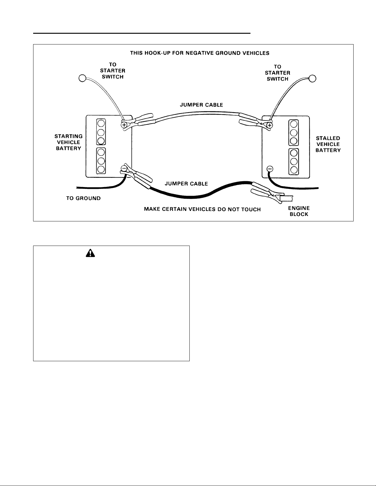
JUMP STARTING WITH AUXILIARY
(BOOSTER) BATTERY
Jump starting is not recommended. However, if it must
be done, follow these directions. Both booster and discharged batteries should be treated carefully when using
jumper cables. Follow the steps below EXACTLY, being
careful not to cause sparks. Refer to figure 24.
1. Both batteries must be of the same voltage (6, 12,
etc.).
2. Position the vehicle with the booster battery adjacent
to the vehicle with the discharged battery so that
booster cables can be connected easily to the batteries in both vehicles. Make certain vehicles do not
touch each other.
3. Wear safety glasses and shield eyes and face from
batteries at all times. Be sure vent caps are tight.
Place damp cloth over vent caps on both batteries.
4. Connect positive (+) cable to positive post of discharged battery (wired to starter or solenoid).
5. Connect the other end of same cable to same post
marked positive (+) on booster battery.
6. Connect the second cable negative (-) to other post
of booster battery.
7. Make final connection on engine block of stalled vehicle away from battery. Do not lean over batteries.
8. Start the engine of the vehicle with the booster battery. Wait a few minutes, then attempt to start the
engine of the vehicle with the discharged battery.
9. If the vehicle does not start after cranking for thirty
seconds, STOP PROCEDURE. More than thirty seconds seldom starts the engine unless some mechanical adjustment is made.
10.After starting, allow the engine to return to idle speed.
Remove the cable connection at the engine or frame.
Then remove the other end of the same cable from
the booster battery.
11.Remove the other cable by disconnecting at the discharged battery first and then disconnect the opposite end from the booster battery.
12.Discard the damp cloths that were placed over the
battery vent caps.
Troubleshooting & Repair
WARNING
For your personal safety, use extreme care when
jump starting. Never expose battery to open
flame or electric spark – battery action generates
hydrogen gas which is flammable and explosive.
Do not allow battery acid to contact skin, eyes,
fabrics, or painted surfaces. Batteries contain a
sulfuric acid solution which can cause serious
personal injury or property damage.
CAUTION
To avoid engine damage, do not disconnect battery while engine is running. Be sure terminal
connections are tight before starting.
WARNING
Keep open flames and sparks away from the battery; the gasses coming from it are highly explosive. Ventilate the battery well during charging.
Page 27
23
Troubleshooting & Repair
WARNING
Any procedure other than the preceding could
result in: (1) personal injury caused by electrolyte squirting out the battery vents, (2) personal injury or property damage due to battery
explosion, (3) damage to the charging system of
the booster vehicle or of the immobilized vehicle.
Do not attempt to jump start a vehicle having a
frozen battery because the battery may rupture
or explode. If a frozen battery is suspected,
examine all fill vents on the battery. If ice can be
seen or if the electrolyte fluid cannot be seen, do
not attempt to start with jumper cables as long
as the battery remains frozen.
Figure 24. Jump Starting Diagram
BULB REPLACMENT
Dash Indicator Bulbs
1. Raise the hood and remove the plenum.
2. To remove a bulb, turn the socket and pull bulb out.
Headlight Bulb
1. Disconnect the two wires from back of headlight.
Note position to reconnect to same terminals.
2. Turn socket to left to disconnect and pull out.
3. Replace the bulb.
4. Align the two tabs and insert socket. Turn to the right
to lock. Terminals will be at 12 o’clock and 6 o’clock
positions.
Page 28
24
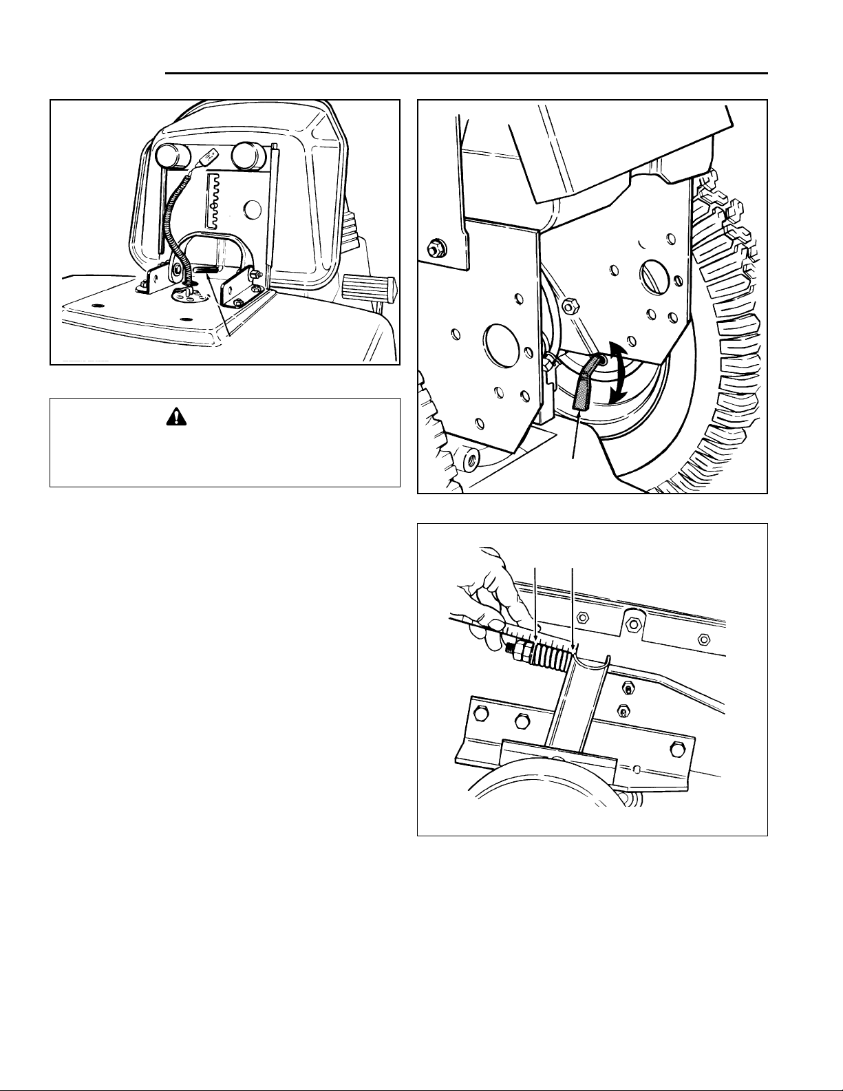
Parking Brake Adjustment
1. Set the parking brake.
2. Measure length of spring as shown in figure 27.
Measure along centerline of spring. Measurement
should be 1-5/8”.
3. Loosen the outer nut, then tighten or loosen inner nut
to attain dimension. When correct, tighten the outer
nut while holding the inner nut.
SEAT ADJUSTMENT
See figure 25. Use the lever to adjust the seat forward or
rearward for best rider comfort.
BRAKE ADJUSTMENTS
Brake Shoes
NOTE: On 18 HP models, engage the release valve (W, figure
2). On 20 HP models, place 2-speed axle shift (R, figure 2) in
neutral.
1. Place the tractor on a level surface. Place blocks in
front of the front wheels.
2. Place a jack under the drawbar and jack up tractor
until rear wheels are off the ground. Place a jackstand under each rear axle so tractor is secure.
3. The brake shoes are adjusted by turning an adjusting
star wheel inside the hub.See figure 26.
4. Remove the rubber plug from inside the braking
plate. Insert a brake tool inside the slot to engage the
teeth of the adjusting wheel.
5. Turn the adjusting wheel down to tighten the brake,
or up to loosen the brake. Turn only one notch at a
time, until you can just feel the brake shoes rubbing
as you rotate the tire by hand. When the brake shoes
just start rubbing, loosen the adjusting wheel one
notch.
6. Install the rubber plug and check the other rear
wheel.
Adjustments
*2374
WARNING
To avoid serious injury, perform adjustments
only with engine stopped, key removed and tractor on level ground.
Figure 25. Seat Adjustment
*1646
Figure 26. Brake Shoe Adjustment
Figure 27. Parking Brake Adjustment
Latch
Brake Tool
L.H. Side - 1-9/16”
R.H. Side - 1-5/8”
Page 29
FRONT CLUTCH ADJUSTMENT
Burnishing The Clutch
Before the front clutch is used for the first time, it should
be burnished as follows. Also, if mower cut is rough looking, the clutch may require burnishing. To burnish the
clutch, the mower must be installed.
1. Start the engine and set at full throttle.
2. Pull the front PTO switch out to the on position, leave
for 15 seconds, then push in to the off position.
3. Repeat ten times to burnish the clutch.
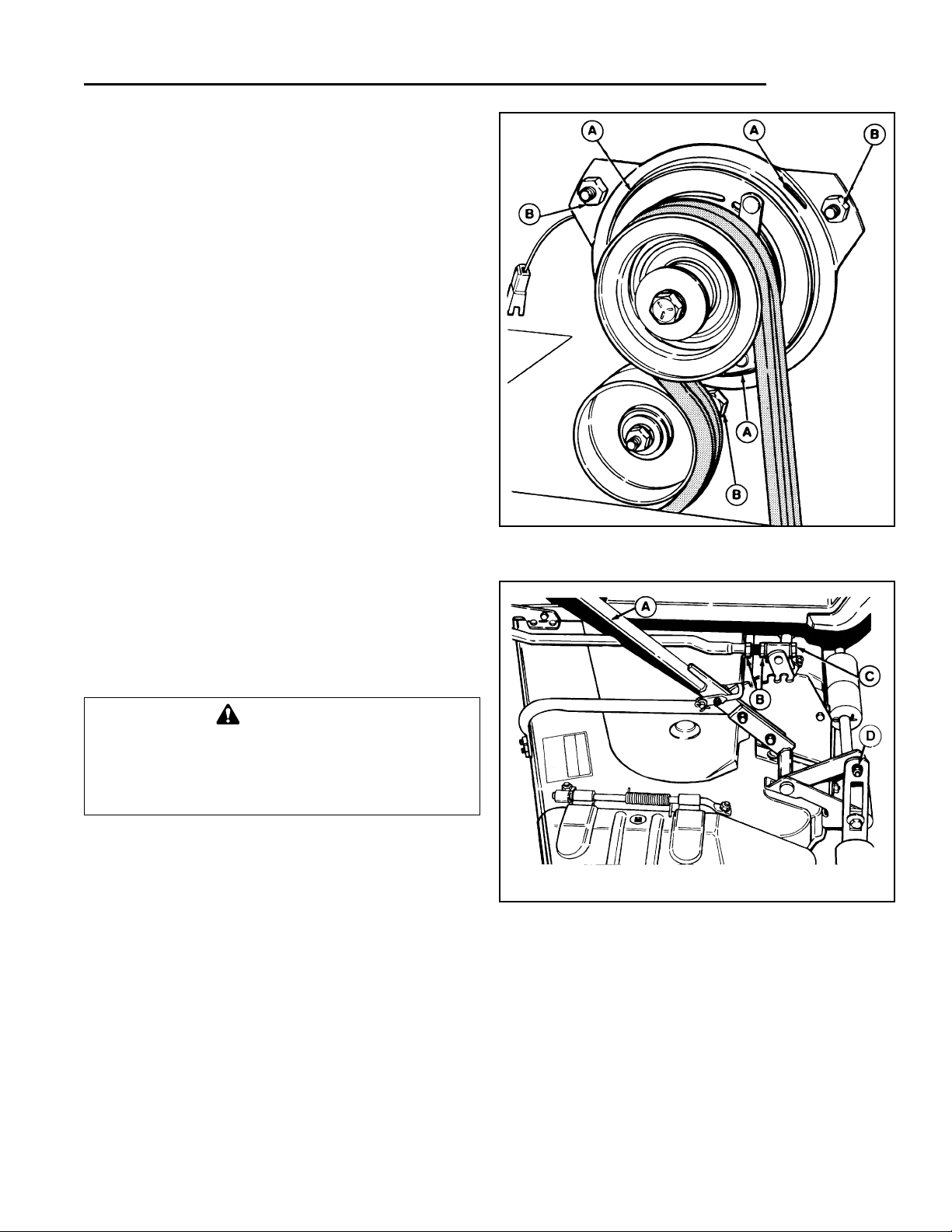
Clutch Adjustment
1. Remove the tractor hood by disconnecting the headlight coupler and then removing two pins and clip.
2. Use a 0.010” - 0.012” feeler gauge to check front
clutch at three slots (A, figure 28). There should be a
slight resistance as gauge is moved in and out of slot.
If tight or loose, proceed to step 3.
3. Loosen or tighten one of the nuts (B, figure 28) to
achieve slight drag on feeler gauge. Check the other
two slots and adjust accordingly.
NOTE: Adjustment at one location will change adjustment at the two other slots. Make sure all three locations
have proper adjustment.
LEVELING THE MOWER
If the cut is uneven, the mower may need leveling.
Unequal or improper tire pressure may also cause an
uneven cut. Make sure tire pressure is correct as specified in Checking Tire Pressure.
1. With the mower installed, place the tractor on a
smooth, level surface such as a concrete floor. Turn
the front wheels straight forward.
2. Check for bent blades and replace if necessary.
3. Disengage the PTO. Place the mower in mid-cut
position.
4. Arrange the mower blades so that they are pointing
from side-to-side. Measure the distance from the outside tips of the blades to the ground. If the difference
between the two measurements is less than 1/8” (3
mm), the mower is level side-to-side and you can
skip step 5.
25
Adjustments
*1645
Figure 28. Front PTO Adjustment
A. Slot B. Nut
*1680
Figure 29. Mower Leveling
A. Lever C. Bolt
B. Jam Nut D. Hardware
WARNING
Before checking mower, shut off PTO and
engine. Allow all moving parts to stop. Remove
ignition key, then disconnect the spark plug wire
and fasten it away from the spark plug.
5. Loosen the hardware (D, figure 29) securing roller
bar bracket to lift lever bracket. Raise or lower rollers
as necessary to level mower. Tighten hardware and
check measurement again.
6. Position blades front-to-back. Measure from front tip
of center blade to ground and from the rear tip of
either side blade to ground. The front measurement
at center blade should be 1/8” - 1/4” higher. To
Page 30
26
Adjustments
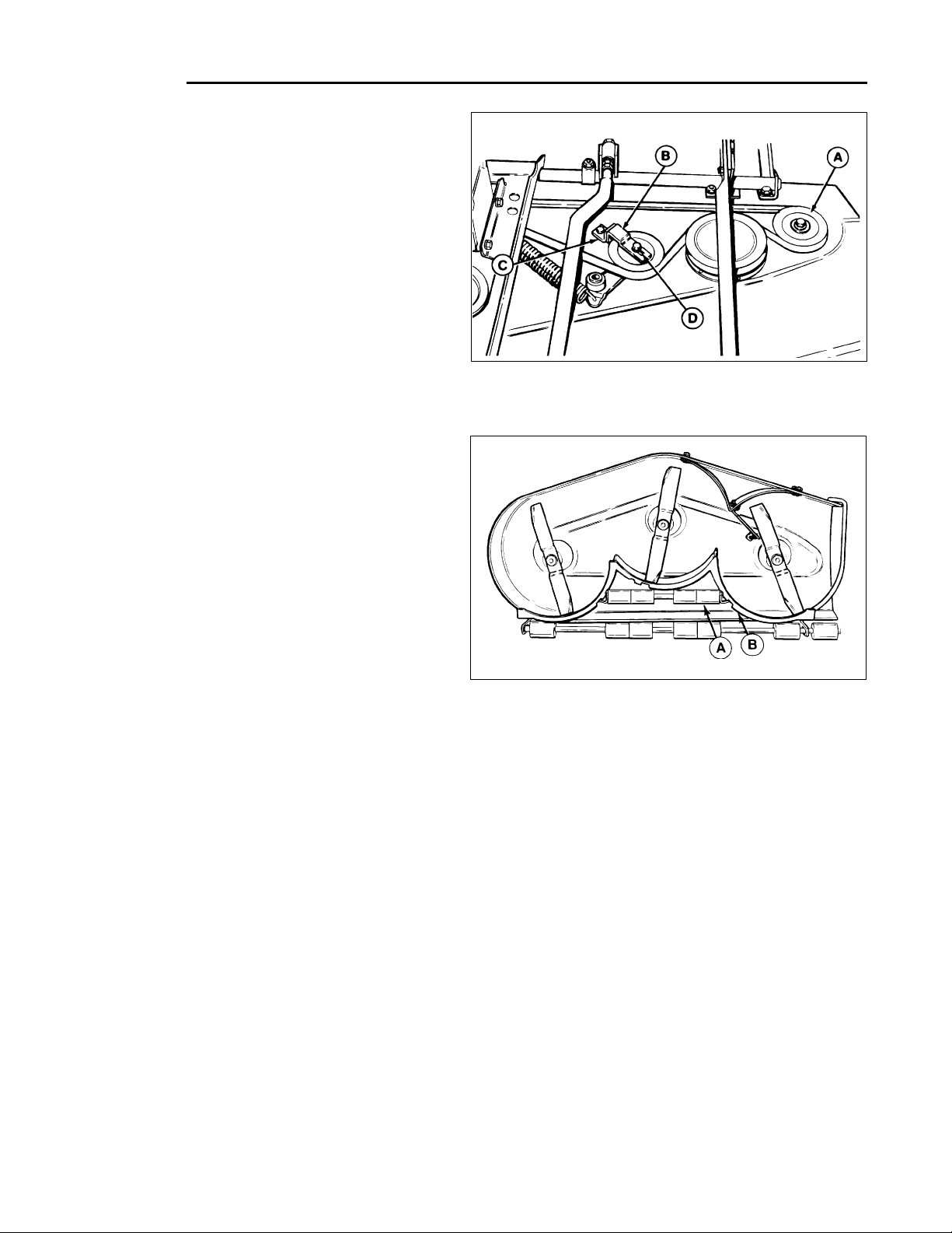
Figure 30. Idler Bracket
A. Idler Pulley C. Stop
B. Bracket D. Slot
adjust, proceed to step 7.
7. See figure 28. Loosen both jam nuts (B) on both rods
(only one shown). Turn the bolt (C) in to raise front of
mower, or out to lower front of mower. Be sure to
adjust both sides equally.
8. When measurement is correct, tighten both nuts (B)
securely while holding bolt (C).
ADJUSTMENTS FOR THE 60” MOWER
Idler Bracket
1. When the belt is installed, the bracket (B, figure 30)
should touch the stop (C, figure 30). The bracket has a
slot (D) so it can be adjusted. If necessary, loosen the
fasteners and move the bracket (B) toward the stop.
2. If the bracket cannot be moved far enough to touch the
stop (C), the idler pulley (A) can be repositioned.
Remove the mounting hardware, noting the position.
Reinstall the pulley in the hole in the mower deck which
is slightly farther away from center of mower.
Roller Bracket
The anti-scalping rollers (A, figure 31) can be adjusted for
different cutting heights by positioning roller brackets on the
mower baffle (B, figure 31).
1. Remove bolts, lockwashers and nuts securing roller
bracket to baffle.
2. For the lowest two cutting heights, roller brackets should
be positioned in the upper set of holes.
3. Use the lower set of holes if mowing is usually done at
higher cutting heights, or if scalping occurs at lower cutting heights due to uneven terrain.
BLADE BRAKE ADJUSTMENT
Mower blades and mower drive belt should come to a
complete stop within five seconds after front PTO switch
is turned off.
1. With tractor in neutral, PTO disengaged and operator
in seat, start the tractor engine.
*1684
Figure 31. Anti-Scalping Rollers
A. Rollers B. Mower Baffle
*1606
2. Look over the left-hand footrest at the mower drive
belt. Engage the front PTO and wait several seconds. Disengage the front PTO and check the
amount of time it takes for the mower drive belt to
stop.
3. If mower drive belt does not stop within five seconds,
perform the steps described under Front Clutch
Adjustment. Repeat steps 1 and 2. If belt still does
not stop within 5 seconds, see your dealer.
Page 31
CAUTION
To avoid damaging belts, do not pry belts over
pulleys.
27
Belt Replacement
TRACTOR PTO BELTS
1. Park the tractor on a smooth, level surface such as a
concrete floor. Disengage the PTO, turn off the
engine and lock the parking brake. Remove the key.
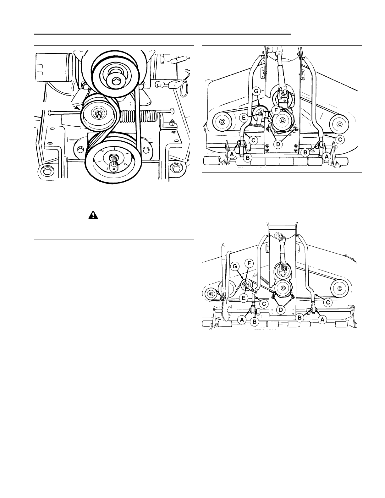
2. See figure 32. Move the idler pulley to relieve belt
tension.
3. Remove the belts from the pulleys.
MOWER BELT
48” mowers refer to figure 33.
60” mowers refer to figure 34.
1. Set the parking brake, disengage the PTO, turn off
engine and remove the key.
2. Remove mower from the tractor.
3. Remove the covers from the mower deck to expose
the belt.
4. Remove the cotter pins (A) and trunnion pins (B).
Move the two arm assemblies (C) up out of the way.
5. Remove cotter pins (not shown) and remove lift clevises (D).
6. Loosen the idler pulley nut (E) and move idler pulley
Figure 32. Tractor PTO Belts
*2529
Figure 33. Mower Belt - 48” Mower
A. Cotter Pin (2) E. Nut, Idler Pulley
B. Trunnion Pin (2) F. Stop, Idler Pulley
C. Arm Assy. (2) G. Idler Pulley
D. Lift Clevis (2)
*2530
Figure 34. Mower Belt - 60” Mower
A. Cotter Pin (2) E. Nut, Idler Pulley
B. Trunnion Pin (2) F. Stop, Idler Pulley
C. Arm Assy. (2) G. Idler Pulley
D. Lift Clevis (2)
*2531
stop (F) aside. Move idler pulley (G) to relieve belt
tension.
7. Remove the belt from the pulleys.
8. To install a new belt, reverse steps 1 - 6. Follow the
belt pattern as shown. Make sure idler pulley stop (F)
is positioned as shown.
Idler Pulley
Page 32

28
Specifications
ENGINE
18 HP Kohler
Model Command OHV
Horsepower 18 HP @ 3600 rpm
Cylinders 2
Bore 3.03 In. (77 mm)
Stroke 2.64 In. (67 mm)
Displacement 38 Cu. In. (624 cc)
Construction Cast Iron Sleeves,
Aluminum Crankcase
Electrical 12 Volt, 15 Amp Alternator Regulated Battery:
System 400 Cold Cranking Amps, 90 min. Reserve
Capacity, Industrial Rated Starter Motor
Ignition Electronic Ignition
Governor Internal Flyweight with external Adjustment
Air Cleaner Dual Element
Lubrication Full Pressure Lube with Oil Filter
Oil Capacity 2 Quarts (1.9 L)
Fuel Tank Material: Non-Corrosive Polyethylene
Fuel Tank, Capacity: 4.2 Gallons
Muffler Quiet Compact, Low Back Pressure
20 HP Briggs & Stratton
Model Vanguard
Horsepower 20 HP @ 3600 rpm
Cylinders 2
Bore 2.83 In. (72 mm)
Stroke 2.75 In. (70 mm)
Displacement 34.75 Cu. In. (570 cc)
Construction Cast Iron Sleeves,
Aluminum Crankcase
Electrical 12 Volt, 16 Amp Alternator Regulated Battery:
System 400 Cold Cranking Amps, 90 min. Reserve
Capacity, Industrial Rated Starter Motor
Ignition Electronic Ignition
Governor Internal Flyweight with external Adjustment
Air Cleaner Dual Element
Lubrication Full Pressure Lube with Oil Filter
Oil Capacity 3.5 Pints (1.66 L)
Fuel Tank Material: Non-Corrosive Polyethylene
Fuel Tank, Capacity: 4.2 Gallons
Muffler Quiet Compact, Low Back Pressure
TRANSMISSION
Type Hydrostatic
Pump Variable Displacement Axial Type
Motor Fixed Displacement Reversible Axial Type
Hydraulic Fluid Type F Transmission Fluid
Reservoir: 6 Qt. Capacity (5.7 L)
Filter: Cartridge w/25 Micron Rating
Full Flow w/o Anti-Drain Back
Control Shock Absorber Dampened Single Lever
w/Brake Return
18 HP Model - Free Wheeling Valve for Manual
Tractor Movement
20 HP Model - Two Range Transmission
w/Traction Control Hi/Lo Range Control
Lever Right Side of Seat; Neutral Detent
w/Safety Start Switch
Speeds Continuously Variable , Forward & Reverse
@3400 RPM
Differential Planetary Bevel Gear
Engine Speed 18 HP Model: Forward 0-8 MPH
Reverse 0-4.5 MPH
20 HP Model: Forward 0-8 MPH-Hi, 0.5.5 MPH-Lo
Reverse 0.4.5 MPH-Hi
Reverse 0.3.25 MPH-Lo
Final Drive Hardened Spur Gears
Rolling Contact Bearings
CONTROLS
Steering Full Circle Steering Wheel
Hydrostatic Power Steering
Brake Pedal Location Right Front; Internally Expanding Self-
Energizing Automotive Style Drum Brake; Parking
Brake Lock Standard Equipment; Brake Pedals
Cause Return To Neutral When Depressed
Together
Location Implement Lift Lever: Left side (Hydraulic)
PTO Clutch: Dash Mounted Switch
Ground Speed Control Lever: Right Side
Ignition Key: On Dash
Light Switch: On Dash
Throttle Control: On Dash, Left Side
Choke Control: On Dash
Voltmeter: On Dash (20 HP model only)
Hourmeter: On Dash
Fuel Gauge: On Dash (20 HP model)
On Gas Cap (18 HP model)
Parking Brake Lock: On Dash, Lower Right Side
NOTE: Specifications are correct at time of printing and are subject to change without notice.
Page 33
CHASSIS
Frame Side Rail Construction; Electrically Welded Heavy
Guage Steel
Power Take-Off Points: Front & Rear (Opt.)
Engine Mounting Above Front Axle
Pivot Point Location: double Pivoting Heavy Duty
Cast Front Axle
Rear Wheels Tire Size 23 x 10.5-12 or 24 x 13 x 12
Pneumatic Inflation Pressure 6-8 psi (41-55 kPa)
Front Wheels Tire Size 16 x 6.50-8
Pneumatic Inflation Pressure 12-15 psi
(82-103 kPa)
Accessibility Hood Tips Forward
Seat Type Bucket, High Back, Adjustable w/
Spring Suspension
Turning Radius Inside Rear Tire 26 In. w/o brake applied
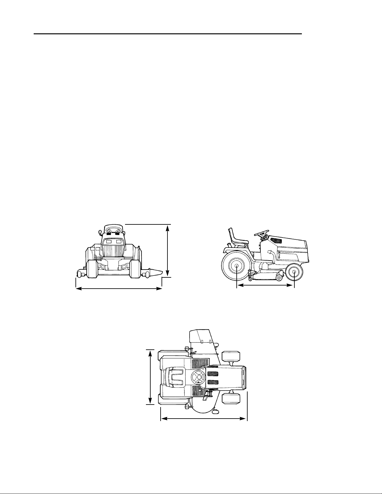
DIMENSIONS
Overall Length 78 In.
Overall Width 38-1/4 In.
Height To Top of Steering Wheel 47 In.
Wheel Base 51 In.
Weight (approx.)
w/o mower 18 HP Model: 825 lbs.
20 HP Model: 873 lbs.
29
Specifications
60” Mower - 74”
48” Mower - 62”
47”
38-1/4”
78”
51”
Page 34

30
Parts & Accessories
COMMON REPLACEMENT PARTS
Listed below are the more common replacement parts. Only
genuine factory replacement parts will assure optimum performance and safety. Do not attempt repairs or maintenance unless
proper procedures and safety precautions are followed. For
assistance in any area, see your dealer.
QTY. DESCRIPTION PART NO.
Mower Blades
3 - 42" Deck 1679917
3 - 48" Deck 1679916
2 - 60" Deck, R.H. & Center 1702365
1 - 60" Deck, L.H. 1702366
Mower Belts
1 - 42" Deck 1675282
1 - 48" Deck 1675342
1 - 60" Deck 1700345
1 Tractor PTO Belt (Matched set of 2) 1708529
1 Oil Filter - Hydro Pump 1650954
1 Ignition Key Set ( 2 keys on a ring) 1714054
1 Battery 1685289
2 Mower Hitch Pins 156306
2 Clips for Mower Pins 176012
1 Headlamp Bulb 1677371
MAINTENANCE ITEMS
• Simplicity Engine Oils
Case of 12 qts. (Your dealer has 1 qt. cans)
-SAE 5W-30 SF/CD (Cold Weather 30°& under) 1685576
-SAE 30W 3G/CC (Warm weather 32° & up) 1685659
• Touch-Up Paint
Deep Orange Spray Paint, 13 oz. Can 1685611
Deep Orange Paint, 1 qt. 1685612
Black Spray Paint, 13 oz. Can 1685639
Red Spray Paint, 13 oz. Can 1685722
Metallic Gray, 13 oz. Can (Wheels) 1685718
• Touch-Up Daubers
Deep Orange 1/2 oz. w/Brush Cap 1685615
• Grease Gun Kit w/8 oz. Grease Tube 1685510
Replacement 8 oz. Grease Tube for above 103077
• Tire Sealant-Stops Tire Leaks. Prevents Flats.
11 oz. Tube 1685523
• Gas Can-No Tip Design. Durable Polyethylene.
1 gallon 1685587
2-1/2 gallon 1685555
5-1/4 gallon 1685556
• Cleaner, Polish, Sealant & Protectant
8 oz. Bottle 1685696
• Degrimer/Degreaser
32 oz. Bottle w/Trigger Spray 1685619
1 gallon 1685621
USE ONLY GENUINE
FACTORY REPLACEMENT PARTS
Available Through Your Local
Authorized Dealer
Page 35
31
Parts & Accessories
OPTIONAL ACCESSORIES
See your dealer to purchase these items.
Loader & Bucket
Turbo Wide Body Cart Collector
Dump Cart
40” & 47" Snowthrower
42" Dozer Blade
38” Tiller
Tire Chains
Snow Cab
Additional Technical Literature Available
Operators Manuals
Additional copies of this manual are availble, (and as part of commitment to provind a product
that will last you for many years, we maintain a stock of printed operators manuals going back
over 25 years!)
Parts Manuals
Fully illustrated parts manuals are also available — these
manuals show all of the assemblies and components of
your product in exploded views which show the relationship of the parts and how they go together, as well as
giving the component part numbers and quantities
used. Important assembly notes and special torque values are included in these manuals.
Repair & Service Manuals
In addition, for many models, we have in-depth repair & Service Manuals
available, which take you step-by-step through maintenance, tear-down, component replacement and re-assembly procedures.
For the available manuals applicable for your
model, contact the Customer Publications
Department at 414-284-8519. Have the information listed in the box at the right available
when phoning in your request.
Technical Manuals
Model:
Mfg. No.:
Your Name:
Address:
City, State, Zip:
Visa/Mastercard No.:
Card Expiration Date:
Page 36

32
Fast
Slow
Operator Present
Switch (Seat)
PTO Engaged
Parking Brake
Choke
Engine Running
Lights
Oil Pressure
Forward
Reverse
International Symbols
 Loading...