

Simplicity Landlord DLX Series, 1717H, 2700 Series, 1700 Series, 1718H Dealer Setup & Adjustment Instructions Manual
...Page 1

How to use this file...(Dealer Setup & Adjustment Guides)
————————————————————————————————————————————–––
Instructions for
Print Vendors (Paper Manuals)
Paper Size: * 8-1/2 x 11
* Body—50 lbs brilliant white offset or equivalent.
Press: * Body—1-color, 2-sided
Bindery: * 3-Hole Drill (Dealer Setup Guides must ALWAYS be 3-Hole Drilled!)
• UL Corner Stitch (Unless being prined as part of a “complete” set of Guides with Tabs).
COVERS: * This document is a self-covered piece.
• Check the front cover for the individual document number (a TP 300-XXXX-XX-XX-SMA number).
BODY: * REMEMBER: ODD number pages are ALWAYS right hand pages, and EVEN number are ALWAYS
left hand pages.
General: * This instruction page is NOT part of the manual and must NOT be printed.
• Pages labeled with the text “THIS PAGE INTENTIONALLY BLANK” are placement pages ONLY,
and should NOT be printed.
————————————————————————————————————————————–––
If you have further questions on how to utilize this file, please contact
Simplicity Technical Publications Department at (262) 284-8647.
Page 2

THIS PAGE INTENTIONALLY BLANK
Page 3

1/2001 1
TP 300-2226-02-LL-SMA
Dealer Setup
& Adjustment Instructions
Landlord DLX / 1700 / 2700 Series Tractors and Mowers
TABLE OF CONTENTS:
SAFETY RULES .................................................................2
SETUP PROCEDURES
Quick Setup List ................................................................3
Uncrating............................................................................4
Battery Activation & Installation ......................................4
Tractor Assembly ..............................................................6
Steering Wheel Assembly................................................6
Seat and Safety Switch Assembly ...................................6
Check Fluid levels .............................................................7
Fill and Check Engine Oil.................................................7
Check Transmission Oil ...................................................7
Engine Coolant ................................................................8
Inspect Cooling System ...................................................8
Reduce and Check Tire Pressure ....................................8
Lubrication .........................................................................9
Lubricate Rear Axle Shafts ............................................10
Mower Assembly .............................................................11
Torque Mower Blade Bolts.............................................11
Hitch and Leveling Rod Assembly .................................11
Mower Deck Installation ................................................12
Leveling Mower Deck ......................................................15
Side-to-Side Leveling.....................................................15
Front-to-Back Leveling...................................................15
Perform Safety Checks ...................................................16
Functional Tests.............................................................16
Dash Safety Lights Test.................................................16
Mower Blade Stopping Check........................................16
Seat Switch Connection.................................................16
Safety Interlock System .................................................17
Burnishing the Electric PTO Clutch...............................17
ADJUSTMENT PROCEDURES
Electric PTO Clutch Adjustment ....................................18
Steering Gear Adjustment ..............................................18
Brake Spring Adjustment ...............................................19
Foot Pedal Height Adjustment (Forward Speed)..........19
Cruise Control Adjustment.............................................20
Internal Neutral Adjustment ...........................................20
Differential Lock Cable Adjustment...............................21
Transmission Maintenance ............................................21
Belt Replacement ............................................................24
ATTENTION SETUP PERSONNEL:
Sections and items denoted by the Setup
symbol provide the information necessary
to fully assemble, test, and prepare the
units described above for delivery to your customers.
A Quick Setup List
is provided on page 3 of this
booklet to help you identify and check that the
items have been performed.
Additional information concerning functional
tests, general adjustment procedures, and
the location of normal lubrication points are
included in these instructions.
Although all required lubrication and normal adjustments on factory-assembled components are done at
the factory, this additional information is provided to
assist you in ensuring that each unit is delivered to
the customer in proper working order.
The safety warnings provided in this guide
and in the operator's manual included with
the unit contain important information that
must be obeyed when assembling, setting-up, operating, servicing, transporting, or storing the unit.
These warnings are highlighted by the safety alert triangle symbol shown above, which signifies that an
important safety message is being provided.
You must read, understand, and follow these
warnings and instructions, and use safe shop and
work practices at all times while working on or
around this unit and all other outdoor power
equipment.
Mfg. No. Description
Tractors
1693379 Landlord DLX, 17HP LC
1693381 Landlord DLX, 18HP
1693383 Landlord DLX, 20HP
1693387 Landlord DLX, 17HP LC (Export)
1693389 Landlord DLX, 18HP (Export)
1693391 Landlord DLX, 20HP (Export)
1693395 1717H, 17HP LC
1693397 1718H, 18HP
1693399 1720H, 20HP
1693401 2717H, 17HP LC
1693403 2718H, 18HP Hydro
1693405 2720H, 20HP Hydro
Mfg. No. Description
Tractors
1693804 Landlord DLX, 23HP Hydro
1693805 Landlord DLX, 23HP Hydro (Export)
1693806 Landlord DLX, 18HP Hydro
1693807 Landlord DLX, 18HP Hydro (Export)
1693814 1723H, 23HP Hydro
1693815 2723H, 23HP Hydro
1693835 1718H, 18HP Hydro
1693857 2718H, 18HP Hydro
1693895 Landlord DLX, 18HP
1693896 1718h, 18HP Hydro
1693897 2718H, 18HP
1693898 Landlord DLX, 18HP (Export)
Mfg. No. Description
Mower Decks
1692686 44” Mower Deck
1692687 44” Mower Deck
1692688 50” Mower Deck
1692689 50” Mower Deck
1692881 50” Mower Deck (LC & Export)
1692882 50” Mower Deck
1693172 44” Mower Deck (Export)
1693629 54” Mower Deck
1693631 54” Mower Deck
1693727 54” Mower Deck (Export)
This Dealer Setup Instruction covers the following products:
Page 4

Landlord / 1700 / 2700 Series
TP 300-2226-02-LL-SMA
1/20012
Read these safety rules and follow them closely. Failure to obey these rules could result in loss of control of equipment, severe personal injury or death to you, yourself or bystanders, or damage to property or equipment. This mowing deck is capable of amputating hands and feet and throwing objects. The triangle in text signifies important cautions or warnings which must be followed.
IMPORTANT – Safe operation practices for riding mowers.
I. General operation
1. Read, understand, and follow all instructions in the manual and on
the unit before starting.
2. Only allow responsible adults, who are familiar with the instructions, to operate the unit.
3. Clear the area of objects such as rocks, toys, wire, etc., which
could be picked up and thrown by the blade(s).
4. Be sure the area is clear of other people before mowing. Stop the
unit if anyone enters the area.
5. Never carry passengers.
6. Do not mow in reverse unless absolutely necessary. Always look
down and behind before and while backing.
7. Be aware of the mower discharge direction and do not point it at
anyone. Do not operate the mower without either the entire grass
catcher or the guard in place.
8. Slow down before turning.
9. Never leave a running unit unattended. Always turn off blades, set
parking brake, stop engine, and remove keys before dismounting.
10. Turn off blades when not mowing.
11. Stop engine before removing grass catcher or unclogging chute.
12. Mow only in daylight or good artificial light.
13. Do not operate the unit while under the influence of alcohol or
drugs.
14. Watch for traffic when operating near or crossing roadways.
15. Use extra care when loading or unloading the unit into a trailer or
truck.
II. Slope operation
Slopes are a major factor related to loss-of-control and tip-over accidents, which can result in severe injury or death. All slopes require
extra caution. If you cannot back up the slope or if you feel uneasy on
it, do not mow it.
DO
• See your authorized dealer for recommendations of wheel weights
or counterweights to improve stability.
• Mow up and down slopes, not across.
• Remove obstacles such as rocks, tree limbs, etc.
• Watch for holes, ruts, or bumps. Uneven terrain could overturn the
unit. Tall grass can hide obstacles.
• Use slow ground speed so that you will not have to stop or change
speeds while on the slope.
• Use extra care with grass catchers or other attachments. These
can change the stability of the unit.
• Keep all movement on the slopes slow and gradual. Do not make
sudden changes in speed or direction.
• Avoid starting or stopping on a slope. If tires lose traction, disengage the blade(s) and proceed slowly straight down the slope.
DO NOT
• Do not turn on slopes unless necessary, and then, turn slowly and
gradually downhill, if possible.
• Do not mow near drop-offs, ditches, or embankments. The unit
could suddenly turn over if a wheel is over the edge of a cliff or
ditch, or if an edge caves in.
• Do not mow on wet grass. Reduced traction could cause sliding.
• Do not try to stabilize the unit by putting your foot on the ground.
• Do not use grass catcher on steep slopes.
III. Children
Tragic accidents can occur if the operator is not alert to the presence
of children. Children are often attracted to the unit and the mowing
activity. Never assume that children will remain where you last saw
them.
1. Keep children out of the mowing area and under the watchful care
of another responsible adult.
2. Be alert and turn unit off if children enter the area.
3. Before and when backing, look behind and down for small children.
4. Never carry children. They may fall off and be seriously injured or
interfere with safe unit operation.
5. Never allow children to operate the unit.
6. Use extra care when approaching blind corners, shrubs, trees, or
other objects that may obscure vision.
IV. Service
1. Use extra care in handling gasoline and other fuels. They are flammable and vapors are explosive.
a) Use only an approved container.
b) Never remove gas cap or add fuel with the engine running.
Allow engine to cool before refueling. Do not smoke.
c) Never refuel the unit indoors.
d) Never store the unit or fuel container inside where there is an
open flame, such as a water heater.
d) Clean up oil and fuel spills immediately.
2. Never run a unit inside a closed area.
3. Keep nuts and bolts, especially blade attachment bolts, tight and
keep equipment in good condition.
4. Never tamper with safety devices. Check their proper operation
regularly.
5. Keep equipment free of grass, leaves, or other debris build-up.
6. Stop and inspect the equipment if you strike an object. Repair, if
necessary, before restarting.
7. Never make adjustments or repairs with the engine running.
8. Grass catcher components are subject to wear, damage, and deterioration, which could expose moving parts or allow objects to be
thrown. Frequently check components and replace, when necessary, with manufacturer’s recommended parts.
9. Mower blades are sharp and can cut. Wrap the blade(s) or wear
gloves, and use extra caution when servicing them.
10. Check brake operation frequently. Adjust and service as required.
11. Allow the unit to cool before storing.
WARNING – SLOPE OPERATION
Never operate on slopes greater than 17.6 percent (10°) which is a
rise of 3-1/2 feet (106 cm) vertically in 20 feet (607 cm) horizontally.
When operating on slopes that are greater than 15 percent (8.5°)
but less than 30 percent use front counterweights and rear wheel
weights (see your dealer). Select slow ground speed before driving
onto slope. In addition to front and rear weights, use extra caution
when operating on slopes with rear-mounted grass catcher. Mow
UP and DOWN the slope, never across the face, use caution when
changing directions and DO NOT START OR STOP ON SLOPE.
SAFETY RULES
Page 5

Landlord / 1700 / 2700 Series
1/2001 3
TP 300-2226-02-LL-SMA
Quick Setup List -
Page Setup Procedure Steps to Perform
4 Uncrating ❏ Remove Crate & Banding.
❏ Place Transmission Release Lever in PUSH position & Roll
Tractor forward off skid. (Note: You may want to assemble
the steering wheel at this time.)
4 Battery Activation ❏ Unpack Dry Batteries.
& Installation ❏ Fill Batteries with Electrolyte.
❏ Charge the Batteries (Note: proceed with other setup steps
while batteries are charging).
❏ Test Batteries with hydrometer or load-tester.
❏ Install & secure Batteries.
6 Tractor Assembly ❏ Assemble the Steering Wheel (Note that the thick spoke
faces the seat.)
❏ Assemble the Seat.
❏ Check the Seat Switch connection.
7-8 Check Fluid Levels ❏ Fill & check Engine oil level.
❏ Check Transaxle fluid level (if needed, add 10-W30
SG/CD Engine Oil).
❏ Check Coolant level (if needed, add mixture of 50% ethyl-
ene glycol, 50% distilled water).
❏ Inspect Cooling System.
❏ Reduce & check Tire Pressures
(Front tires 12-15 psi, Rear tires 6-8 psi).
9-10 Lubrication ❏ Lubricate all grease & oil points.
11-15 Mower Assembly ❏ Torque mower blades.
❏ Attach mower Hitch & Leveling Rod.
❏ Install Mower Deck onto Tractor and Attach Belt.
❏ Level Mower Deck (Side-to-side & Front-to-back).
16-17 SAFETY CHECKS ❏ Check for LOOSE HARDWARE.
❏ Check all OPERA
TOR CONTROLS.
❏ Check D
ASH SAFETY LIGHTS.
❏ Test P
ARKING BRAKE.
❏ Perform MO
WER BLADE STOPPING CHECK.
(Blade must stop within 5 seconds!)
❏ Perform SAFETY INTERLOCK SYSTEM CHECK
.
17 Burnish Electric Clutch ❏ Burnish Electric Clutch (run for 15 seconds, repeat 10
times).
❏ Repeat MO
WER BLADE STOPPING CHECK.
(Blade must stop within 5 seconds!)
Page 6
Landlord / 1700 / 2700 Series
TP 300-2226-02-LL-SMA
1/20014
Uncrating
1. Using a reciprocating utility saw or equivalent, cut
crate away from bottom skid. Remove crate. Remove
shrink-wrap plastic.
2. Cut banding from front and rear tractor axles. Cut
banding from mower rollers. Remove mower from bottom skid.
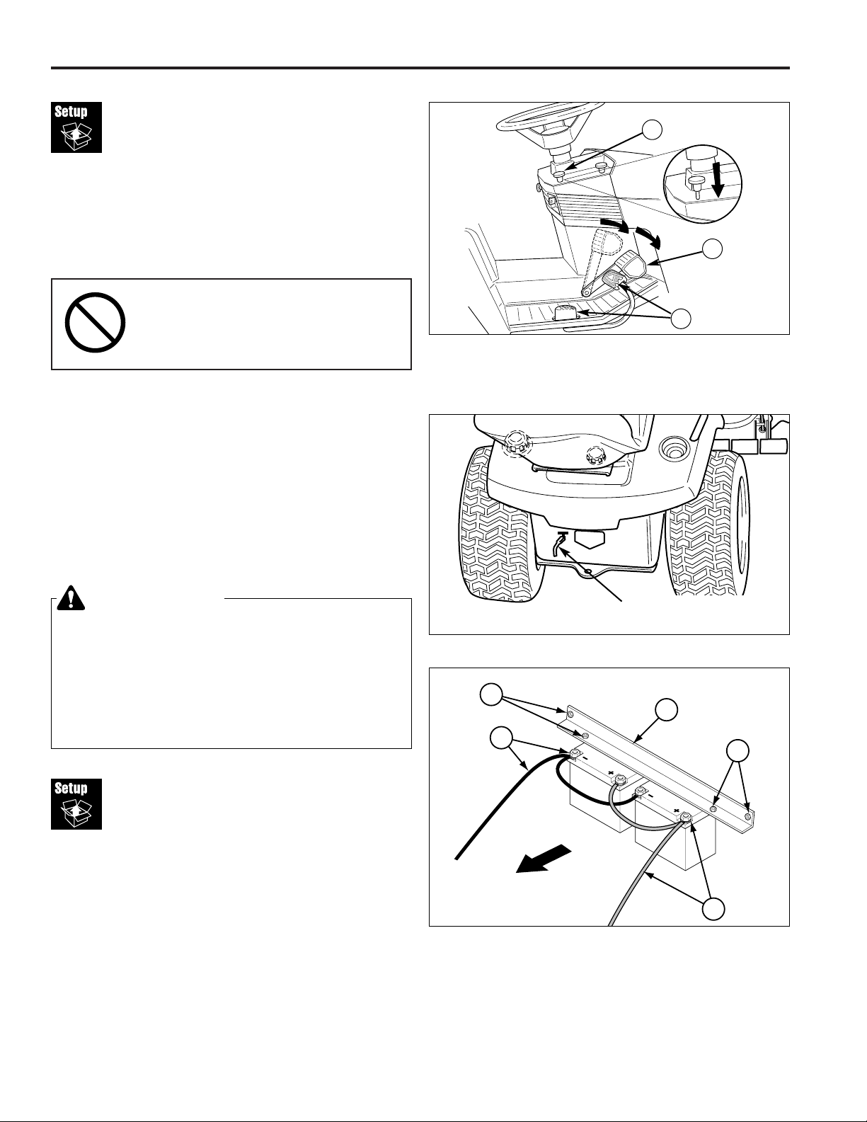
3. Hold down brake pedal (B, Figure 1) and push down
on parking brake knob (C) to release parking brake.
4. See Figure 2. Place hydro release lever in the PUSH
position by pulling the release lever handle up, back,
and down until it locks in the released position.
NOTE: You may want to install the steering wheel at this
time.
5. Be sure there are no nails or sharp objects on bottom
skid to puncture tractor tires. Roll the tractor forward
off the skid.
IMPORTANT NOTE
When cutting crate from bottom skid,
use caution around tractor tires and
mower rollers.
Battery Activation
& Installation
Removing the Batteries -
Liquid Cooled Models
1. Open the tractor hood by unlatching the rubber strap
hold-downs. Raise the hood.
2. The batteries are shipped in the rear section of the
engine compartment. Remove the four taptite screws
(D, Figure 3) securing the battery hold down bar (C).
Remove the hold down bar and cushion (not shown) .
3. Remove the dry batteries from the compartment.
Figure 3. Battery Connections
A. Negative (-) Cable & Terminal
B. Positive (+) Cable & Terminal
C. Hold Down Bar
D. Taptite Screws
E. Cushion (not shown)
Figure 1. Engaging the Parking Brake
A. Ground Speed Pedals
B. Brake Pedal
C. Parking Brake / Cruise Control Knob
A
B
C
Figure 2. Hydro Release Lever
Pull Lever Up, Back,
and Down to Release
WARNING
BATTERY SAFETY RULES
●●
Battery acid causes severe burns. Avoid
contact with skin.
●●
Remove battery from tractor for activation.
●●
Wear eye protection while activating battery.
●●
To avoid an explosion, keep flames and sparks
away from battery, especially while charging.
D
C
A
D
FRONT
B
Page 7
Removing the Battery -
Air Cooled Models
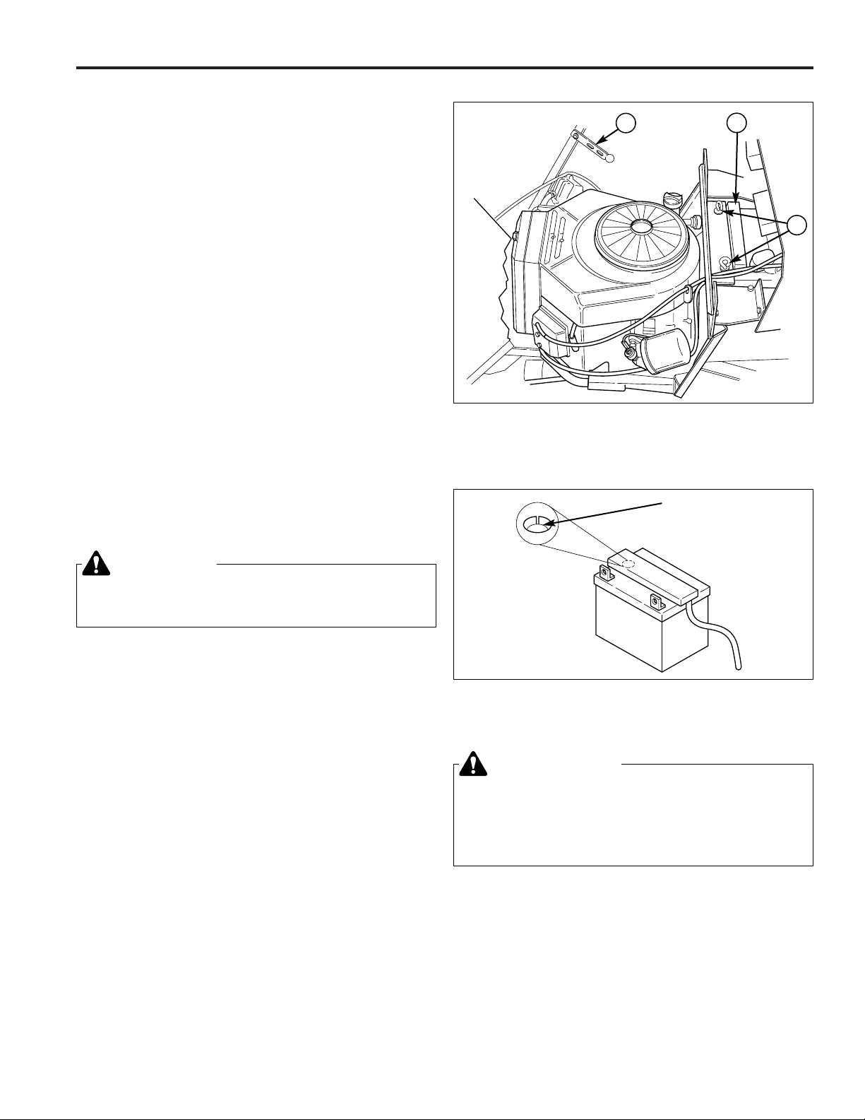
1. Open the tractor hood by unlatching the rubber strap
hold-downs (A, Figure 4). Raise the hood.
2. The battery is shipped in the rear section of the
engine compartment. Remove the hold-down rods
(C) and hold-down bar.
3. Remove the dry battery from the compartment.
Activating the Batteries
NOTE: Not required with maintenance free batteries. Go
to step D.
4. Prepare the dry batteries as follows:
a. Remove the vent cap(s) from the battery.
b. Fill the battery with electrolyte up to the bottom of
the split ring (Figure 5) and let stand for 20 minutes.
Do not overfill.
c. After 20 minutes, recheck the level and add electrolyte if necessary.
d. Charge the battery for 15 minutes with a trickle
charger (maximum charge rate: 10 amps).
NOTE: While charging the battery proceed with tractor
setup. Batteries can be installed as one of the last steps.
e. Reinstall the vent cap(s).
f. After charging, check the battery with a hydrometer or load-tester to make sure they are fully charged.
Battery Installation
LIQUID COOLED MODELS
5. Carefully place the batteries back in the engine compartment.
6. Attach the red positive cables (B, Figure 3) to the positive posts of both batteries EXACTLY AS SHOWN.
7. Attach the black negative cable (A, Figure 3) to the
negative posts of both batteries EXACTLY AS
SHOWN.
8. Lay the cushion across the top of the batteries.
9. Reinstall the battery hold down bar (C, Figure 3) and
secure with the four taptite screws (D).
Landlord / 1700 / 2700 Series
1/2001 5
TP 300-2226-02-LL-SMA
Figure 4. Engine Compartment 18 HP & 20 HP Briggs & Stratton Twin Cylinder
A. Hood Strap C. Hold-Down Rods
B. Vent Cap
A
B
C
Figure 5. Fill Battery with Electrolyte
Fill to Bottom of
Split Ring
10. Install the vent hoses on the batteries and route the
hoses out of the bottom right side of the engine compartment through the frame. Make sure the tubes go
all the way through the frame and will not drip on any
belts, pulleys, or the mower deck (note: maintenance
free batteries do not have vent hoses).
NOTICE
Batteries must be fully charged before operation
or the starter solenoid may malfunction.
WARNING
When installing battery cables, CONNECT THE
POSITIVE (+) CABLE FIRST and negative (-) cable
last. If not done in this order, the positive
terminal can be shorted to the frame by a tool.
Page 8
Landlord / 1700 / 2700 Series
TP 300-2226-02-LL-SMA
1/20016
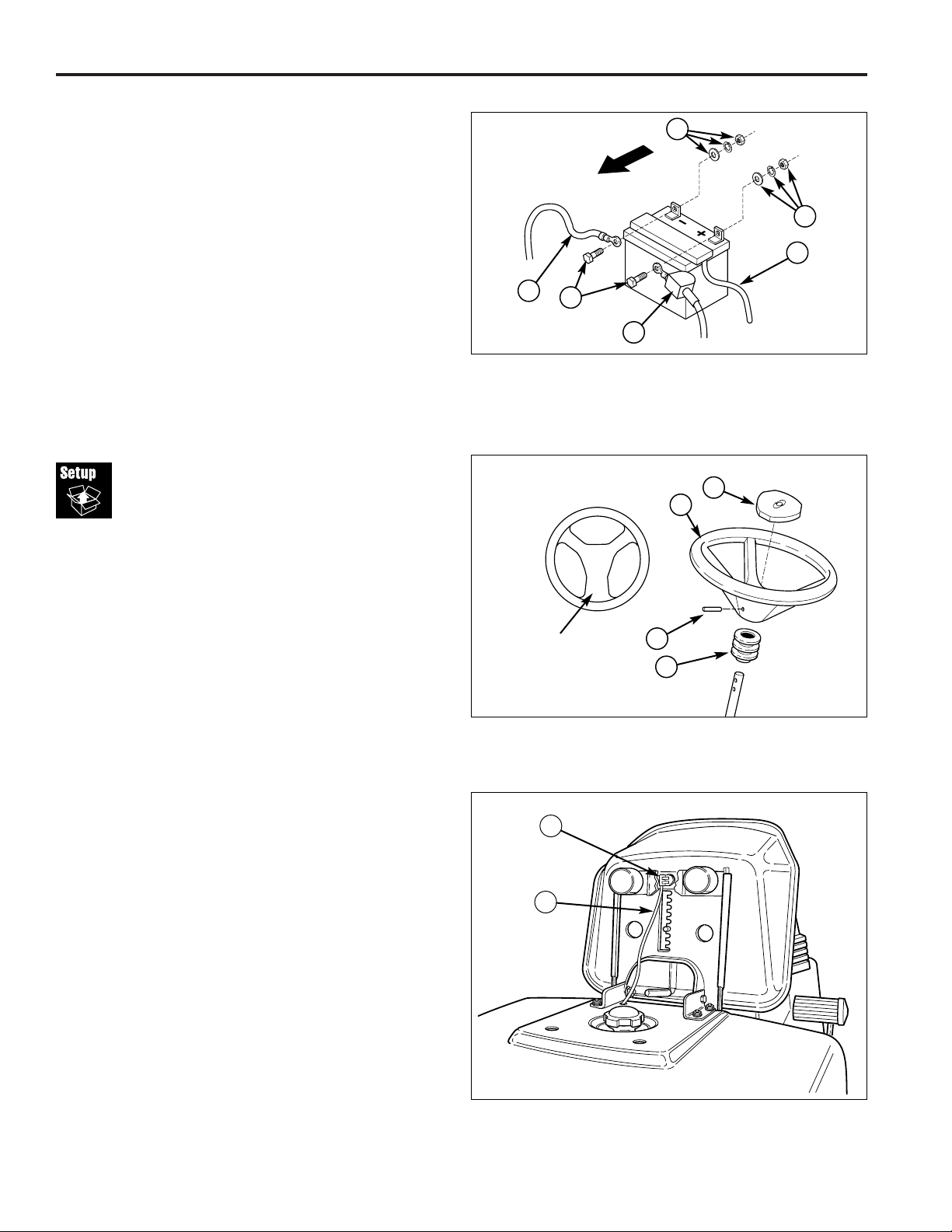
Figure 7. Steering Wheel Components
A. Steering Wheel C. Roll Pin , 5/16” x 2 1/2”
B. Cap D. Tube
Tractor
Assembly
Steering Wheel Assembly
1. Remove the plastic tie securing the steering wheel to
the steering shaft and transmission control lever.
2. Coat the steering shaft with anti-seize lubricant.
3. Make sure the steering tube (D, Figure 7) is placed
over the shaft, then place the steering wheel on the
shaft with thicker grip area facing the seat.
4. Align the hole in the steering wheel with the top hole
in the shaft, and insert roll pin (C) to secure steering
wheel to shaft. (Lower hole may be used if desired.)
5. Make sure the roll pin is driven in flush.
6. Make sure the cap (B) is fully engaged with the
matching recess in the steering wheel. (The cap is
removable, but is used only for decorative purposes
and does not provide access to any assembly hardware.)
NOTE: To prevent damage, do not use excessive force
to remove or attach plastic cap. Use soft-faced mallet if
cap must be tapped back into position.
Seat & Safety Switch Assembly
1. Assemble the seat to the seat slide bracket using the
whizlock bolts provided.
2. Make sure the seat safety switch is connected (A,
Figure 8).
3. Lower seat to normal riding position.
Figure 8. Seat Switch
A. Seat Switch B. Wiring Harness
Installing the Battery -
Air Cooled Models
5. Carefully place the battery back in the engine compartment (see Figure 4). Secure the battery using the
hold-down rods (C) and hold-down bar.
6. Attach the red positive cable (B, Figure 6) and cover
to the positive post as shown.
7. Attach the black negative cable (A, Figure 6) to the
negative post as shown.
8. Install the vent hose on the battery cap and route the
hoses out of the bottom right side of the engine compartment through the frame. Make sure the tubes go
all the way through the frame and will not drip on any
belts, pulleys, or the mower deck (note: maintenance
free batteries do not have vent hoses).
FRONT
Figure 6. 18HP & 20HP Battery Cables & Fill
A. Negative Cable D. Capscrew
B. Positive Cable & Cover E. Vent Hose
C. Nut, Lockwasher, & Washer
C
B
E
A
D
C
A
C
D
B
Thicker Spoke
Faces Seat
A
B
Page 9
Landlord / 1700 / 2700 Series
1/2001 7
TP 300-2226-02-LL-SMA
Check
Fluid Levels
Fill & Check Engine Oil
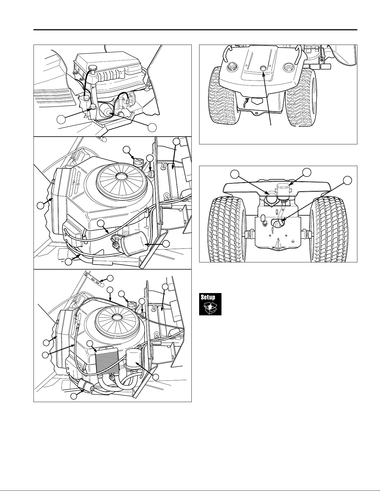
1. Add engine oil (engine is shipped dry). Oil recommendations are provided in the engine manual.
Check Transmission Oil Level
NOTE: Lift cylinder should be extended.
1. Locate the clear tube (B, Figure 11) and expansion
chamber (A) under the seat deck. Using a flashlight,
observe the oil level in the clear tube. 1” of oil should
be visible in the clear tube. DO NOT OVERFILL.
Empty space is required in the tube and expansion
chamber for heat expansion.
2. If necessary, remove the plug from the seat deck
(Figure 10), clean the area surrounding the expansion
chamber (A, Figure 11), remove the cap, and add oil.
D
C
B
A
E
G
F
Figure 9. Engine Compartment Liquid Cooled (Top) & Air Cooled (Bottom)
A. Battery F. Throttle Cable
B. Oil Filter G. Choke Cable
C. Air Filter H. Hood Strap
D. Oil Fill/Dipstick I. Oil Cooler
E. Fuel Filter
Figure 11. Hydraulic System Oil Filter
A. Expansion Chamber C. Hydraulic Oil Filter
B. Clear Tube
B
A
A
Figure 10. Seat Deck Access Plug
Expansion Chamber
Access Plug
LIQUID COOLED V-TWIN
B
D
G
D
I
H
C
E
A
E
G
F
B
Page 10

Landlord / 1700 / 2700 Series
TP 300-2226-02-LL-SMA
1/20018
Check Fluid Levels continued…
Engine Coolant (Kawasaki Models)
The engine coolant level and quality should be checked
before each use, when the engine is off and cool.
1. Check coolant in the overflow reservoir (C, Figure
12). Coolant should be green in color and coolant
level should be between the “H” and “L” marks on the
tank.
2. If the coolant level is below the “L” mark on the overflow reservoir, then with the engine off and cool,
remove the radiator cap (D, Figure 12). Add coolant
(50/50 mixture of ethylene glycol antifreeze and distilled water), slowly fill the radiator to the bottom of
the radiator cap filler neck.
3. Inspect for leaks in system as described on the next
section. Run the engine until it reaches normal operating temperature and recheck the coolant reservoir
level.
Inspect Cooling System
(Kawasaki Models)
Inspect the radiator and the hoses.
1. Inspect radiator inlet and outlet tubes for cracks,
kinks, dents, and fractured seams. Have radiator
repaired or replaced if necessary.
2. Check for dirt and insects that may be lodged in the
radiator. Clean them out using compressed air or a
low-pressure washer.
LIQUID COOLED V-TW
IN
Figure 12. Engine Compartment (View from Right)
A. Rubber Strap D. Radiator Cap
B. Oil Filter E. Oil Fill/Dipstick
C. Overflow Reservoir
A
B
C
E
D
Figure 13. Checking Tire Pressure
Tire Pressure
Front 12-15 psi (83-104 kPa)
Rear 6-8 psi (41-55 kPa)
WARNING
Engine coolant contains ethylene glycol and is
harmful or fatal if swallowed. Avoid contact with
eyes, skin, and clothing. Store in tightly closed
containers. Wash thoroughly after handling. Follow
safety guidelines on coolant container labels.
Reduce & Check Tire
Pressures
The tires are over-inflated for shipping purposes. Inflate
to the pressures shown. Note that these pressures may
differ slightly from the “Max Inflation” stamped on the
side-wall of the tires. The pressures shown provide proper traction, improve cut quality, and extend tire life.
Page 11

Landlord / 1700 / 2700 Series
1/2001 9
TP 300-2226-02-LL-SMA
Lubrication
Lubricate the unit at the locations shown in Figures 14
through 18 as well as the following lubrication points.
Grease:
• front axle pivot
• front wheel bearings
• front axle grease fittings
• steering linkage
• foot pedal
• mower pivots
• mower arbors
• transmission idler assembly pivot
• rear axle shafts (remove wheel hubs)
Use grease fittings when present. Disassemble parts
to apply grease to moving parts when grease fittings
are not present.
Not all greases are compatible. Simplicity Lithium
Grease is recommended, automotive-type lithium
grease may be used when this is not available.
Oil:
• hydro linkage
• seat adjustment assembly
• brake linkage
• frame pivot points
• mower deck height adjustment linkage
• manual lift lever
Generally, all moving metal parts should be oiled
where contact is made with other parts. Keep oil and
grease off belts and pulleys. Remember to wipe fittings and surfaces clean both before and after lubrication.
Figure 16. Brake Pedal Pivot Point
Figure 14. Lubricate Steering Linkage
Figure 15. Lubricating the Tractor
Page 12

Landlord / 1700 / 2700 Series
TP 300-2226-02-LL-SMA
1/200110
Lubrication continued…
Figure 18. Mower Lubrication Points
Figure 17. Arbor Lubrication Points
Lubricate Rear Axle Shafts
NOTE: This section has been included for reference purposes only. It does not need to be performed as part of
new unit setup.
We recommend removing the rear wheel hubs and lubricating the axle shafts yearly. This prevents the wheel
hubs from seizing onto the axle shafts and makes future
service easier.
1. Turn off the ignition, turn off the PTO, engage the
parking brake, and block the front tires.
2. Using a jack or chain hoist positioned at the center of
the rear frame, carefully jack the unit up until the rear
tires are approximately 1"- 2" off the ground.
NOTE: For overall unit stability during service, do not
jack rear end higher than required for wheel removal.
3. Support the rear of the unit on jackstands positioned
under the rear frame.
NOTE: Your axle assembly may differ slightly from the
assembly pictured: the quantity of washers (G, Figure
19) may be one or two. This is adjusted on a tractor by
tractor basis during assembly to allow a small amount of
axle end-play.
4. Remove the wheel bolts (J, Figure 19) and wheels
(E).
5. Remove the plastic hub cap (I).
6. Remove E-ring (H) using a screwdriver.
7. Remove the washers (G), hub cap retainer (F), and
wheel hub (D). Remove the key (C).
8. Lubricate the axle shaft with anti-seize compound or
lithium grease.
9. Reinstall the components in reverse order of disassembly and lower the unit. Be sure the key (C) is in
place in the axle keyway.
A
B
C
D
E
F
G
H
I
J
Figure 19. Rear Axle Assembly
A. Anti-Rotation Washer G. Small Washers
B. Large Washers (As Required)
C. Key H. E-Ring
D. Wheel Hub I. Hub Cap
E. Wheel & Tire Assy. J. Capscrew
F. Hub Cap Retainer
Page 13

Landlord / 1700 / 2700 Series
1/2001 11
TP 300-2226-02-LL-SMA
Mower
Assembly
Figure 22. Mower Hitch Assembly - 44” & 50” Mowers
A. Leveling Rod D. Spacer
B. Flat Washer E. Mower Hitch
C. Capscrew F. Locknut
WARNING
Mower blades are sharp. For your personal
safety, do not handle mower blades with bare
hands. Careless or improper handling of blades
may result in serious injury.
E
A
BC
D
F
Torque Mower Blades
44” & 50” MODELS
1. Reinstall each blade with the tabs pointing up toward
deck as shown in Figure 20. Secure with a capscrew,
spring washer and hex washer (be certain the hex
washer is aligned with the hex shaft). Use a wooden
block to prevent blade rotation and torque capscrews
to 45-55 ft.lbs. (61-75 N.m.).
54” MODELS
1. Reinstall each blade with the tabs pointing up toward
deck as shown in Figure 21. Secure with a capscrew,
spring washer and spline washer (be certain the
spline washer is aligned with the shaft). Use a wooden block to prevent blade rotation and torque capscrews to 45-55 ft.lbs. (61-75 N.m.).
WARNING
For your personal safety, blade mounting
capscrews must each be installed with a hex
washer and spring washer, then securely
tightened. Torque blade mounting capscrew to
45 - 55 ft. lbs. (61 - 75 N.m.)
Figure 20. Installing The Blade - 44” & 50” Models
A. 4x4 Wood Block C. Spring Washer
B. Hex Washer D. Blade Bolt
Figure 21. Installing The Blade - 54” Models
A. 4x4 Wood Block C. Spring Washer
B. Spline Washer D. Blade Bolt
Hitch & Leveling Rod Assembly
1. Remove the hardware (B, C, D, F, Figure 22) from
mower leveling rod (A) and flip hitch (E) over from the
shipping position.
2. Reinstall the leveling rod (A) in the bottom hitch hole
using the hardware removed in step one. Install the
hardware as shown in Figure 22.
IMPORTANT NOTE
DO NOT REMOVE THE MOWER DECK
BAFFLES. The baffles help prevent grass
clippings from becoming airborne and plugging up the engine cooling grates. Plugged
cooling grates can cause engine over-heating and create a potential fire hazard.
Mower Deck Baffles
(Liquid Cooled Models)
B
A
TIGHTEN
C
D
B
A
TIGHTEN
C
D
Page 14

Landlord / 1700 / 2700 Series
TP 300-2226-02-LL-SMA
1/200112
Figure 25. Mower Hitch
A. Tractor Hitch Brackets
B. Spring-Loaded Lever
FIgure 24. Hitch Hardware - 54” Models Only
A. Hitch Rod C. Safety Clips
B. Right Leveling Rod D. Left Leveling Rod
A
B
C
D
C
A
Figure 23. Raising & Lowering Mower
A. Mower Lift Lever
B. Mower Height Adjuster
B
A
WARNING
Engage parking brake, disengage PTO, stop
engine and remove key before attempting to
install or remove the mower.
Muffler and surrounding areas may be hot.
Installing the Mower Deck - All Hydraulic
Lift Models & 44” Manual Lift Models
NOTE: Perform mower installation on a hard, level surface such as a concrete floor.
1. Park the tractor, fully lower the attachment lift, turn
off the PTO switch, turn off the engine, remove the
key, and engage the parking brake. Turn the wheels
fully to the left.
2. Place mower in the lowest cutting position using the
mower height adjuster (B, Figure 23). Slide the
mower deck under the right side of tractor so that the
mower hitch is aligned with front tractor hitch (A,
Figure 25).
54” MODELS ONLY
3. After sliding the mower under the tractor, install the
hitch rod (A, Figure 24) and leveling rods (B, D).
Secure with washers and clips (C).
ALL MODELS
3. See Figure 25. Turn wheels straight. Pull back on
the spring-loaded lever (B) while lifting up on the
mower hitch. Install the mower hitch onto tractor hitch
brackets (A). When properly installed, the springloaded lever should seat fully underneath the brackets (A).
A
B
Page 15

Landlord / 1700 / 2700 Series
1/2001 13
TP 300-2226-02-LL-SMA
Figure 28. Mower Lift - 50” Manual Lift Models
A. Bow Tie Clip
B. Clevis Pin (Inserted Left to Right)
C. Lift Cable
D. Clevis Pin (Inserted Right to Left)
E. Bow Tie Clip & Washer
F. Mower Lift Arm
C
B
D
A
E
F
Figure 26. Mower Lift - Hydraulic Lift Models & 44”
A. Mower Lift Chain, R.H. E. Mower Lift Chain, L.H.
B. Tractor Lift Arm F. Clevis Pin, Short
C. Clevis Pin, Long G. Washer
D. Safety Clip
L.H. Side
R.H. Side
Figure 27. Removing & Installing Belt
A. Idler Arm
B. PTO Pulley
FRONT
4. See Figure 26. Connect the mower lift chains (A & E)
to the the tractor lift arm (B) using the clevis pins,
washers and safety clips. Install the shorter clevis pin
(F) on the left side as shown.
5. See Figure 27. From left side of tractor, use the idler
arm (A) to relieve belt tension. Install belt onto the
PTO pulley (B).
54” MODELS ONLY
6. Raise the attachment lift and rotate the front gauge
wheels (Figure 29) into cutting position.
Installing the Mower Deck 50” Manual Lift Models
1. Park the tractor, fully lower the attachment lift, turn off
the PTO switch, turn off the engine, remove the key,
and engage the parking brake. Turn the wheels fully
to the left.
2. Place mower in the lowest cutting position using the
mower height adjuster (B, Figure 23). Slide the mower
deck under the right side of tractor so that the mower
hitch is aligned with front tractor hitch (A, Figure 25).
3. See Figure 25. Turn wheels straight. Pull back on
the spring-loaded lever (B) while lifting up on the
mower hitch. Install the mower hitch onto tractor hitch
brackets (A). When properly installed, the springloaded lever should seat fully underneath the brackets (A).
4. See Figure 28. Connect the mower lift cable (C) to
the mower lift arm (F) using a clevis pin (D), bow tie
clip and washer (E).
IMPORTANT NOTE: For both lift cables, the mower clevis pin (D) is installed from right to left; the tractor lift clevis pin (B) is installed from left to right. The pins must be
installed in this orientation for proper clearance.
5. See Figure 27. From left side of tractor, use the idler
arm (A) to relieve belt tension. Install belt onto the
PTO pulley (B).
D
C
B
F
G
D
A
E
B
A
Page 16

Landlord / 1700 / 2700 Series
TP 300-2226-02-LL-SMA
1/200114
Gauge Wheels (54” Models)
The mower gauge wheels can be placed in two positions
depending on the height of cut. When using higher cutting heights, set the wheels in the lower position. When
using lower cutting heights, set the wheels in the upper
position. To adjust:
1. Remove the hair pin clip (A, B, Figure 29).
2. For upper position, install the pin (A) through the spindle above the bracket (C). For the lower position,
push down on the top of the spindle, and install the
hair pin clip (B) below the top of the bracket (C).
Figure 29. Gauge Wheel Adjustment
A. Hair Pin (Upper Position)
B. Hair Pin (Lower Position)
C. Gauge Wheel Bracket
A
B
C
Page 17

Landlord / 1700 / 2700 Series
1/2001 15
TP 300-2226-02-LL-SMA
Leveling
Mower Deck
Side-to-Side Leveling
1. Check the tires pressures. Refer to Check and
Reduce Tire Pressures.
2. Park the tractor on a level surface. Point tires straight
ahead.
3. Make sure mower lift is in the down position. Place
height adjuster in mid-cut position.
4. Turn the outside blades side-to-side and measure distance from outside tips of blades to ground.
Measurements should be within 1/8 inch of each
other. For adjustment, refer to Figure 30.
a. Loosen outside nut (A, Figure 30).
b. Turn eccentric hex nut (B) to raise or lower left
hand side of mower.
c. Hold nut (B) and tighten nut (A) to 30 ft. lbs. Recheck measurement.
NOTE: 44” & 50” Mowers. When using a turbo collection
system, raise the discharge side of the mower approximately 1/4” (6mm) to compensate for turbo assembly
weight. Check the level of the cut grass and adjust the
1/4” (6mm) measurement as necessary for a smooth,
even cut.
Front-to-Back Leveling
Turn the blades front-to-back. Measure the distance
from the ground to front tip of center blade, and from
ground to rear tips of left hand and right hand blades.
Front tips should be 1/8"-1/4" (3-6 mm) higher than rear
tips. For adjustment, refer to Figure 31.
1. Check the tires pressures. Refer to Check and
Reduce Tire Pressures.
2. To raise front of mower deck, loosen front nut (A) and
turn rear nut (B) against bracket (C) to shorten rod (D).
3. To lower front of mower deck, loosen rear nut (B) and
bracket (C) will move back to lengthen rod (D).
4. Recheck measurement before tightening front nut (A)
against bracket.
NOTE: 54” mowers have two adjustment rods (D, Figure
31) that should be adjusted simultaneously.
B
A
Figure 30. Side-to-Side Leveling
A. Outside Nut B. Eccentric Nut
A
B
C
D
Figure 31. Front-to-Back Leveling
A. Front Nut C. Mower Bracket
B. Rear Nut D. Adjustment Rod
WARNING
Before checking mower, shut off electric clutch
and engine. Allow all moving parts to stop.
Remove ignition key.
Page 18

Landlord / 1700 / 2700 Series
TP 300-2226-02-LL-SMA
1/200116
Figure 32. Seat Switch
A. Seat Switch B. Wiring Harness
Perform
Safety Checks
Functional Tests
1. Check the tractor for loose bolts, screws, nuts, etc.
2. Start the engine and check all controls for proper
operation: ground speed control pedals, clutch/brake
pedal, parking brake, throttle and choke cables, electric PTO clutch, headlight switch, steering, attachment
lift, etc.
3. Stop the engine and check for fluid leaks: oil, gasoline, coolant, or transmission oil.
4. If any control fails to operate properly during testing or
seems to be out of adjustment, check and readjust it
according to the following Adjustments section.
Dash Safety Lights Test
Check the operation of the tractor controls and dash
safety lights. With an operator in seat and ignition switch
turned to ON (engine not running):
1. PTO Indicator Light (red) should go on and off with
operation of electric clutch switch.
2. The parking brake / cruise control lock light should go
on when the parking brake / cruise control is activated.
3. Headlight Indicator Light should go on when the
headlights are turned on.
4. Oil Pressure Indicator Light (red) should turn on and
should go out immediately after the engine starts.
5. Liquid Cooled Models Only - Engine Overheat
Indicator Light should go on when the starter is
cranked and should go out immediately after the
engine starts. If the engine overheats, the indicator
light will flash.
Mower Blade Stopping Check
Mower blades and mower drive belt should come to a
complete stop within five seconds after the electric clutch
switch is turned off.
With the tractor in neutral, the electric clutch switch disengaged, and an operator in the seat, start the tractor
engine. Run the engine at full throttle. Engage the electric
PTO clutch switch and wait several seconds. Disengage
electric clutch switch and check the time it takes for the
mower drive belt to stop.
If the mower drive belt does not stop within five seconds,
adjust the PTO clutch according to the instructions in the
Electric Clutch Adjustment section.
Seat Switch Connection
Check that the seat switch (A, Figure 32) is connected to
the seat switch wire harness (B).
WARNING
Disengage the PTO, stop the engine, set the parking
brake, and wait for moving parts to stop before leaving operator's position for any reason.
If the tractor does not pass the test, do not operate tractor. Under no circumstance should you
attempt to defeat the purpose of the safety
system.
A
B
Page 19

Landlord / 1700 / 2700 Series
1/2001 17
TP 300-2226-02-LL-SMA
Burnishing the Electric
PTO Clutch
1. Select a safe area to operate the mower deck. With
the drive in neutral, the PTO switch disengaged, and
an operator in the seat, start the tractor engine. Run
the engine at full throttle.
2. Engage the PTO switch and run the deck for fifteen
seconds. Disengage the PTO switch and wait for the
mower drive belt to stop.
3. Repeat step 2 above ten times, and then re-check the
mower blade stopping time. (Stopping time must be
five seconds or less.)
SAFETY INTERLOCK
SYSTEM TESTS
This unit is equipped with safety interlock switches
and other safety devices. These safety systems are
present for your safety: do not attempt to bypass
safety switches, and never tamper with safety
devices. Check their operation regularly.
Operational SAFETY Checks
Your unit is equipped with a seat switch safety system. Check the seat switch operation every fall and
spring with the following tests.
Test 1 — Engine should NOT crank if:
• PTO switch is ON, OR
• Brake pedal is NOT fully depressed (parking
brake OFF).
Test 2 — Engine SHOULD crank if:
• PTO switch is OFF, AND
• Brake pedal is fully depressed
(parking brake ON).
Test 3 — Engine should SHUT OFF if:
• Operator rises off seat with PTO engaged, OR
• Operator rises off seat with brake pedal NOT
fully depressed (parking brake OFF).
Test 4 — Blade Brake Check
Mower blades and mower drive belt should come to
a complete stop within five seconds after electric
PTO switch is turned OFF (or operator rises off
seat). If mower drive belt does not stop within five
seconds, readjust the PTO clutch as described in
the ADJUSTMENTS section or see your dealer.
NOTE: Once the engine has stopped, the PTO
switch must be turned off after the operator returns
to the seat in order to start the engine.
WARNING
If the unit does not pass a safety test, do not
operate it. See your authorized dealer. Under
no circumstance should you attempt to
defeat the purpose of the safety interlock
system.
Page 20

Landlord / 1700 / 2700 Series
TP 300-2226-02-LL-SMA
1/200118
Electric PTO Clutch
Adjustment
Check the PTO clutch adjustment after the initial 50 hour
break-in period and then after every 250 hours of operation. Also perform the following procedure if the clutch is
slipping or will not engage.
1. Remove key from ignition switch and disconnect
spark plug wires to prevent the possibility of accidental starting while the PTO is being adjusted.
2. See Figure 33. Note the position of the 3 adjustment
windows (A) in the side of the brake plate and the
nylock adjustment nuts (B).
3. Insert a .012” feeler gauge through each window,
positioning the gauge between the rotor face and the
armature face as shown in Figure 34.
4. Alternately tighten the adjustment nuts (B, Figure 33)
until the rotor face and armature face just contacts the
gauge.
5. Check the windows for an equal amount of tension
when the gauge is inserted and removed, and make
any necessary adjustments by tightening or loosening
the adjustment nuts.
NOTE: The actual air gap between the rotor and armature may vary even after performing the adjustment procedure. This is due to dimensional variations on component parts, and is an acceptable condition.
6. Check the mower blade stopping time. The mower
blades and mower drive belt should come to a complete stop within five seconds after the electric PTO
switch is turned off (see MOWER BLADE STOPPING
CHECK, Page 16).
Figure 33. PTO Clutch Adjustment
A. Adjustment Window (Qty. 3, one shown)
B. Adjustment Nuts
Window
Adjustment
Nut
Figure 34. Feeler Gauge Position
.012”
Feeler
Gauge
(3) Req’d
Steering Gear
Adjustment
If there is excessive slack in the steering system, the steering
gear can be moved closer to the steering shaft gear.
1. Loosen the two nuts (Figure 35)
2. Push the bracket so that the gear teeth are closely
meshed.
3. Retighten the nuts after adjustment.
A
B
B
B
Figure 35. Steering Gear Adjustment
Nuts
Page 21

Landlord / 1700 / 2700 Series
1/2001 19
TP 300-2226-02-LL-SMA
Brake Spring
Adjustment
1. Disengage the PTO, stop the engine, block the
wheels, remove the ignition key, and engage the
parking brake.
2. Remove the mower deck (see Mower Deck Removal).
3. Locate the brake spring (A, Figure 36) and adjustment nut (B).
4. With the parking brake engaged, measure the compressed spring length. The spring should be 5-3/8” to
5-3/4” when compressed.
If the spring is not within this range, turn the adjustment nut (B, Figure 36) to compress or release the
spring.
If this adjustment does not correct a braking problem,
and the brake linkage is not at fault; the internal braking mechanism inside the transmission will require
service.
Foot Pedal Height
Adjustment
(Forward Speed Adjustment)
1. Disengage the PTO, stop the engine, block the
wheels, and remove the ignition key. DO NOT
engage the parking brake.
2. Measure the distance between the bottom of the
ground speed control pedal and the foot rest. There
should be 2-1/2” clearance (Figure 37). If not, proceed to step 3.
NOTE: If desired, the right rear wheel can be removed for
easier access to the transmission.
3. Loosen the carriage bolt (C, Figure 38) securing the
foot pedal rod (A) to the transmission control arm (B).
4. Place a 2-1/2” thick wood block under the forward
ground speed pedal. While holding the pedal against
the wood block, tighten the carriage bolt (C).
Figure 38. Foot Pedal Adjustment
A. Foot Pedal Rod C. Carriage Bolt
B. Transmission Control Arm
Figure 37. Foot Pedal Height Measurement
A
C
B
2-1/2”
Figure 36. Brake Spring Adjustment
A. Brake Spring B. Adjustment Nut
A
B
Page 22

Landlord / 1700 / 2700 Series
TP 300-2226-02-LL-SMA
1/200120
Internal
Neutral Adjustment
The neutral gate of the Tuff Torq K71 is established internally and should not need to be adjusted. If the tractor
creeps forward or backward with the ground speed control pedals at rest (neutral position) while the engine is
running, perform the following adjustment:
1. Block the front tires.
2. Using an overhead chain hoist or hydraulic floor jack,
elevate the rear end of the tractor so that the wheels
do not contact the ground. Position jackstands under
the rear frame.
3. Using a 17 mm wrench loosen the neutral adjustment
jam nut (A, Figure 40).
4. Activate the seat switch, depress the brake pedal,
and start the engine.
5. Release the brake pedal.
6. Using an 8 mm wrench adjust neutral by turning the
eccentric (B, Figure 40) until the rear wheels do not
creep.
Figure 40. Right Side of Transmission
A. Jam Nut B. Eccentric
Cruise Control
Release Adjustment
See Figure 39.
1. Stop the tractor, shut off the PTO, turn off the engine,
and remove the key. DO NOT engage the parking
brake.
2. Remove the mower deck.
3. Fully depress the forward ground speed control pedal
and engage the cruise control.
4. Locate the cruise control release tabs (A) on the
brake cam (B) and cruise lock cam (C).
With the cruise control locked and the brake pedal at
rest (disengaged) there should be 1/8” to 3/16” clearance between the two tabs. If not, proceed to step 5.
Depressing the brake pedal approximately 1” to 1-1/4”
should cause the cams to contact each other releasing the cruise control. If not, proceed to step 5.
5. Loosen the cam adjustment bolt (D) and rotate the
cruise lock cam (C) until there is 1/8” gap between the
cruise release tabs (A).
Repeat step 4.
Figure 39. Cruise Control Release Tabs
A. Cruise Release Tabs C. Cruise Lock Cam
B. Brake Cam D. Cam Adj. Bolt
A
B
C
D
7. Once neutral has been established, hold the eccentric
(B) in place and secure in position with the jam nut
(A).
8. Fully depress both the forward ground speed pedal
and reverse ground speed pedal and check that it
returns to neutral and the rear wheels do not creep.
9. After adjustments have been completed, shut off the
engine and lower the tractor.
10. Perform FOOT PEDAL HEIGHT ADJUSTMENT procedure (see Page 19).
NOTE: Idler
Assembly
Removed for
Illustration
Purposes.
1/8” to 3/16”
Gap
B
A
Page 23

Transmission
Maintenance
There are several maintenance procedures that must be
performed on the transmission after the first 50 hours of
operation and then after every 250 hours.
Transmission Service Information
Transmission Oil Capacity: Apx. 4-1/2 Quarts
Transmission Oil Type: SAE 10W-30 with a minimum
API rating of SG/CD.
Internal Oil FIlter Part Number: 1719832
Hydraulic System Oil Filter Part Number: 1719168
Landlord / 1700 / 2700 Series
1/2001 21
TP 300-2226-02-LL-SMA
Differential Lock
Cable Adjustment
(Select Models)
1. Stop the tractor, shut off the PTO, turn off the engine,
remove the key, and engage the parking brake.
2. Check the position of the diff. lock pedal. The top of
the pedal should be even with the top of the frame
tunnel as shown in Figure 41. Also check the diff.
lock cable. With the pedal at rest there should be no
tension on the cable except the weight of the pedal. If
required, adjust the pedal as follows.
3. Loosen the adjustment nuts (A, Figure 42) and move
the cable sheath until the pedal is at the proper height
(See Figure 41).
4. Tighten the adjustment nuts, and repeat step 2.
Figure 42. Adjust Diff. Lock Cable
A. Adjustment Nuts
Do not allow dirt, water, or other debris to
enter the expansion chamber or
transmission. Even a small amount of dirt
can damage the transmission
Check Transmission Oil Level
Service Interval: Every 5 Hours
NOTE: Lift cylinder should be extended.
1. Locate the clear tube (C, Figure 44) and expansion
chamber (D) under the seat deck. Using a flashlight,
observe the oil level in the clear tube. 1” of oil should
be visible in the clear tube. DO NOT OVERFILL.
Empty space is required in the tube and expansion
chamber for heat expansion.
2. If necessary, remove the plug from the seat deck
(Figure 43), clean the area surrounding the expansion
chamber (D, Figure 44), remove the cap, and add oil.
Figure 41. Differential Lock Pedal Height
A
IMPORTANT NOTE
DO NOT ADJUST THE CABLE SO TIGHT
AS TO REMOVE ALL CABLE SLACK. This
will partially engage the differential lock and
damage the transmission. There must be a
small amount of slack in the cable
Rear Wheel Removed
for Clarity
Top of Pedal
Should Be Even
with Top of Frame
Page 24

Landlord / 1700 / 2700 Series
TP 300-2226-02-LL-SMA
1/200122
Figure 46. Internal Transmission Filter Service
A. Plastic Plug B. Internal Filter
Figure 45. Transmission Drain Plugs
A. 14mm Drain Plugs
Figure 44. Hydraulic System Oil Filter
A. Hydraulic System Filter C. Clear Tube
B. Differential Fill Cap D. Expansion Chamber
A
B
C
D
A
B
Figure 43. Seat Deck Access Plug
Expansion Chamber
Access Plug
Change Transmission Oil, Internal
Filter, & Hydraulic System Filter
Service Interval: After 50 Hrs, Then Every 250 Hrs
The oil should also be changed whenever it has become
discolored from overheating or contamination.
1. Place a drain pan under the transmission and remove
the two 14mm drain plugs (A, Figure 45).
2. Remove the differential fill cap (B, Figure 44).
3. Remove the plastic plug (A, Figure 46).
4. Remove and replace the hydraulic system filter (A,
Figure 44). Thread the new filter onto the filter base
and tighten 1/2-3/4 turns past finger tight.
5. Remove and replace the internal transmission filter
(B, Figure 46).
6. Reinstall the plastic plug (A, Figure 46) and the two
14mm drain plugs (A, Figure 45).
7. Using a long funnel, add 2 quarts of oil to the differential fill (the differential fill cap B, Figure 44 should have
been removed earlier).
8. Reinstall the differential fill cap (B, Figure 44).
9. Remove the expansion chamber access plug (Figure
43) and expansion chamber cover. Add 2 quarts of
oil to the expansion chamber (D, Figure 44) a few
ounces at a time.
10. Reinstall the expansion chamber cover (D, Figure 44).
11. Test run the tractor for 10 minutes. Drive forward and
backward; raise and lower the attachment lift several
times.
12. Recheck the transmission oil level with the cylinder
extended. There should be 1” of oil visible in the
clear plastic tube (C, Figure 44).
Do not allow dirt, water, or other debris to
enter the expansion chamber or
transmission. Even a small amount of dirt
can damage the transmission
A
Page 25

Landlord / 1700 / 2700 Series
1/2001 23
TP 300-2226-02-LL-SMA
Transmission Drive Belt
Replacement
NOTE: Be sure to use only genuine Simplicity replacement parts. Check the back of this manual or the decal
under the hood for common replacement part numbers.
REMOVE THE OLD BELT
1. Turn off the PTO, stop the engine, block the tires, and
engage the parking brake.
2. Remove the mower deck.
3. Remove the transmission belt guide (C).
4. Loosen the idler pulleys (B, Figure 47).
5. Disconnect the steering arm (E) from the drag link.
6. Unplug the PTO clutch electrical plug (A). Remove
the capscrew (F) securing the PTO clutch to the
crankshaft. Remove the clutch.
7. Remove the drive belt from the engine pulley, idler
pulleys, and transmission input pulley.
INSTALL THE NEW BELT
8. Install a new drive belt on the transmission input pulley and engine drive pulley.
9. Install the PTO clutch using the original hardware.
Torque the crankshaft bolt (F) to 45-50 ft lbs.
10. Install the drive belt in the idler assembly pulleys (B).
Tighten the pulley hardware.
11. Install the transmission belt guide (C).
12. Release the parking brake. Check that the belt has
been routed correctly and that all adjustable belt
guides are adjusted to within 1/8” of the belt guide.
13. Reconnect the steering arm (E) and drag link. Coat
the steering arm capscrew with thread locking compound and torque to 17-23 ft. lbs.
Figure 47. Transmission Drive Belt Replacement
A. PTO Clutch Plug D. Idler Assy. Spring
B. Idler Pulleys E. Steering Arm
C. Trans. Belt Guide F. Crankshaft Bolt
D
E
C
A
F
B
Page 26

Landlord / 1700 / 2700 Series
TP 300-2226-02-LL-SMA
1/200124
Mower Belt Replacement
To avoid damaging belts, DO NOT PRY
BELTS OVER PULLEYS.
Figure 48. Mower Belt Routing
A. Idler Pulley Arm C. Belt Guide (44” & 50” Only)
B. PTO Clutch Pulley D. Arbor Drive Pulley
Figure 49. Mower Deck - 44" & 50” Mowers
A. Capscrew
B. Right-hand Arbor Cover
C. Spring
D. Left-hand Arbor Cover
1/8” Gap
FRONT
A
D
B
C
44” & 50” PTO Belt Replacement
1. Park the tractor on a smooth, level surface such as a
concrete floor. Disengage the PTO, turn off the
engine and lock the parking brake. Remove the key.
Remove the mower or place in the lowest cutting
position.
2. Move the idler arm (A, Figure 48) to relieve belt tension. Drop the belt from the PTO (electric clutch) pulley.
IMPORTANT: Note the position of all belt guides relative
to the belt and pulleys before loosening.
3. Loosen the nut and lockwasher securing idler pulley
belt guide (C, Figure 48).
4. See Figure 49. Remove three capscrews securing
left-hand arbor cover (D).
5. Remove the old belt and replace with a new one.
Make sure the V-side of belt runs in the pulley
grooves.
6. See Figure 48. Position the idler pulley belt stop (C)
in its original position so that there is a 1/8" (3mm)
gap between the pulley and belt stop.
7. See Figure 49. Reinstall the left-hand arbor cover
(D). Reinstall the mower deck if removed.
8. Run the mower under a no-load condition for about 5
minutes.
54” PTO Belt Replacement
1. Park the tractor on a smooth, level surface such as a
concrete floor. Disengage the PTO, turn off the
engine and lock the parking brake. Remove the key.
2. Move the idler arm (A, Figure 48) to relieve belt tension. Drop the belt from the PTO (electric clutch) pulley.
3. Remove the old belt and replace with a new one.
Make sure the V-side of belt runs in the pulley
grooves.
4. Install the drive belt on the PTO pulley. Move the
idler arm and install the belt on the idler pulley.
5. Run the mower under no-load condition for about 5
minutes.
B
C
A
D
Page 27

Landlord / 1700 / 2700 Series
1/2001 25
TP 300-2226-02-LL-SMA
FRONT
Figure 52. Mower Deck Drive Belt Routing All Models
A. Arbor Drive Pulley (V-sided)
B. Idler Pulley (Flat-sided)
A
A
A
B
Figure 51. Mower Deck - 54” Mowers
A. Taptite Screws
B. Right-hand Arbor Cover
C. Spring
D. Left-hand Arbor Cover
E. Alignment Notches
D
B
C
A
Figure 50. Mower Deck - 44" & 50” Mowers
A. Capscrew
B. Right-hand Arbor Cover
C. Spring
D. Left-hand Arbor Cover
E
E
B
A
D
C
A
Arbor Drive Belt Replacement -
All Models
NOTE: Be sure to use only genuine Simplicity replacement parts.
1. Park the tractor on a smooth, level surface such as a
concrete floor. Disengage the PTO, turn off the
engine and lock the parking brake. Remove the key.
2. Remove the mower from the tractor. See Mower
Removal in the Operation section.
44” &50” MODELS
3. Remove the capscrews securing the right-hand arbor
cover (B, Figure 50). Remove three capscrews securing left-hand arbor cover (D).
54” MODELS
3. Remove the PTO belt. Remove the taptite screws
(A, Figure 51) securing the belt covers and remove
the belt covers (B, D).
ALL MODELS
4. Using a pair of locking pliers or a spring puller,
remove the idler pulley spring (C, Figures 50, 51)
from slot in deck.
5. Loosen capscrew (A, Figure 50) securing the idler
pulley to the bracket. The belt can now be slipped
between the pulley and idler bracket hub.
6. Install a new belt as shown in Figure 52. Make sure
that V-side of belt runs in arbor pulley (A) grooves
and flat side of belt runs against idler pulley (B).
7. Tighten the capscrew (A, Figure 50).
8. Reinstall spring (C, Figures 50, 51) into its slot in
mower deck.
9. Reinstall the left and right arbor covers (B & D,
Figures 50, 51). 54” Models: To provide proper belt
cover clearance, make sure the alignment notches
(E, Figure 51) are centered on the taptite screws (A).
10. Install the mower onto the tractor.
Page 28

Landlord / 1700 / 2700 Series
TP 300-2226-02-LL-SMA
1/200126
MANUFACTURING INC.
500 N Spring Street / PO Box 997
Port Washington, WI 53074-0997 USA
© Copyright 2001 Simplicity Manufacturing, Inc.
All Rights Reserved. Printed in USA
NOTES
 Loading...