

Page 1
Attachment
g
Illustrated
Parts List
Attachment
. No. Description
Mf
1695299 54" Turbo Blower
MANUFACTURING, INC.
500 N. Spring Street / PO Box 997
Port Washington, WI 53074-0997 USA
www.simplicitymfg.com
© Copyright Simplicity Manufacturing, Inc. All Rights Reserved. Printed In USA.2007
Part No.:
TP 400-4530-00-AT-SMA
Rev.
1734809
04/2007
Page 2

Page 3

Table Of Content
s
PRODUCT COMPONENTS PAGES
Mower Driven Vac Group .....................................................................................................................................
Torque Specification Chart ..................................................................... Inside Back Cover
4
Page 4
Mower Driven Vac Group
NOTE: Unless noted otherwise,
use the standard hardware torque
specification chart.
987705
The above parts group applies to the following Mfg. Nos.:
1695299 - 54" Turbo Blower
Briggs and Stratton Yard Power Products Group
2007Copyright © by Briggs and Stratton Corporation
Milwaukee, WI, USA. All rights reserved
4
TP 400-4530-00-AT-SMA
Page 5

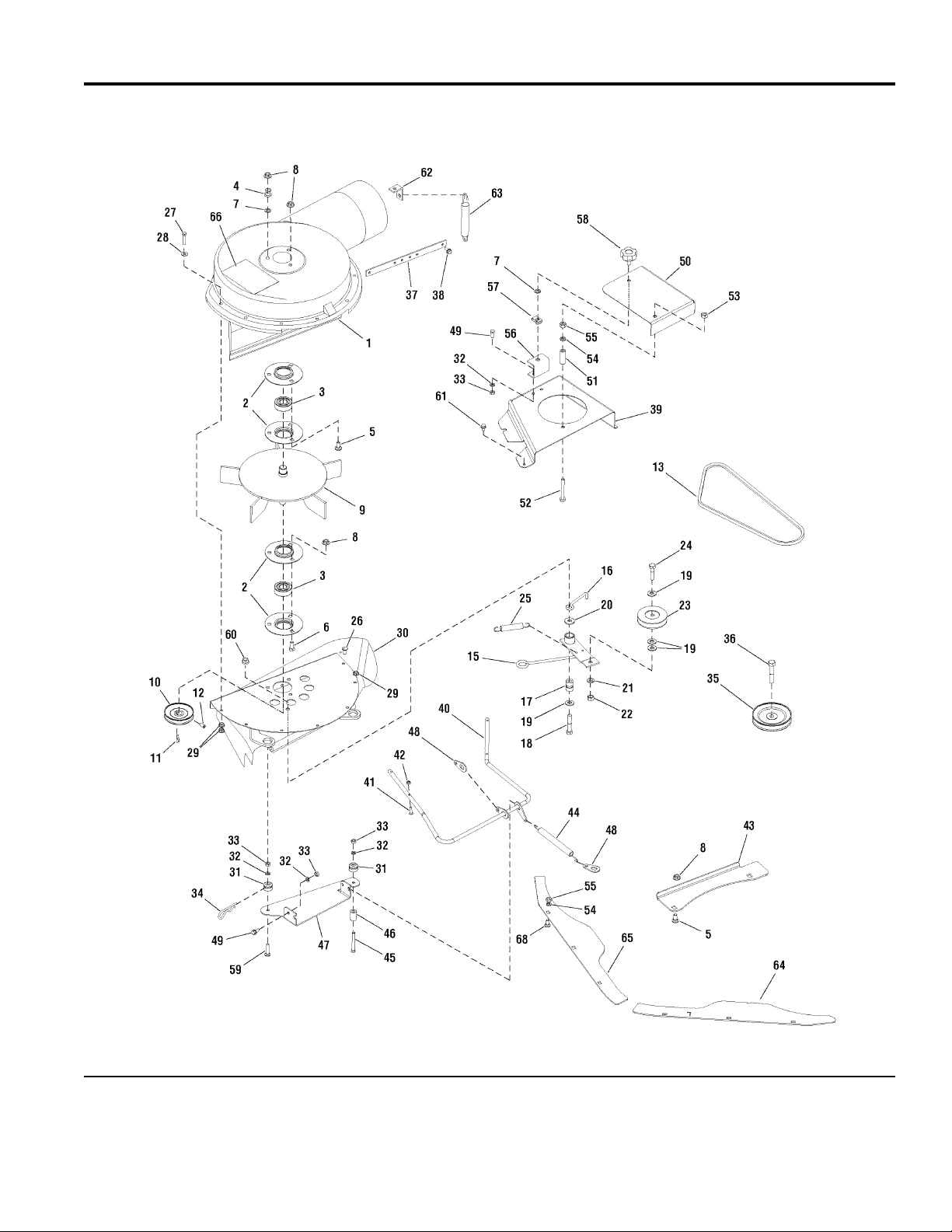
Mower Driven Vac Group
PART NO. DESCRIPTIONREF NO QTY.
Footnotes
TURBO HOUSING, Fan 1 1720742SM 1
RETAINER, Bearing 2 1665982SM 4
BEARING 3 2108202SM 2
"S" HOOK 4 1672689SM 1
BOLT, Carriage, 5/16 - 18 x 3/4 (Qty of 2 included in Ref. No. 69) 5 1931333SM 5
CAPSCREW, 5/16 - 18 x 3/4 6 1921332SM 3
PUSH NUT, 5/16 7 1933988SM 4
NUT, Flange Lock, 5/16 - 18 (Qty of 2 included in Ref. No. 69) 8 1927557SM 8
FAN ASSEMBLY 9 1706631ASM 1
PULLEY ASSEMBLY 10 1706634SM 1
KEY, Woodruff, #61 11 2860403SM 1
SCREW, Set Torx, 5/16 - 18 x 5/16 12 1960619SM 2
V-BELT, 3L 36.9 13 1720932SM 1
DECAL, Patent (Not shown, not serviceable) 14 ----- 1
IDLER ARM ASSEMBLY 15 1720934ASM 1
BELT STOP 16 1704419SM 1
BUSHING 17 1666114SM 1
CAPSCREW, 3/8 - 16 x 2 18 1923701SM 1
WASHER, 3/8 19 1924940SM 4
WASHER, 3/8 20 1922755SM 1
LOCKWASHER, Spring, 3/8 21 1916965SM 1
NUT, Hex, 3/8 - 16 22 1916950SM 1
PULLEY, Idler 23 2174561SM 1
CAPSCREW, Hex Head, 3/8 - 16 x 1-1/2, G5 24 1921969SM 1
SPRING, Extension 25 2174896SM 1
SCREW, Truss Head Phillips, 1/4 - 20 x 3/4 26 1935945SM 6
CAPSCREW, Hex Head, 1/4 - 20 x 1-1/4, G5 27 1921961SM 1
WASHER, 1/4 28 1921319SM 1
NUT, Hex Lock ESNA, 1/4 - 20 29 1920397SM 8
PLATE ASSEMBLY 30 1720721ASM 1
PIN, Pivot (Included in Ref. No. 69) 31 1720718SM 2
LOCKWASHER, Spring, 1/4 (Qty of 4 included in Ref. No. 69) 32 1916964SM 6
NUT, Hex, 1/4 - 20 (Qty of 4 included in Ref. No. 69) 33 1916622SM 6
CLIP, Hairpin 34 1704628SM 2
PULLEY ASSEMBLY (Included in Ref. No. 69) 35 1720737SM 1
CAPSCREW, Hex Head, 7/16 - 14 x 2-1/4, G8 (Included in Ref. No. 69) 36 1927120SM 1
STRAP 37 1706630ASM 1
SCREW, Hex Washer Head Taptite, 1/4 - 20 x 5/8 38 1927429SM 3
COVER, Arbor R.H. Turbo 39 1734303ASM 1
ROD & ANCHOR 40 1720951SM 1
SCREW, Truss Head Phillips, #10 - 24 x 3/4 (Included in Ref. No. 69) 41 1960404SM 4
NUT, Nylon Hex Lock, 10-24 (Included in Ref. No. 69) 42 1933896SM 4
PLATE, Support 43 1720749ASM 1
SPRING, Extension (Included in Ref. No. 69) 44 1719590SM 1
The above parts group applies to the following Mfg. Nos.:
1695299 - 54" Turbo Blower
Briggs and Stratton Yard Power Products Group
2007Copyright © by Briggs and Stratton Corporation
Milwaukee, WI, USA. All rights reserved
5
TP 400-4530-00-AT-SMA
Page 6

Mower Driven Vac Group
NOTE: Unless noted otherwise,
use the standard hardware torque
specification chart.
987705
The above parts group applies to the following Mfg. Nos.:
1695299 - 54" Turbo Blower
Briggs and Stratton Yard Power Products Group
2007Copyright © by Briggs and Stratton Corporation
Milwaukee, WI, USA. All rights reserved
6
TP 400-4530-00-AT-SMA
Page 7

Mower Driven Vac Group
PART NO. DESCRIPTIONREF NO QTY.
TAB, Locking (Included in Ref. No. 69) 48 1720921SM 3
CAPSCREW, Hex Head, 1/4 - 20 x 5/8 (Qty of 2 included in Ref. No. 69) 49 1921959SM 4
COVER 50 1720918ASM 1
SPACER 51 1713588SM 1
CAPSCREW, Hex Head, 5/16 - 18 x 2-1/2, G5 52 1921719SM 1
NUT, Hex Lock ESNA, 5/16 - 18 53 1919438SM 1
LOCKWASHER, Spring, 5/16 (Qty of 6 included in Ref. No. 69) 54 1917356SM 7
NUT, Hex, 5/16 - 18 (Qty of 6 included in Ref. No. 69) 55 1917372SM 7
BRACKET, "C" 56 1700654ASM 1
NUT, Speed, 5/16 - 18 57 1935255SM 1
KNOB, Plastic 58 1700669SM 1
BOLT, Carriage, 1/4 - 20 x 1-1/4 (Included in Ref. No. 69) 59 1931320SM 1
NUT, Hex Two-Way Lock Flange, 3/8 - 16 60 1930645SM 1
SCREW, Hex Washer Head Taptite, 1/4 - 20 x 3/8 (Included in Ref. No. 69) 61 1929000SM 2
BRACKET, "L" 62 1668500SM 1
SPRING, Extension 63 1727149SM 1
BAFFLE, Front L.H. 64 1720613ASM 1
BAFFLE, Front R.H. 65 1721023ASM 1
DECAL, Danger Thrown Objects 66 1700259SM 1
BOLT, Carriage, 5/16 - 18 x 3/4 (Included in Ref. No. 69) 68 1931332SM 6
HARDWARE BAG 69 1660617SM 1
INSTRUCTION MANUAL (Not shown) 70 1720927 1
Footnotes
The above parts group applies to the following Mfg. Nos.:
1695299 - 54" Turbo Blower
Briggs and Stratton Yard Power Products Group
2007Copyright © by Briggs and Stratton Corporation
Milwaukee, WI, USA. All rights reserved
7
TP 400-4530-00-AT-SMA
Page 8

Page 9

Page 10

Page 11

Hardware Identification & Torque Specifications
Common Hardware Types
Hex Head Capscrew
Carriage Bolt
Standard Hardware Sizing
When a washer or nut is identified as 1/2”, this is the
Nominal size
second number is present it represent the
When bolt or capscrew is identified as 1/2 - 16 x 2”, this
means the
second number represents the
example, and the final number is the
bolt or screw (in this example 2 inches long).
, meaning the
Nominal size
inside diameter
, or
body diameter
threads per inch
body length
Washer
Lockwasher
Hex Nut
is 1/2 inch; if a
threads per inch
is 1/2 inch; the
(16 in this
of the
The guides and ruler furnished below are designed to
help you select the appropriate hardware and tools.
0
1/4 3/4
1/2
Nut, 1/2”
Inside
Diameter
1
1/4 3/4
1/2
Screw, 1/2 x 2
2
1/4 3/4
1/2
3
1/4 3/4
1/2
4
Body
Diameter
Body
Length
Torque Specification Chart
FOR STANDARD MACHINE HARDWARE (Tolerance ± 20%)
Hardware
Grade
Size Of
Hardware ft/lbs Nm. ft/lbs Nm. ft/lbs Nm.
8-32
8-36
10-24
10-32
1/4-20
1/4-28
5/16-18 11 15.0 17 23.1 25 34.0
5/16-24 12 16.3 19 25.8 27 34.0
3/8-16 20 27.2 30 40.8 45 61.2
3/8-24 23 31.3 35 47.6 50 68.0
7/16-14 30 40.8 50 68.0 70 95.2
7/16-20 35 47.6 55 74.8 80 108.8
1/2-13 50 68.0 75 102.0 110 149.6
1/2-20 55 74.8 90 122.4 120 163.2
9/16-12 65 88.4 110 149.6 150 204.0
9/16-18 75 102.0 120 163.2 170 231.2
5/8-11 90 122.4 150 204.0 220 299.2
5/8-18 100 136 180 244.8 240 326.4
3/4-10 160 217.6 260 353.6 386 525.0
3/4-16 180 244.8 300 408.0
7/8-9 140 190.4 400 544.0 600 816.0
7/8-14 155 210.8 440 598.4 660 897.6
1-8 220 299.2 580 788.8 900 1,244.0
1-12 240 326.4 640 870.4 1,000 1,360.0
1. These torque values are to be used for all hardware
excluding: locknuts, self-tapping screws, thread forming
screws, sheet metal screws and socket head setscrews.
2. Recommended seating torque values for locknuts:
a. for prevailing torque locknuts - use 65% of grade 5
torques.
b. for flange whizlock nuts and screws - use 135% of
grade 5 torques.
3. Unless otherwise noted on assembly drawings, all torque
values must meet this specification.
No
Marks
SAE Grade 2 SAE Grade 5 SAE Grade 8
in/lbs in/lbs
19
2.1
20
2.3
27
3.1
31
3.5
66
7.6 8 10.9 12 16.3
76
8.6 10 13.6 14 19.0
30
31
43
49
NOTES
3.4
3.5
4.9
5.5
in/lbs
41
43
60
68
420 571.2
4.6
4.9
6.8
7.7
Wrench & Fastener Size Guide
1/4
1/4” Bolt or Nut
Wrench—7/16”
5/16
5/16” Bolt or Nut
Wrench—1/2”
3/8
3/8” Bolt or Nut
Wrench—9/16”
7/16
DIA.
7/16” Bolt or Nut
Wrench (Bolt)—5/8”
Wrench (Nut)—11/16”
1/2
DIA.
1/2” Bolt or Nut
Wrench—3/4”
Page 12

 Loading...