

Page 1
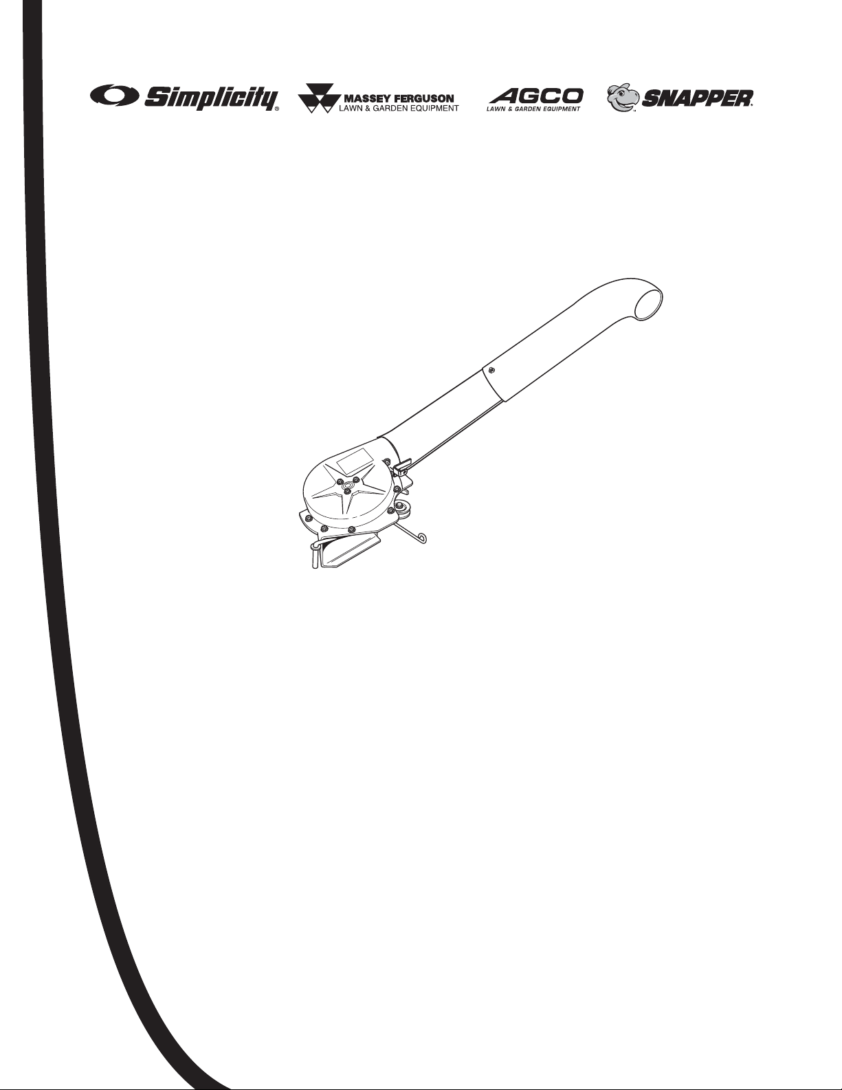
OPERATOR’S MANUAL
Turbo Vacuum System
For 38”, 44” & 50” Mower Decks
Manual No. 1732839
Revision 02
Revision Date 10/2006
TP 100-4286-02-AT-SMAN
Mfg. No. Description
1694924 Turbo Vacuum Collection System
Page 2

1
Table of Contents
Safety Rules & Information......................................2
Safety Rules ..........................................................................2
Safety Decals ........................................................................3
Safety Icons...........................................................................3
Identification Numbers...........................................................4
Assembly...................................................................5
Initial Assembly......................................................................5
Normal Removal and Installation ..........................20
Normal Removal and Installation.........................................20
NOTE: In this manual, “left” and “right” are referred to as seen from
the operating position.
Safety
Assembly
Normal Removal & Installation
Page 3

2
www.SimplicityMfg.com | www.MasseyLawn.com | www.AGCOLawn.com | www.Snapper.com
Safety
Read these safety rules and follow them closely. Failure to obey these rules could result in loss of
control of unit, severe personal injury or death to you, or bystanders, or damage to property or
equipment. This mowing deck is capable of amputating hands and feet and throwing objects. The
triangle in text signifies important cautions or warnings which must be followed.
PREPARATION
1. Do not operate the equipment without wearing
adequate outer garments and safety goggles.
Avoid loose-fitting clothes and use protective
footwear that will improve footing on slippery
surfaces.
TRAINING
1. Read the operating and service instructions
carefully. Be thoroughly familiar with the controls
and the proper use of the equipment. Know how
to stop the unit and disengage the control quickly.
2. Keep the area of operation clear of all persons,
particularly small children, and pets.
GENERAL OPERATION
1 Know the tractor controls and how to stop quickly.
READ THE TRACTOR OPERATOR’S MANUAL.
2 Read and obey all safety decals.
Only allow responsible adults, who are familiar with
the instructions, to operate the unit.
3 Disengage the electric clutch (PTO). Shut off the
engine and wait for all moving parts to stop before
attaching, adjusting, or disconnecting any part of
the collection system.
4 Check the collection system to make sure it is
bolted tightly to the tractor.
5 DO NOT operate the mower without either the
entire grass catcher or the deflector in place.
6 Turn off the PTO switch to disengage the blades
when not mowing.
7 DO NOT mow in reverse. Always look down and
behind before and while travelling in reverse.
8 DO NOT turn sharply when travelling alongside a
building or any object. Slow down before turning.
9 DO NOT carry passengers on the tractor.
10 When blower assembly is removed from the
mower deck, the deflector must be properly
installed.
11 If the mower stalls or the turbo blower chute plugs:
a. Disengage the electric clutch (PTO);
b. Stop the engine and remove the key;
c. Set the parking brake, and wait for all moving
parts to stop.
D. Remove the foreign object or clear the chute with a
piece of wood before restarting the engine.
NEVER place hands into blower housing to clear
jammed object. Blower may rotate when object is
removed.
12 For added tractor stability and to prevent tipping or
loss of control:
a. Use reduced speed on uneven ground and
when turning corners.
b. Reduce loads on hillsides. It is recommended
that the collection system be kept only half full
when negotiating any slopes. Start mowing on
slopes when the collection system is empty.
c. Mow up and down the face of slopes; never
across the face of any slope.
12. Never operate the machine without proper guards,
plates, or other safety protective devices in place.
13. Use only attachments and accessories approved
of by the manufacturer or the machine.
CHILDREN
Tragic accidents can occur if the operator is not alert to
the presence of children. Children are often attracted to
the unit and the operating activity. Never assume that
children will remain where you last saw them.
1. Keep children out of the work area and under the
watchful care of another responsible adult.
2. Be alert and turn unit off if children enter the area.
3. Never allow children to operate the unit.
SERVICE AND MAINTENANCE
1. Keep machine, attachments, and accessories in
safe working condition.
2. Clear debris from machine before each use.
3. Always refer to the operating instructions for
important details if the machine is to be stored for
an extended period.
4. The collector bag will deteriorate with time and
use. Inspect it regularly and replace if it becomes
worn.
Page 4
3
Safety
Safety Decals
This unit has been designed and manufactured to
provide you with the safety and reliability you would
expect from an industry leader in outdoor power
equipment manufacturing.
Although reading this manual and the safety
instructions it contains will provide you with the
necessary basic knowledge to operate this equipment
safely and effectively, we have placed several safety
labels on the unit to remind you of this important
information while you are operating your unit.
All DANGER, WARNING, CAUTION and
instructional messages on your unit should be
carefully read and obeyed. Personal bodily injury can
result when these instructions are not followed. The
information is for your safety and it is important! The
safety decals below are on your unit.
If any of these decals are lost or damaged, replace
them at once. See your local dealer for replacements.
These labels are easily applied and will act as a
constant visual reminder to you, and others who may
use the equipment, to follow the safety instructions
necessary for safe, effective operation.
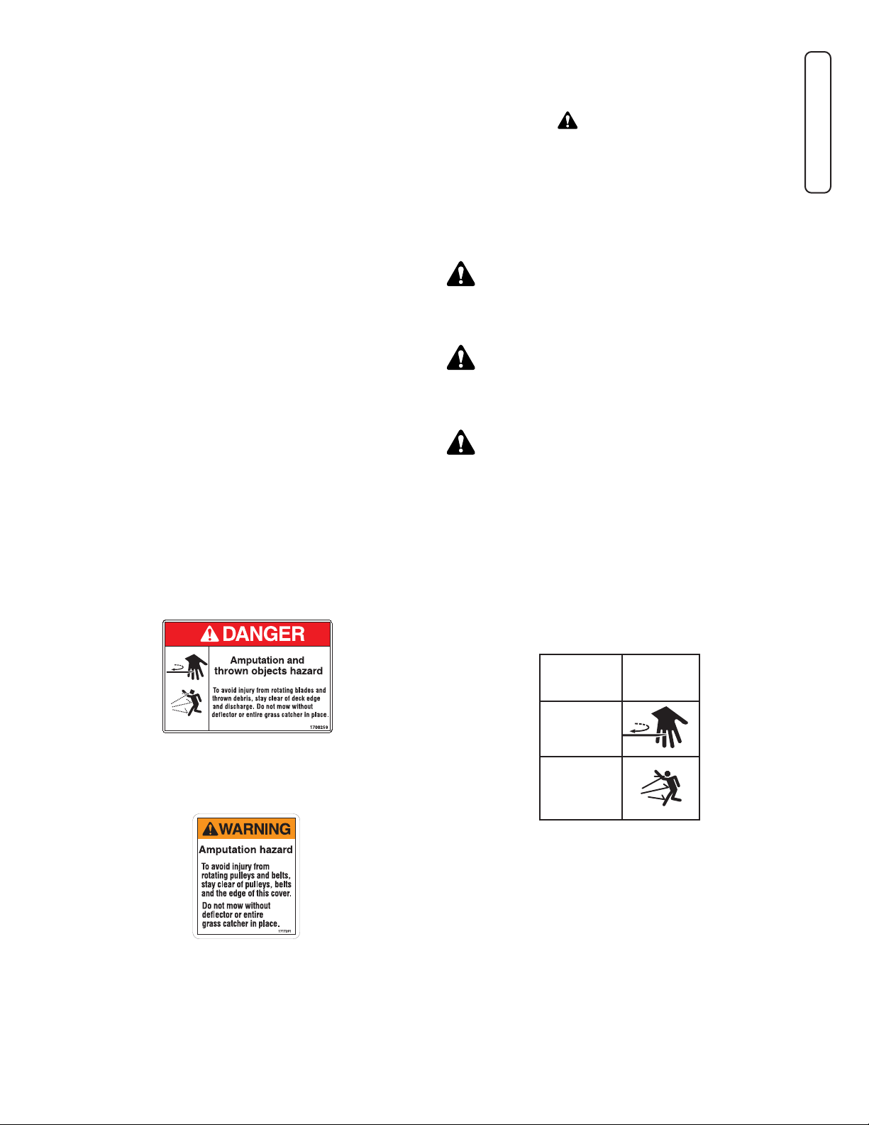
Decal - Danger, Thrown Objects /
Rotating Blades, Part No. 1700259
Decal - Warning, Shield Placement /
Deflector Position, Part No. 1717291
Safety Icons
The alert symbol is used to identity safety
information about hazards that can result in personal
injury. A signal word (DANGER, WARNING, or
CAUTION) is used with the alert symbol to indicate
the likelihood and the potential severity of the injury.
In addition, a hazard icon may be used to represent
the type of hazard. An explanation of hazard levels
and icons are as follows:
DANGER
This indicates a hazard which, if not avoided, will
result in serial injury or death.
WARNING
This indicates a hazard which, if not avoided, could
result in serial injury or death.
CAUTION
This indicates a hazard which, if not avoided, might
result in minor or moderate injury.
CAUTION or NOTICE
These messages presented without the alert symbol
indicate a situation where the unit or property could be
damaged.
Hazard Safety
Icon
Amputation
- Rotating
Parts
Thrown
Objects
DANGER
Amputation and
thrown objects hazard
To avoid injury from rotating blades and
thrown debris, stay clear of deck edge
and discharge. Do not mow without
deflector or entire grass catcher in place.
1700259
1700259
Page 5
4
www.SimplicityMfg.com | www.MasseyLawn.com | www.AGCOLawn.com | www.Snapper.com
Safety
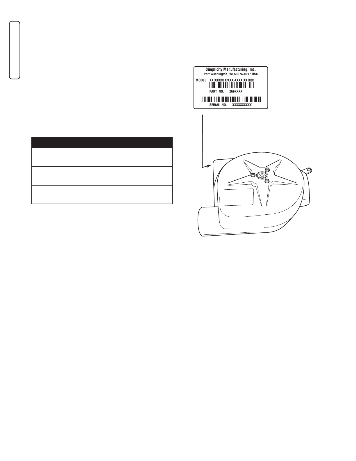
When contacting your authorized dealer for
replacement parts, service, or information on the
chassis or engine, you MUST have these
numbers.
Record your model name/number, manufacturer’s
identification numbers, and engine serial numbers in
the space provided for easy access. These numbers
can be found in the locations shown.
CE Models: Place the extra copy of the identification
tag in this manual.
SSAAMMPPLLEE
Identification Numbers
Attachment Identification Data
Model Description Name/Number
Unit PART Number Unit SERIAL Number
Dealer Name Date Purchased
Page 6
5
Assembly
4343
1
2
2
3
5
6
4
8
7
5
6
8
1010
1111
9
6
1212
2
2
1313
6
1414
1717
2
2222
2323
2424
2626
2323
2727
2828
3232
3131
5
3030
2929
3333
3434
3535
3636
3737
3838
2121
2020
1919
6
1111
4747
4949
50"50"
44"44"
1818
6767
5151
4949
44”/50”44”/50”
7
38”38”
5050
38”38”
44”/50”44”/50”
MOUNT TO MOUNT TO
STONE GUARDSTONE GUARD
ROLLER REPLACESROLLER REPLACES
ROLLER ON RIGHTROLLER ON RIGHT
END.END.
1515
1616
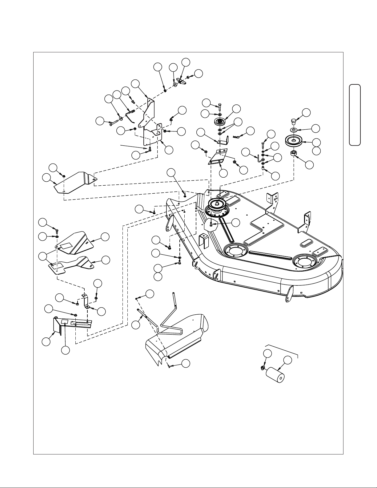
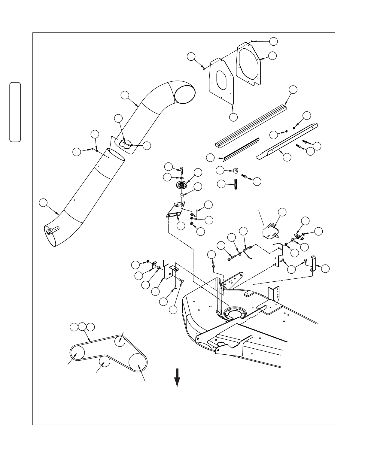
Initial Assembly
Figure 1. Package Contents
Page 7
6
www.SimplicityMfg.com | www.MasseyLawn.com | www.AGCOLawn.com | www.Snapper.com
Assembly
40
BLOWER
SPRING
LOADED
IDLER
MOWER
ARBOR
FIXED
IDLER
41
39
21
25
20
48
25
21
45
42
20
20
17
46
53
52
8
54
11
13
16
15
49
51
56
50
17
67
44
28
27
22
23
24
31
23
57
58
VIEWED FROM TOP
FRONT
62
63
64
66
65
61
60
61
59
60
38" MOWER
AT TACH TO TURBO
COVER FLANGE
Figure 1a. Package Contents (continued)
65
42
61
44
59
50
62
61
60
60
51
49
67
17
56
21
48
64
66
13
45
AT TACH TO TURBO
COVER FLANGE
15
16
25
25
20
39
VIEWED FROM TOP
40
41
57
FIXED
IDLER
17
46
53
21
52
23
22
54
27
24
58
28
63
31
23
11
BLOWER
SPRING
LOADED
IDLER
MOWER
ARBOR
FRONT
38" MOWER
Page 8

7
Assembly
Ref Part No. Qty. Description
1 1722546A 1 PIVOT & BRACKET ASSEMBLY
2 1931277 5 NUT, Hex, Flange Lock, 5/16-18
3 1718304A 1 SUPPORT, Belt Cover
4 1724376A 1 BELT Cover, 50” Mower Decks
5 1919326 4 WASHER, 5/16
6 1923325 5 CAPSCREW, 5/16-18 x 7/8
7 1931333 2 Carriage Bolt, 5/16-18 x 3/4
8 1931317 2 Carriage Bolt, 1/4-20 x 3/4
9 1717291 2 DECAL, Warning
10 1732591A 1 COVER
11 1960685 2 NUT, Hex, KEPS Lock, 1/4-20
12 1732592A 1 BAFFLE
13 1960318 1 CAPSCREW, 5/16-18 x 2-1/2
14 1732619A 1 SUPPORT
15 1705064 1 SPRING LATCH
16 1919381 1 WASHER
17 1960636 2 NUT, Hex, KEPS Lock, 5/16-18
18 1724374A 1 BELT Cover, 44” Mower Decks
19 1718295 1 ROD
20 1933896 11 NUT, Hex, #10-24
21 1960404 11 SCREW, Phillips #10-24 x 3/4
22 1923701 1 CAPSCREW, 3/8-16 x 2
23 1924940 3 WASHER, 3/8
24 1714817 1 PULLEY, Idler, 2-3/4 O.D.
25 1910531 2 WASHER
26 1724373A 1 “L” BRACKET
27 1704768A 1 “Z” BRACKET
28 1931211 1 NUT, Hex, Flange Lock, 3/8-16
29 1921221 1 CAPSCREW, 5/16-18 x 1-1/2
30 1917356 1 LOCKWASHER, 5/16
31 2172845 1 BELT STOP
32 1710703 1 SPACER
33 1733078 1 NUT, Sleeve, 9/16-18
34 1603592 1 WASHER, Bellville
35 1709941 1 PULLEY, 4-5/16 O.D.
36 1713623 1 HUB
37 1960520 1 PUSH NUT, 5/8
38 1713540 1 ROLLER
39 1719719 1 TUBE & CLIP ASSEMBLY
40 1732801 1 V-BELT, 39-5/8, 50” Mower Decks
41 1705142 1 V-BELT, 39-11/16,
44” Mower Decks
42 1732735A 1 FLANGE, Seal
43 N/A 1 DECAL, Patent
44 1733077 1 LATCH
45 1732799 1 SEAL
46 1705308A 1 “L” BRACKET
47 1960074 1 CLIP, Hair Pin
48 1732800 1 ELBOW
49 1919438 1 NUT, Hex, Nylock, 5/16-18
50 1930601 3 SCREW, Hex, Taptite,
5/16-18 x 5/8
51 720727 1 WINGNUT, 5/16
52 1733076 1 DEFLECTOR
53 1666294 1 SPACER
Ref Part No. Qty. Description
54 1960223 1 CARRIAGE BOLT, 5/16-18 x 1-1/4
55 1713091 1 PULLEY, 5.0 O.D.
56 1722750A 1 UP-STOP BRACKET
57 1724372 1 V-BELT, 47-11/16,
38” Mower Decks
58 1667811 1 SPACER
59 1733580A 1 DEFLECTOR PLATE
60 1960404 2 SCREW, #10-24 x 3/4
61 1933896 2 NUT, Nylock, #10-24
62 1733579 1 SEAL, Rubber, Thick
63 1717496 1 SEAL, Rubber, Thin
64 1719777 1 COLLAR
65 1928721 1 SCREW, Set
66 1729277 1 SPRING, Compression
67 1709256 1 WASHER, CUP
Page 9

8
www.SimplicityMfg.com | www.MasseyLawn.com | www.AGCOLawn.com | www.Snapper.com
Assembly
Figure 3. Install Discharge Baffles - 38” Mower
A. Discharge Baffle
B. Carriage Bolt, 1/4-20 x 3/4
C. Locknut, KEPS, 1/4-20
D. Carriage Bolt, 5/16-18 x 1-1/4
E. Spacer
F. Bracket
G. Locknut, KEPS, 5/16-18
H. Stone Guard
Remove Deflector and Arbor Cover - All
Models
1. Remove the mower deck from the unit (see
Operator’s Manual for Mower Deck Removal).
Remove and discard the carriage bolts, washers,
lockwashers, nuts (A, Figure 2) and deflector rod.
Retain the deflector.
2. Remove and discard the taptite screws (D) and
arbor cover (C).
Install the Discharge Baffle
38” MOWER DECKS
1. Install discharge baffle (A, Figure 3) using 1/4-20 x
3/4 carriage bolt (B) and 1/4-20 locknut (C). Do
not tighten hardware at this time.
2. Install 5/16-18 x 1-1/4 carriage bolt (D), spacer (E),
bracket (F) and 5/16-18 locknut (G) as shown.
3. Tighten all hardware.
44 AND 50” MOWER DECKS
1. Install discharge baffle (A, Figure 4) to stone guard
(G) using 5/16-18 x 7/8 capscrew (F) and 5/16-18
locknut (E) as shown.
2. Install discharge baffle assembly (A) to mower
deck over cover (B) using 1/4-20 x 3/4 carriage
bolt (D) and 1/4-20 locknut (C) as shown. Do not
tighten hardware at this time.
3. Install front of cover (B, Figure 4) to front of mower
deck using 1/4-20 x 3/4 carriage bolt (D) and 1/420 locknut (C). Do not tighten hardware at this
time.
4. Tighten all hardware.
Figure 2. Remove Deflector and Arbor Cover
A. Carriage Bolts, Washers, Lockwashers, & Nuts
B. Deflector
C. Arbor Cover, Right Hand
D. Taptite Screws
A
D
D
C
G
C
F
H
E
A
B
D
Figure 4. Install Discharge Baffles - 44” and 50”
Mower
A. Discharge Baffle Assembly
B. Cover, Mower
C. Locknut, KEPS, 1/4-20
D. Carriage Bolt, 1/4-20 x 3/4
E. Locknut, Whiz, 5/16-18
F. Capscrew, 5/16-18 x 7/8
G. Stone Guard
C
C
B
E
D
F
D
A
G
B
Page 10

9
AssemblyAssembly
Figure 5. Install Deflector Hinge and Bracket
A. Deflector Support Rod
B. Pivot Bracket
C. Carriage Bolts, 5/16-18 x 3/4
D. Capscrew, 5/16-18 x 7/8
E. Washer, Flat, 5/16
F. Nut, Whizlock, 5/16-18
G. Support, Belt Cover
Figure 6. Install Deflector
A. Deflector
B. Screws, Phillips, #10-24 x 3/4
C. Nuts, Nylock, #10-24
D. Rod, Deflector
E. 13/64” Hole Locations
Install the Deflector Hinge, Bracket and
Deflector
1. Slide the deflector support rod (A, Figure 5) into
pivot bracket (B) as shown.
2. Secure the front of the pivot bracket (B) using
5/16-18 x 3/4 carriage bolt and 5/16-18 nut (F).
3. 38” Mowers - Secure the back of pivot bracket (B)
and support (G) using 5/16-18 x 3/4 carriage bolt
and 5/16-18 nut (F).
44” and 50” Mowers - Secure the back of pivot
bracket (B) and support (G) using 5/16-18 x 7/8
capscrew, 5/16 washer (E) and 5/16-18 nut (F).
4. Drill four 13/64” holes from the bottom of the
deflector (A, Figure 6) at the pre-molded drill hole
locations (E).
5. Attach the deflector (A) to the rod (D) using the
#10-24 screws (B) and #10-24 nuts (C).
F
C
F
A
G
E
D
B
B
B
C
C
A
D
E
E
Page 11

10
www.SimplicityMfg.com | www.MasseyLawn.com | www.AGCOLawn.com | www.Snapper.com
Assembly
A
Figure 7. Discard Taptite Screws
A. Taptite Screws
Install Idler Assembly and Belt Guide
1. Remove and discard the two taptite screws (A,
Figure 7) from the locations shown.
2. Check that the idler assembly stack-up is correct
for your application See Figure 8. If not follow the
descriptions to make the corrections.
3. Install 5/16-18 x 7/8 capscrews (C, Figure 9)
through the mower deck and arbor as shown.
Tighten capscrews.
4. Install the idler assembly (A) to the mower deck
using 5/16-18 x 7/8 capscrews (C) and 5/16-18
nuts. The belt guide should be positioned as
shown.
5. 44” and 50” Mowers - Remove and discard the
taptite screw in existing hole (F, Figure 10) if unit
has roller bars.
6. 44” and 50” Mowers - Install wire belt guide (A,
Figure 10), spacer (E) washers (D), washer (C)
and capscrew (B) as shown.
Figure 9. Install Idler Assembly
A. Idler Assembly
B. Belt Guide
C. Capscrew, 5/16-18 x 7/8
D. Nut, Whizlock, 5/16-18
B
D
C
A
G
A
B
C
B
F
B
D
E
Figure 8. Idler Assembly Stack-Up
A. Capscrew, 3/8-16 x 2
B. Washer(s), 3/8
C. Pulley, Idler, 2-3/4
D. Idler Bracket
E. Nut, Whiz Lock, 3/8-16
F. Belt Guide, Wire, 38” Mowers
G. Belt Guide, Flat, 44” and 50” Mowers
H. Spacer
38” Mowers
44” and 50”
Mowers
H
Page 12

11
Assembly
Figure 11. Remove Hardware
A. Locknut
B. Spring Washers
C. Pulley
D. Spacer
C
A
D
B
Figure 12. Install Turbo Drive Pulley
A. Sleeve Nut (New)
B. Spring Washer (New)
C. Turbo Drive Pulley, 5” for 38” Mowers (New)
D. Turbo Drive Pulley, 4-5/16” for
44” & 50” Mowers (New)
E Spacer (New)
F. Pulley (Existing)
G. Spacer (Existing)
F
A
G
B
C
E
D
Torque to 55-70 ft. lbs.
(75 - 95 Nm.)
Install the Turbo Drive Pulley
1. Remove the arbor drive belt from the right side
arbor pulley.
2. Remove and discard locknut (A, Figure 11), and
spring washers (B). Retain pulley (C) and spacer
(D).
3. Install new spacer (E, Figure 12), turbo drive
pulley (C, 5” for 38” mowers or D, 4-5/16 for 44” &
50” mowers), and spring washer (B) align the
notches in the pulleys with the ridges in the
spacers. Torque the sleeve nut to 55-70 ft. lbs.
4. Install the arbor drive belt from the right side arbor
pulley.
B
A
E
D
C
F
Figure 10. Install Wire Belt Guide 44” & 50” Mower
Deck
A. Wire Belt Guide
B. Capscrew, 5/16-18 x 1-1/2
C. Lockwasher, 5/16
D. Washers, Flat, 5/16
E. Spacer
F. Existing Hole
Page 13

12
www.SimplicityMfg.com | www.MasseyLawn.com | www.AGCOLawn.com | www.Snapper.com
Assembly
F
A
C
H
B
C
D
E
G
Figure 14. Deflector Latch Stack-Up
A. Nut, Nylock 5/16-18
B. Wingnut, Special, 5/16-18
C. Washers, Flat, 5/16
D. Nut, KEPS Lock, 5/16-18
E. Spring Latch
F. Bracket, Latch, 44” and 50” Mowers
G. Bracket, Latch, 38” Mowers
H. Capscrew, 5/16-18 x 2-1/2
Bracket (F) mounts
to Baffle Bracket on
44” & 50” Mowers
Bracket (G)
mounts to
Mower Deck on
38” Mowers
Install Deflector Latch - 38”
Note: The 44” & 50” deflector latch is typically per
assembled and attached to the deflector bracket.
Check that the deflector latch stack-up is correct. See
Figure 14. If necessary revise stack-up as follows:
44” and 50” Mowers - Insert 5/16-18 x 2-1/2
capscrew (H) into bracket (F). Install 5/16 washer (C),
spring latch (E), 5/16-18 nut (D), 5/16 washer, 5/16-18
wingnut (B) and 5/16 nylock nut (A) onto capscrew (H)
as shown.
38” Mowers - Slide 5/16 washer (C), spring latch (E)
onto 5/16-18 x 2-1/2 capscrew (H). Install bracket (G)
5/16-18 nut (D), 5/16 washer, 5/16-18 wingnut (B) and
5/16 nylock nut (A) onto capscrew (H) as shown to
make deflector latch assembly.
1. Install the deflector latch assembly (A, Figure 15)
to existing holes (C) securing with 5/16-18 x 5/8
capscrews (B).
Figure 15. Install Deflector Latch Assembly - 38” Mower
A. Defector Latch Assembly
B. Capscrews, Taptite, 5/16-18 x 5/8
C. Existing Holes in Mower Deck
A
B
C
Install Up-Stop - 38” Mowers
1. Install the up-stop (A, Figure 13) securing with
5/16-18 x 5/8 capscrew (B) as shown.
Figure 13. Install Up-Stop
A. Up-Stop
B. Capscrew, Taptite, 5/16-18 x 5/8
A
B
Page 14

13
Assembly
Install Turbo Belt and Mounting Latch
1. Select the correct belt for the mower deck used.
See parts listing on page 6-7. Loosen the
hardware securing the drive pulley belt guide (B,
Figure 17 or 18) and the idler pulley (C).
2. Install the belt as shown in Figure 17 or 18.
3. Tighten the hardware securing the drive pulley belt
guide (B, Figure 17 or 18) and the idler pulley (C)
so the idler belt guide is within 1/16” (1.59mm) of
the belt.
4. Remove and retain hardware (D, Figure 17 or 18).
See Figure 16 for hole location. Install the
mounting latch (A, Figure 17 or 18) reusing
hardware (D). Latch may have to be repositioned
later.
D
D
C
Figure 17. Belt Routing - 38” Models
A. Mounting Latch
B. Drive Pulley Belt Guide Hardware
C. Idler Pulley
D. Hardware
B
A
D
D
C
Figure 18. Belt Routing - 44” and 50” Models
A. Mounting Bracket
B. Drive Pulley Belt Guide Hardware
C. Idler Pulley
D. Hardware
B
A
Figure 16. Mounting Latch Holes
38” Mounting Hole Location
44” & 50”
Mounting Hole
Location
Page 15

14
www.SimplicityMfg.com | www.MasseyLawn.com | www.AGCOLawn.com | www.Snapper.com
Assembly
Figure 20. Turbo Belt Routing
A. Turbo Drive Belt
B. Mower Deck Drive Pulley
C. Belt Tension Lever
D. Idler Pulleys
E. Mower Deck Turbo Drive Pulley
F. Turbo Drive Pulley
Figure 21. Remove Right Side Pushnut and Roller
A. Roller, Hollow
B. Pushnut, 5/8
B
E
C
F
D
A
B
A
Figure 22. Install Right Side Pushnut and Roller
A. Roller, Solid
B. Pushnut, 5/8
B
A
Install Turbo, Belt and Roller
1. Place the mower deck in the highest cut position.
2. Slide the pivot pin (A, Figure 19) into pivot bracket
(F).
3. Raise the deflector (B).
4. Rotate the turbo (C) and “latch” the slot in the
turbo housing over and onto the anchor bracket
(D). Slot in mounting latch (A, gure 17 & 18) to be
around outside nut. If not - reposition mounting
latch on turbo. Tighten the wingnut (E) and
cupwasher to secure turbo (C).
5. Attach the mower drive pulley to the mower deck
drive pulley (B, Figure 20).
6. Pull back (away from deck) on belt tension lever
(C).
7. Install the turbo drive belt on pulleys as shown and
release the belt tension lever (C).
8. Models With Rollers - Remove and discard the
pushnut (B, Figure 21) and roller (A) from the right
side of mower deck as shown.
9. Models With Rollers - Install the roller (A, Figure
22) and 5/8 pushnut (B) from the right side of
mower deck as shown.
Figure 19. Install Turbo Blower
A. Pivot Pin
B. Deflector
C. Turbo
D. Anchor Bracket
E. Wingnut
F. Pivot Bracket
D
C
E
B
A
F
Page 16

15
Assembly
10. 44 and 50” Models - Attach the belt cover (B,
Figure 23) to support bracket (E) securing with
5/16-18 x 1 capscrew (C), washer (D) and 5/16-18
nut.
Figure 23. Install Belt Cover Plate
A. Belt Latch
B. Belt Cover
C. 5/16-18 x 1 Capscrew
D. 5/16 Washer
E. Support Bracket
F. 5/16-18, Nut, Nylock
50" Only
B
E
C
F
A
D
A
B
C
C
C
Figure 24. Drill Adapter Plate Holes
A. Cover Plate
B. Grass Catcher Cover
C. New13/64” Hole Locations
Install Seal, Cover, tubes and Turbo
1. Use cover plate (A, Figure 23) as a template to
drill six 13/64” holes (C) on grass catcher cover (B)
as shown.
2. Inside grass catcher cover (B, Figure 25) place
seal (D), and cover plate (A). Secure using #1024 x 3/4 screws (C), and #10-24 locknuts (D).
A
B
E
C
Figure 25. Install Seal and Cover Plate
A. Cover Plate
B. Grass Catcher Cover
C. Screw, Phillips, #10-24 x 3/4
D. Seal, Rubber
E. Locknuts, ESNA, #10-24
B
E
C
C
D
CAUTION
Before you begin operating the unit with the
Turbo attached, be certain you have read all of
the safety information in this Operator’s
Manual, as well as the Operator’s Manual for
the tractor and any grass catchers or other
collection devices used in conjunction with
this turbo blower.
44" Only
Belt Cover
Page 17

16
www.SimplicityMfg.com | www.MasseyLawn.com | www.AGCOLawn.com | www.Snapper.com
Assembly
E
A
C
Figure 26. Install Tubes
A. Lower Tube
B. Upper Tube
C. Screw, Phillips, #10-24 x 3/4
D. Washer, Flat
E. Locknut, ESNA, #10-24
D
B
A
C
B
Figure 27. Connect Tube to Hood and Turbo
A. Seal
B. Discharge end of Tube Assembly
C. Clip
D. Nut and Capscrew
E. Intake end of Tube Assembly
D
3. Slide upper tube (B, Figure 26) over lower tube (A)
secure with #10-24 x 3/4 screw (C), washers (D)
and #10-24 locknut (E).
Note: The grass catcher hitch, channel and cover
must be installed according to the Catcher Operator’s
Manual before proceeding with the next steps.
4. Slide the discharge end of tube assembly (A,
Figure 27) through the seal (A). This may require
some rotating or turning of the discharge end of
tube assembly.
5. Slide the intake end of tube assembly (E) over the
turbo aligning clip (C) and nut and capscrew (D).
6. Lift clip (C) over nut and capscrew to secure tube
to turbo.
E
Page 18

17
Assembly
Figure 28. Install Deflector Plate
A. Deflector Plate
B. Cover
C. New 7/32” Holes
D. Screws, #10-24 x 3/4
E. Locknuts, #10-24
A
D
A
C
C
E
E
D
B
C
A
Figure 29. Install Thick Seal
A. Thick Seal
B. Corner, LH
C. Hinge Edge
B
Triple Collector - Plate and Edging
1. Hold deflector plate (A, Figure 28) in cover (B) as
shown and mark new hole locations using
deflector plate holes as a guide.
2. Drill two 7/32” holes in the locations marked in the
previous step.
3. Secure deflector plate (A) to cover (B) using #1024 x 3/4 screws (D) and #10-24 locknuts (E).
4. From the inside of grass catcher slide the thick
seal (A, Figure 29) starting at the LH side of the
hinge edge (C) to the corner (B) on the cover edge
as shown.
Twin Collectors - Edging
1. From the inside of grass catcher slide the thin seal
(A, Figure 30) onto the cover edge (B) starting at
the LH side of the hinge edge (D) so that the
inside curl (C) is toward the inside of the cover .
2. From the inside of grass catcher slide the thick
seal (A, Figure 5) on the cover edge as shown
starting at the out side end of the thin seal (B) and
continuing around the cover.
Figure 30. Install Thin Edging
A. Thin Edging
B. Cover Edge, LH
C. Inside Curl
D. Hinge Edge
A
B
D
C
Page 19

18
www.SimplicityMfg.com | www.MasseyLawn.com | www.AGCOLawn.com | www.Snapper.com
Assembly
Snapper Models
1. Place several blocks of wood under the mower
deck so that there is slack in the mower lift when
the mower is in the lowest position.
2. Remove the hair pin (F, Figure 33) from lift rod (A).
3. Remove the lift rod (A, Figure 32 & 33) from lift bar
(C).
4. Remove the locknut (B, Figure 33), spacer (E).
5. Mark the location of the special nut (D) on lift rod
(A) and remove nut.
Figure 32. Remove Lift Rod
A. Lift Rod
B. Lock Nut
C. Lift Bar
D. Special Nut
B
A
D
Figure 33. Remove Lift Rod
A. Lift Rod
B. Locknut
C. Lift Bar
D. Special Nut
E. Spacer
F. Hair Pin
F
C
A
D
E
B
C
C
A
Figure 31. Install Thick Seal
A. Thick Seal
B. Edge of Thin Seal
B
Page 20

19
Assembly
Figure 35. Install Lift Rod
A. Lift Rod
B. Locknut
C. Lift Bar
D. Special Nut
E. Spacer
F. Hair Pin
G. Spring
H. Lift
F
C
A
D
E
B
Figure 34. Install Set Collar
A. Lift Rod
B. Set Collar
C. Set Screw
D. Rod Tip
6. Slide set collar (B, Figure 34) onto lift rod (A).
Secure set collar (B) so that the top of the collar is
4” from the bottom of the rod tip (D) and that the
rod tip and set screw point in opposite directions.
7. Install the spring (G, Figure 35) and special nut (D)
in the same location that was marked in step 5.
8. Install the spacer (E) and locknut (B).
9. Connect special nut (D) to lift bar (C).
10. Reinstall the rod (A) to lift (H) and secure with hair
pin (F).
11. Re-level mower deck following procedures in the
Operator’s Manual see MOWER DECK
LEVELING.
C
A
D
B
A
B
D
C
H
4”
G
Page 21

20
www.SimplicityMfg.com | www.MasseyLawn.com | www.AGCOLawn.com | www.Snapper.com
Normal Remocal & Installation
Normal Removal & Installation
Figure 36. Install Turbo Blower
A. Pivot Pin
B. Deflector
C. Turbo
D. Anchor Bracket
E. Wingnut
F. Pivot Bracket
Figure 37. Turbo Belt Routing
A. Turbo Drive Belt
B. Mower Deck Drive Pulley
C. Belt Tension Lever
D. Idler Pulleys
E. Mower Deck Turbo Drive Pulley
F. Turbo Drive Pulley
D
C
E
B
Turbo & Tube Installation
Note: The grass catcher hitch, channel and cover
must be installed according to the Catcher Operator’s
Manual before proceeding with the next steps.
1. Place the mower deck in the highest cut position.
2. Slide the pivot pin (A, Figure 36) into pivot bracket
(F).
3. Raise the deflector (B).
4. Rotate the turbo (C) and “latch” the slot in the
turbo housing over and onto the anchor bracket
(D). Tighten the wingnut (E) to secure turbo (C).
5. Pull back (away from deck) on belt tension lever
(C, Figure 37).
6. Install the turbo drive belt on pulleys as shown and
release the belt tension lever (C).
7. Follow the Bagger Operator’s Manual for
installation of catcher components.
8. Slide the discharge end of tube assembly (A,
Figure 30) through the seal (A). This may require
some rotating or turning of the discharge end of
tube assembly.
9. Slide the intake end of tube assembly (E) over the
turbo aligning clip (C) and nut and capscrew (D).
10. Lift clip (C) over nut and capscrew (D) to secure
tube to turbo.
A
F
B
E
C
F
D
A
CAUTION
Before you begin operating the unit with the
Turbo attached, be certain you have read all of
the safety information in this Operator’s
Manual, as well as the Operator’s Manual for
the tractor and any grass catchers or other
collection devices used in conjunction with
this turbo blower.
Page 22

21
Normal Remocal & Installation
A
C
B
Figure 38. Connect Tube to Hood and Turbo
A. Seal
B. Discharge end of Tube Assembly
C. Clip
D. Nut and Capscrew
E. Intake end of Tube Assembly
D
E
Turbo & Tube Removal
1. Place the mower deck in the highest cut position.
2. Lift clip (C,Figure 38) over nut and capscrew and
disconnect turbo from intake end of tube
assembly.
3. Slide the intake end of tube assembly (E) out of
seal (A) and remove tube assembly.
4. Place the mower deck in the highest cut position.
5. Pull belt tension lever (C, Figure 37) away from the
discharge opening to remove tension from the belt.
Remove turbo drive belt.
6. Loosen wing nut (E, Figure 38) and lift deflector
(B). Rotate turbo (C) away from mower deck an
remove.
7. Follow the Bagger Operator’s Manual for removal
of catcher components.
WARNING
OPERATION WITHOUT TURBO, TUBE AND
BAGGER
For operation without turbo, tube and bagger,
the mower deflector MUST be properly
installed in the down position and retained by
the spring latch.
Page 23

Copyright © 2006 Simplicity Mfg. Inc.,
Port Washington, WI, USA. All rights reserved.
The Simplicity logo is a registered trademark of
Simplicity Mfg. Inc., Port Washington, WI, USA.
Contact Information:
Simplicity Mfg. Inc.
P.O. Box 997
500 N. Spring St.
Port Washington, WI 53074-0997
www.SimplicityMfg.com
Page 24

MANUFACTURING, INC.
500 N Spring Street / PO Box 997
Port Washington, WI 53074-0997
www.SimplicityMfg.com
500 N Spring Street / PO Box 997
Port Washington, WI 53074-0997
www.MasseyLawn.com
500 N Spring Street / PO Box 997
Port Washington, WI 53074-0997
AGCOLawn.com
Simplicity Mfg. Inc. - Snapper Products
535 Macon Street
McDonough, GA 30253
www.Snapper.com
 Loading...